
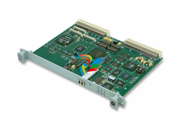
Moog G122-829A001 P-I Servoamplifier: Technical Summary
Moog G122-829A001 P-I 伺服放大器:技术摘要
介绍和范围
本文档总结了 Moog G122-829A001 的技术细节,这是一款通用的、用户可配置的 P-I(比例积分)伺服放大器。它专为各种闭环控制应用而设计,可通过内部开关和外部电位计灵活地进行调整。本摘要基于 G122-829A001 应用说明。
核心功能
G122-829A001 是一款单通道伺服放大器,可配置为在多种控制模式下运行:
Proportional (P) control: The output is proportional to the error signal.
Integral (I) control: The output integrates the error signal over time to eliminate steady-state error.
Proportional + Integral (P-I) control: Combines both P and I actions for robust control.
The selection between these modes and other operational characteristics is managed by internal DIP switches and adjustable potentiometers, making it a versatile solution for many different systems.
Physical & Installation Specifications
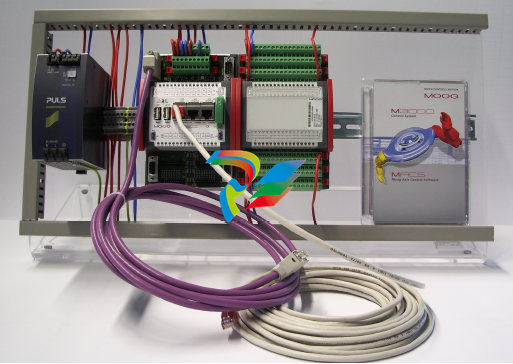
Mounting: Designed for horizontal mounting on a standard DIN rail within a suitable industrial steel enclosure.
Cooling: The case features top and bottom vents for passive cooling via airflow. These vents must be kept clear.
Wiring: Screw terminals accommodate wire sizes from 0.2mm² to 2.5mm² (24AWG to 12AWG). The use of shielded cables is recommended for all connections to ensure EMC compliance.
Power Supply: Requires a nominal 24V DC supply (range: 22V to 28V).
Inputs Configuration
The amplifier features multiple inputs that are summed at the error amplifier stage.
Feedback Input: This is the primary input for the feedback transducer signal. It is a differential input, configurable for either 4-20mA or ±10V signals. It includes front-panel-accessible potentiometers for gain and zero adjustments, making it ideal for scaling various feedback signals.
Input 1: A non-inverting ±10V input with a scale potentiometer (adjustable from 10% to 100%) and a switch-selectable 55ms input lag. It is well-suited for use as the primary command signal.
Input 2: A differential input that is switch-selectable between 4-20mA and ±10V. It can be used for either command or feedback signals.
Input 3: A direct input to the output summing amplifier, typically used for command feed-forward or for closing an outer loop in a multi-stage valve system.
Output Configuration
The amplifier's output is highly configurable to drive a wide range of proportional valves.
Valve Drive Output: Switch-selectable output type:
Voltage: ±10V into a minimum load of 200 Ohm.
Current: Selectable from ±5mA up to ±100mA, configured via a set of summing DIP switches.
4-20mA: A specific current output mode for standard industrial actuators.
Dither: A fixed 200 Hz dither signal can be enabled. Its amplitude is adjustable via a front-panel potentiometer up to ±10% of the selected valve drive.
"In Position" Signal: Provides an opto-isolated current path when the valve drive signal falls below a ±10% threshold, useful for signaling a PLC to proceed with the next step in a sequence.
Adjustments and Setup
Onboard Switches (SW1-SW7): Internal DIP switches are used to configure key operational parameters such as output type (voltage/current), integrator input source (from error amp or P-stage), I-limit, dither enable, and feedback configuration.
Front Panel Potentiometers: Multi-turn potentiometers provide fine adjustment for:
Proportional Gain (P gain)
Integral Gain (I gain)
Input 1 Scale
Error Amp Bias
Dither Level
Step Push Button (SW3): A built-in diagnostic tool that injects a -50% step disturbance into the valve drive signal. This is used for system identification and for tuning the P and I gains to achieve optimal closed-loop performance.
Enable Input: A 24V DC enable input energizes an internal relay that connects the output stage to the terminals and un-clamps the integrator. This can be permanently enabled via an internal switch for continuous operation.
-
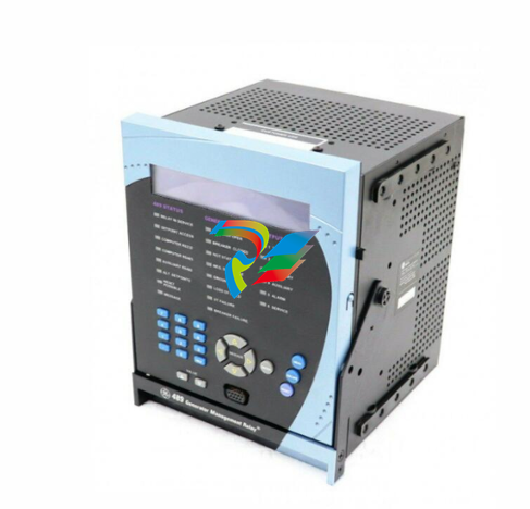
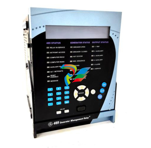
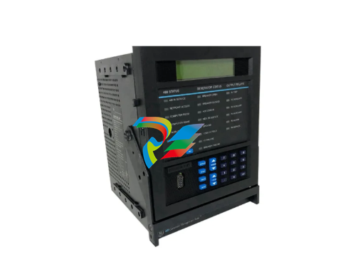 489-P1-HI-A20-E GE generator management relay
 -
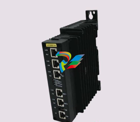 IS420UCSBS1A IS430SNUAH1A Mark VIeS Safety Controller
 -
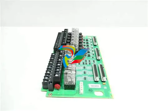
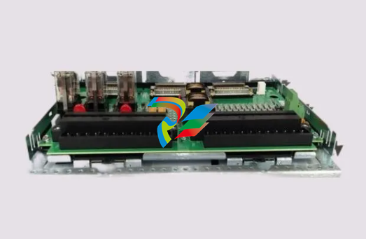 IS400JPDHG1ABB IS410JPDHG1A Power distribution board
 -
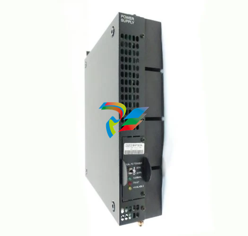 IS2020RKPSG3A VME Rack Power Supply Module
 -
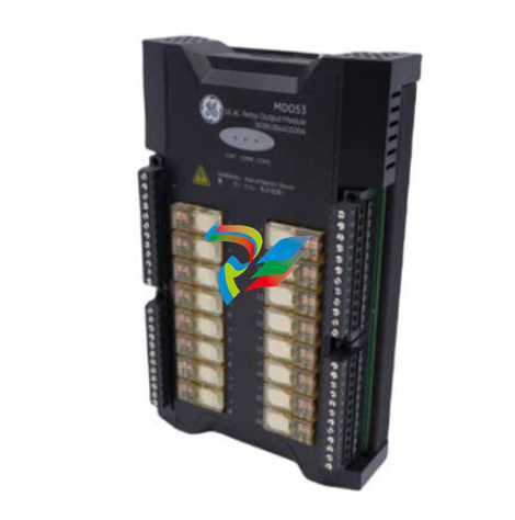
 IS410SRLYS2A IS400SRLYS2ABB Relay contact output terminal board
 -
 IS410STAIS2A IS400STAIS2AED Single-channel analog I/O terminal board
 -
 IS410STCIS2A IS400STCIS2AFF Industrial Control Module
 -
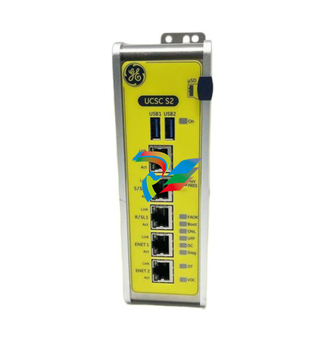 IS420UCSCS2A-B-V0.1-A Controller Module
 -
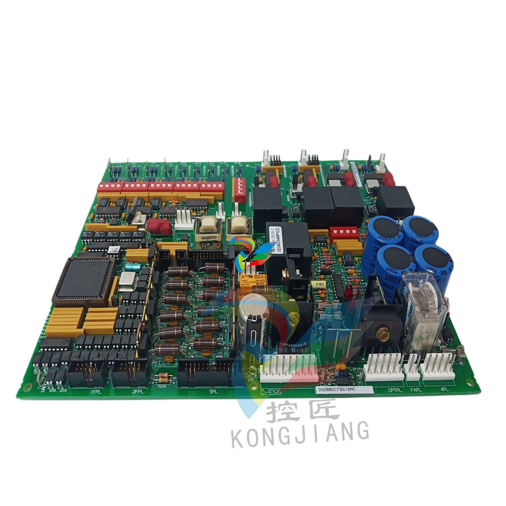
 DS200DCFBG2BNC DS200DCFBG1BNC Power supply board
 -
 IS200VPROH2B IS200VPROH1BEF IS200VPWRH1AHD
 -
 VMIC VMIVME-5565-110000 Reflective Memory Node Card
 -
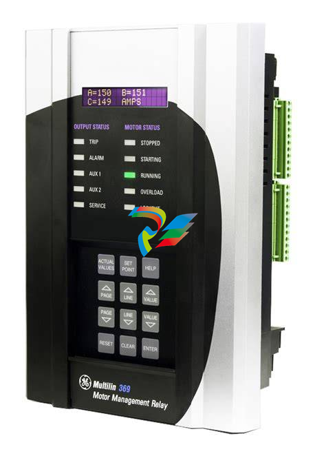 369-HI-0-M-0-E-0-E By GE Multilin Motor Management Relay
 -
 VMIVME-017807-414001 350-0001007807-414001 D
 -
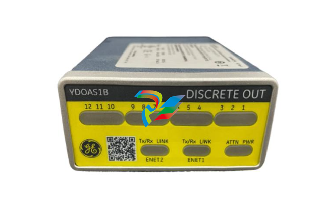 IS420YDOAS1B Discrete Output I/O Pack
 -
 Multi-channel relay SR489-P5-LO-A20-E
 -
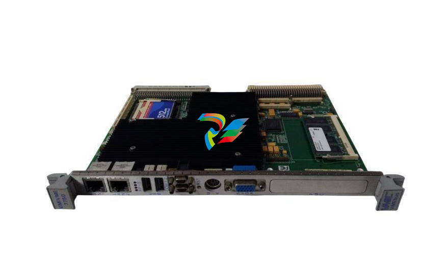 GE HR911103A VMIVME-7750 High-Performance VME Bus Processor
 -
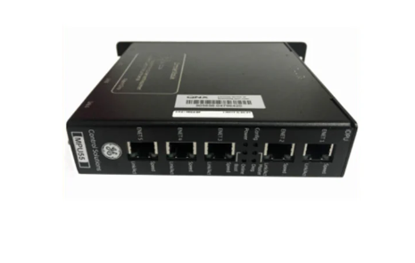
 MIFIIPI55E10HI00 High-Density Ethernet Multifunction Interface Module
 -
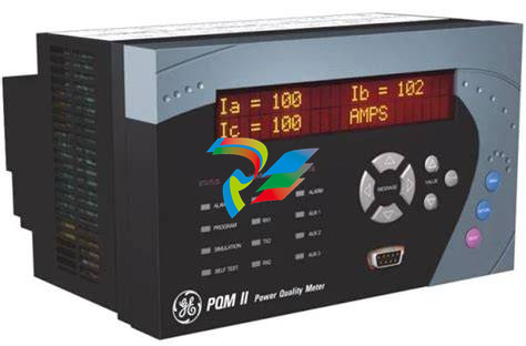 PQMII-T20-C-A PQMII Power Quality Meter
 -
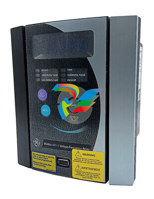 GE MIVII 1000E00HI00 High-Speed Counter Module for Precision Control
 -
 Communication control module 369B1860G0031
 -
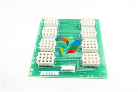
 369B1859G0021 PCB assembly
 -
 369B1844G5004 High-Performance Industrial Control Module
 -
 208D9845P0008 DC stabilized power supply module
 -
 GE 369B1860G0030 Intelligent DPU Controller Module
 -
 PACSystems™ IC695CPE400 RX3i 64 MB Rackless CPU with Field Agent Quick Start
 -
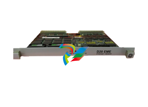
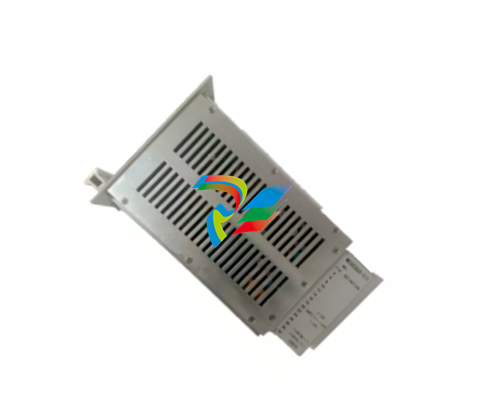
 D20EME10BASE-T 820-0474 Ethernet Communication Expansion Module
 -
 IC800SSI228RD2-CE Servo controller
 -
 Jump-type DC power distribution card IS200JPDMG1ACC S1AT005
 -
 Turbine control system module IS200TSVCH1AED
 -
 IS200TTURH1CCC terminal turbine plate
 -
 IS200TSVCH1ADC S1CX01H Servo valve interface terminal board
 -
 IS200TRPGH1BDD S1C5029 Terminal Relay Panel Module
 -
 Secure analog I/O package IS220YAICS1AL
 -
 IS420PPNGH1A GE Controller Gateway Module
 -
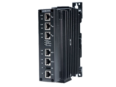
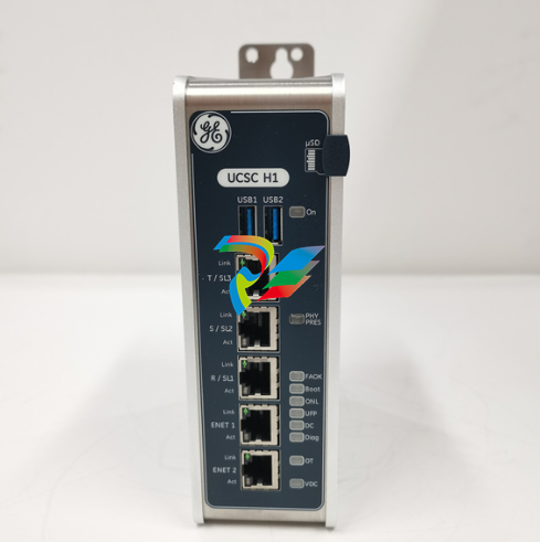 UCSC compact quad-core controller IUCSC H1 IS420UCSCH1A-B
 -
 The IC698CPE010 is a Central Processing Unit from the GE Fanuc RX7i series
 -
 IC697VDD100 Digital Output Module
 -
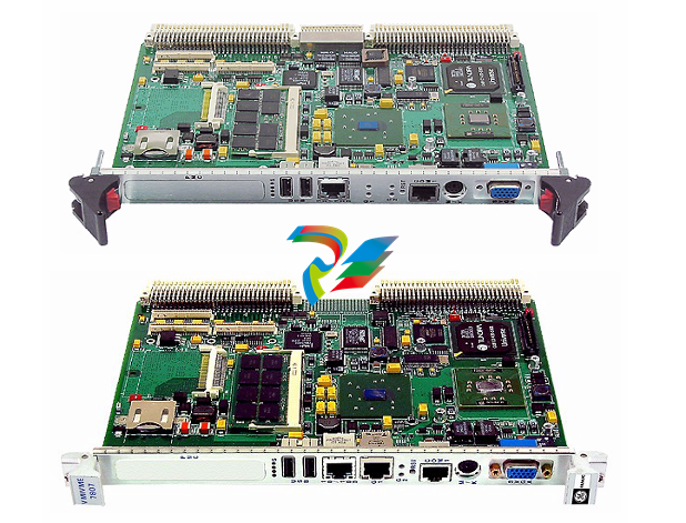
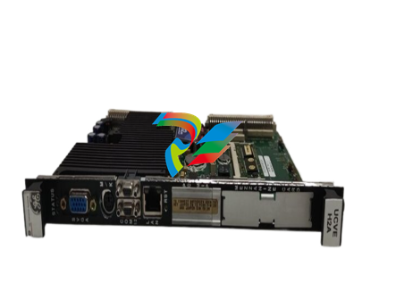
 V7768-320000 3509301007768-320000A0 6U single-board computer
 -
 TB43225-AF14 3 Pole Circuit Breaker
 -
 Induction terminal board IS410TRLYS1B
 -
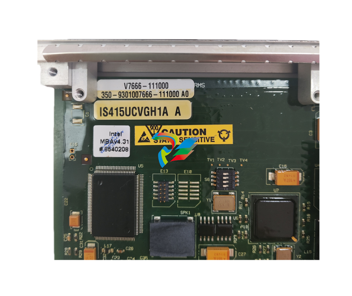 IS415UCVGH1A V7666-111000 Redundant I/O or control module
 -
 Servo motor controller IC800SSI216RD2
 -
IS210MACCH1AKH IS200WEMDH1ABA Interface Board
-
 VMIVME-5565-010000 332-015565-010000 P Reflective Memory (RFM) Node Card
 -
 IS220PDOAH1B Contact Output Module
 -
IC698CHS009 Rx7i PACsystem I/O Rack Module
-
 IS420PUAAH1A Universal input/output module
 -
 Flame detector RS-FS-9001 362A1052P004
 -
 Hydran 201Ti Mark IV Essential DGA monitoring for transformers
 -
 IS210BPPBH2BMD Redundant Power Supply Module for Mark VIe Turbine Control
 -
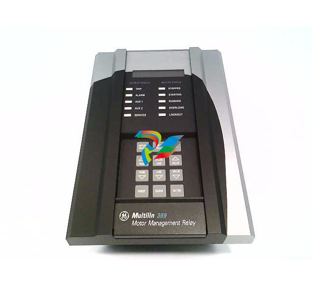
 369-HI-0-M-0-0-0-E 369 Motor Management Relay
 -
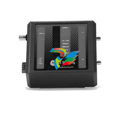 S739DVT Digital Valve Trip Module
 -
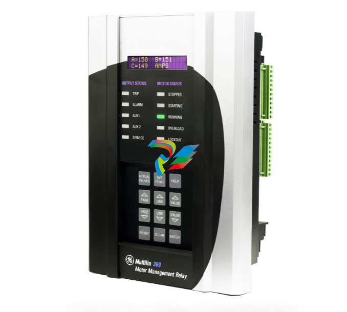
 369-HI-R-M-F-E-H-E Motor Management Relay
 -
 489-P5-HI-A20-E Multilin Relays
 -
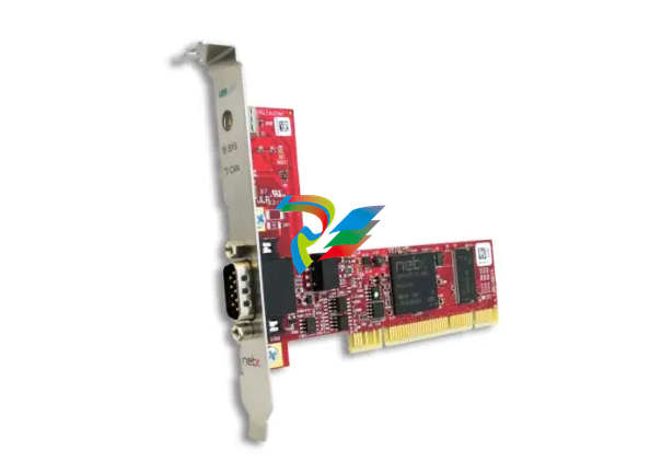 PC Card CIFX 50-CO – PCI
 -
 PC000087524/01 Power module
 -
 SR469-P5-H-A20-T Multi-Function Motor Protection Relay
 -
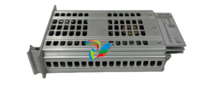 WES5120 2340-21005 On site controller main station unit
 -
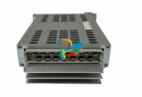 WES5120 2340-21003 Analog output module
 -
 Alstom IRVI20 - REGULATION INTERFACE BOARD
 -
 ABB DRIVEMONITOR VERSION 4000 DRIVE MODULE RBOX316-ABB-00
 -
D20MIC10BASE-T 820-0756 Network card
-
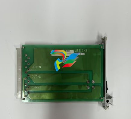
 WES13-3 5167-0001-0210 CPU/Auxiliary Control board
 -
 WES13-3 2508-21001 Embedded digital module
 -
D20ME 526-2005-216943 control module
-
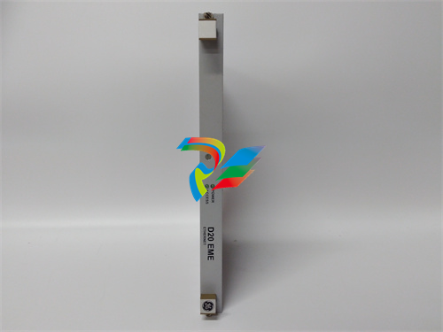
 D20EME 0526-21170-1 Enhanced Master Communications Module for D20 Substation RTUs
 -
.jpg) 2400-21004 / 2010-3101-0442 – Redundant Power Supply Module for Mark VIe Turbine Control
2400-21004 / 2010-3101-0442 – Redundant Power Supply Module for Mark VIe Turbine Control -
 PACSystems™ IC695CPE400 RX3i 64 MB
 -
 DS200DCFBG2BNC DC2000 DC Feedback Board
 -
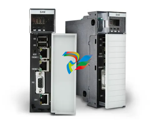 OLDI Ethernet interface module 56SAM-844
 -
IS200BPPBH2CAA Mark VIe Power Supply Module
-
 IS210MACCH2AEG Motor Control and Communication Module
 -
 IS210MACCH2AGG Mark VIe Speedtronic Turbine Control Module
 -
 IS200AEPAH1AFD Printed circuit board
 -
IS200AEPAH1ACB Analog I/O Module
-
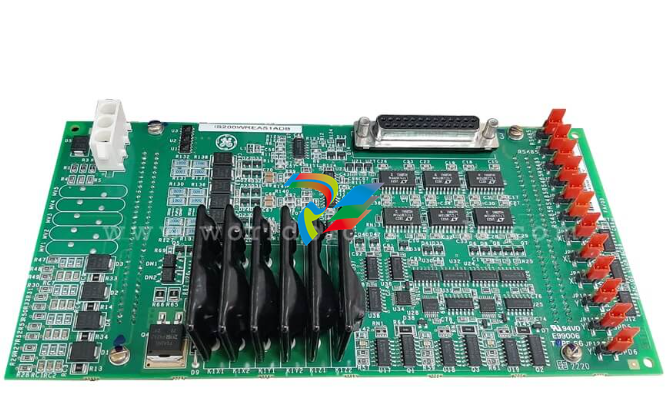 IS200WREAS1ADB AERO TRIP TB DBRD sub-board
 -
 IS200WETAH1AEC large board component made Mark VI system
 -
 IS200AEPAH1AHD A High-Precision Excitation Control Board for Turbine Systems
 -
IS200WEMAH1AEA Control board
-
IS210MACCH1AGG processor card
-
IS230TNRLH1B Discrete Output Modular Assembly
-
 Mark V Series DS200PCCAG1ACB PCB Power Connect Card
 -
 DS200SI0CG1AEA Instantaneous overcurrent card
 -
 DS200SHVMG1AGE Analog I/O board
 -
 DS200SI0CG1A6A Input/Output Module
 -
 DS200SHVMG1AFE SCR High Voltage Interface Board
 -
 DS200RT8AG3AHC Relay Output Terminal Board
 -
 DS200FSAAG1ABA PCB Field Supply Gate Amplifier Board
 -
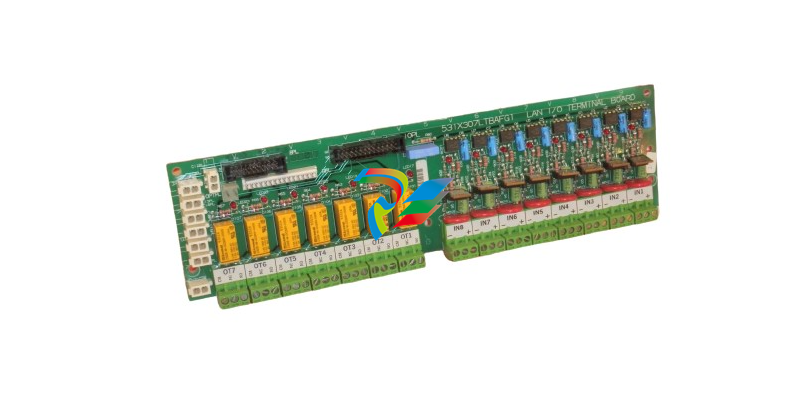 531X307LTBAFG1 F31X307LTBA LAN I/O Terminal Board
 -
ABB AFS670 19" Ruggedized Switch AFS670-EREEDDDSSEEEEEEEPZYX05.1.0
-
 NI Controller for VXI VXIPC-871B
 -
 IS200EPMCH1GE Mark VIe Patch Cord Power Distribution Card
 -
 VMICPCI-7632-03310 IS215UCCAH3A 350-657362-003310J GE gas turbine system control processor board
 -
 WEA13-13 2508-21001 Control Module / I/O Board
 -
WES5120 2340-21004 Controller Main Module
-
 WES5120 2340-21006 Field Controller Master Unit Module
 -
WESDAC D20ME 18-MAR-13 Excitation Control Module
-
 D20 EME 2400-21004 Ethernet communication and expansion module
 -
 GE DS3800XTFP1E1C Thyristor Fan Out Board Brand
 -
 GE SR745-W2-P1-G1-HI-A-L-R-E Feeder protection relay
 -
 GE IS230TNDSH2A Discrete Output Relay Module Brand
 -
GE Fanuc IS200TDBSH2ACC Mark VI Terminal Board Brand
-
 GE PMC-0247RC-282000 350-93750247-282000F Disk Drive
 -
GE PMC-0247RC-282000 350-93750247-282000F Disk Drive
-
 GE VMIVME-1150 Serial Communications Controller
 -
 GE VMIVME-5576 Fiber-Optic Reflective Memory with Interrupts
 -
GE VMIC Isolated Digital Output VMIVME-2170A
-
 GE MULTILIN 760 FEEDER MANAGEMENT RELAY 760-P5-G5-S5-HI-A20-R-E
 -
GE IS200AEPAH1BKE IS215WEPAH2BB Printed circuit board
-
 GE IS210BPPCH1A Mark VIe I/O Pack Processor Card
 -
 GE IS220PRTDH1A 336A4940CSP6 High-Performance RTD Input Module
 -
GE IS220PDIAH1BE 336A5026ADP4 Discrete Input Module
-
 GE IS420ESWBH3A IONET Switch Module
 -
 GE 516TX 336A4940DNP516TX 16-port Ethernet switch
 -
 GE EVMECNTM13 Embedded control module
 -
GE EVPBDP0001 EVPBDP032 control module
-
 GE Hydran M2-X Enhanced Monitoring with Extended Sensor Life
 -
 GE UR6CH Digital I/O Module
 -
 GE IC695CPU315-CD Central processing unit
 -
 GE 531X305NTBAMG1 DR Terminal Board
 -
 GE 531X305NTBALG1 NTB/3TB Terminal Board 531X Series
 -
 GE 531X305NTBAJG1 NTB/3TB Terminal Board.
 -
GE 531X305NTBAHG1 NTB/3TB Terminal Board 531X
-
 GE 531X305NTBAEG1 is a PCB that functions as a DR terminal board.
 -
General Electric 531X305NTBACG1 NTB/3TB Terminal Board 531X
-
 GE Digital Energy D20 Analog Input Module
 -
 GE 94-164136-001 main board Control board
 -
 GE 269 PLUS-D/O-100P-125V Digital motor relay


