
GEGenerator Protection System Generator Protection, Control and Asset Management
Overview
The relay features generator unbalance, generator differential, over excitation, loss of
excitation, 3rd harmonic neutral undervoltage, over and under frequency, synchrocheck
and other essential functions with a basic order option. Additionally available with an
advanced order option are overall differential (to protect the transformer-generator
combined), directional overcurrent elements, restricted ground fault, 100% stator ground,
out-of-step protection, rate of change of frequency, power factor, harmonic detection,
frequency out-of-band accumulation and others. An optional RTD module allows for
thermal protection and monitoring. An optional analog inputs/outputs module allows for
monitoring of generator excitation current, vibration and other parameters.
These relays contain many innovative features. To meet diverse utility standards and
industry requirements, these features have the flexibility to be programmed to meet
specific user needs. This flexibility will naturally make a piece of equipment difficult to
learn. To aid new users in getting basic protection operating quickly, setpoints are set to
typical default values and advanced features are disabled. These settings can be
reprogrammed at any time.
Programming can be accomplished with the front panel keys and display. Due to the
numerous settings, this manual method can be somewhat laborious. To simplify
programming and provide a more intuitive interface, setpoints can be entered with a PC
running the EnerVista 8 Setup software provided with the relay. Even with minimal
computer knowledge, this menu-driven software provides easy access to all front panel
functions. Actual values and setpoints can be displayed, altered, stored, and printed. If
settings are stored in a setpoint file, they can be downloaded at any time to the front panel
program port of the relay via a computer cable connected to the USB port of any personal
computer.
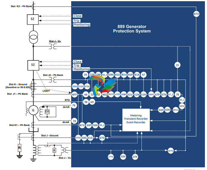
A summary of the available functions and a single-line diagram of protection and control
features is shown below. For a complete understanding of each feature operation, refer to
the About Setpoints chapter, and to the detailed feature descriptions in the chapters that
follow. The logic diagrams include a reference to every setpoint related to a feature and
show all logic signals passed between individual features. Information related to the
selection of settings for each setpoint is also provided.
Description of the 889 Generator Protection System
CPU
Relay functions are controlled by two processors: a Freescale MPC5125 32-bit
microprocessor that measures all analog signals and digital inputs and controls all output
relays, and a Freescale MPC8358 32-bit microprocessor that controls all the advanced
Ethernet communication protocols.
Analog Input and Waveform Capture
Magnetic transformers are used to scale-down the incoming analog signals from the
source instrument transformers. The analog signals are then passed through a 11.5 kHz
low pass analog anti-aliasing filter. All signals are then simultaneously captured by sample
and hold buffers to ensure there are no phase shifts. The signals are converted to digital
values by a 16-bit A/D converter before finally being passed on to the CPU for analysis.
The 'raw' samples are scaled in software, then placed into the waveform capture buffer,
thus emulating a digital fault recorder. The waveforms can be retrieved from the relay via
the EnerVista 8 Series Setup software for display and diagnostics.
Frequency
Frequency measurement is accomplished by measuring the time between zero crossings
of the composite signal of three-phase bus voltages, line voltage or three-phase currents.
The signals are passed through a low pass filter to prevent false zero crossings. Frequency
tracking utilizes the measured frequency to set the sampling rate for current and voltage
which results in better accuracy for the Discrete Fourier Transform (DFT) algorithm for offnominal frequencies.
The main frequency tracking source uses three-phase bus voltages. The frequency
tracking is switched automatically by an algorithm to the alternative reference source, i.e.,
three-phase currents signal if the frequency detected from the three-phase voltage inputs
is declared invalid. The switching will not be performed if the frequency from the
alternative reference signal is detected invalid. Upon detecting valid frequency on the
main source, the tracking will be switched back to the main source. If a stable frequency
signal is not available from all sources, then the tracking frequency defaults to the nominal
system frequency.
Phasors, Transients, and Harmonics
All waveforms are processed eight times every cycle through a DC decaying removal filter
and a Discrete Fourier Transform (DFT). The resulting phasors have fault current transients
and all harmonics removed. This results in an overcurrent relay that is extremely secure
and reliable and one that will not overreach.
Processing of AC Current Inputs
The DC Decaying Removal Filter is a short window digital filter, which removes the DC
decaying component from the asymmetrical current present at the moment a fault occurs.
This is done for all current signals used for overcurrent protection; voltage signals use the
same DC Decaying Removal Filter. This filter ensures no overreach of the overcurrent
protection.
The Discrete Fourier Transform (DFT) uses exactly one cycle of samples to calculate a
phasor quantity which represents the signal at the fundamental frequency; all harmonic
components are removed. All subsequent calculations (e.g. power, etc.) are based upon the
current and voltage phasors, such that the resulting values have no harmonic
components. RMS (root mean square) values are calculated from one cycle of samples
prior to filtering.
Protection Elements
All voltage, current and frequency protection elements are processed eight times every
cycle to determine if a pickup has occurred or a timer has expired. The voltage and current
protection elements use RMS current/voltage, or the magnitude of the phasor.
Security Overview
The following security features are available:
BASIC SECURITY
The basic security feature is present in the default offering of the 889 relay. The
889 introduces the notion of roles for different levels of authority. Roles are used as login
names with associated passwords stored on the device. The following roles are available
at present: Administrator, Operator, Factory and Observer, with a fixed permission
structure for each one. Note that the Factory role is not available for users, but strictly used
in the manufacturing process.
The 889 can still use the Setpoint access switch feature, but enabling the feature can be
done only by an Administrator. Setpoint access is controlled by a keyed switch to offer
some minimal notion of security.
CYBERSENTRY
The CyberSentry Embedded Security feature is a software option that provides advanced
security services. When the software option is purchased, the Basic Security is
automatically disabled.
CyberSentry provides security through the following features:
• An Authentication, Authorization, Accounting (AAA) Remote Authentication Dial-In
User Service (RADIUS) client that is centrally managed, enables user attribution, and
uses secure standards based strong cryptography for authentication and credential
protection.
• A Role-Based Access Control (RBAC) system that provides a permission model that
allows access to 889 device operations and configurations based on specific roles
and individual user accounts configured on the AAA server. At present the defined
roles are: Administrator, Operator and Observer.
• Strong encryption of all access and configuration network messages between the
EnerVista software and 889 devices using the Secure Shell (SSH) protocol, the
Advanced Encryption Standard (AES), and 128-bit keys in Galois Counter Mode (GCM)
as specified in the U.S. National Security Agency Suite B extension for SSH and
approved by the National Institute of Standards and Technology (NIST) FIPS-140-2
standards for cryptographic systems.
• Security event reporting through the Syslog protocol for supporting Security
Information Event Management (SIEM) systems for centralized cyber security
monitoring.
There are two types of authentication supported by CyberSentry that can be used to
access the 889 device:
• Device Authentication – in which case the authentication is performed on the
889 device itself, using the predefined roles as users (No RADIUS involvement).
– 889 authentication using local roles may be done either from the front panel or
through EnerVista.
• Server Authentication - in which case the authentication is done on a RADIUS server,
using individual user accounts defined on the server. When the user accounts are
created, they are assigned to one of the predefined roles recognized by the 889
– 889 authentication using RADIUS server may be done only through EnerVista.
FASTPATH: WiFi and USB do not currently support CyberSentry security. For this reason WiFi is
disabled by default if the CyberSentry option is purchased. WiFi can be enabled, but be
aware that doing so violates the security and compliance model that CyberSentry is
supposed to provide.
Enervista Viewpoint Monitor does not currently support CyberSentry security.
FASTPATH: With the CyberSentry security option, many communication settings cannot be changed
remotely. All communication settings can still be changed through the relay front panel.
When both 889 device and server authentication are enabled, the 889 automatically
directs authentication requests to the 889 device or the respective RADIUS server, based
on user names. If the user ID credential does not match one of the device local accounts,
the 889 automatically forwards the request to a RADIUS server when one is provided. If a
RADIUS server is provided, but is unreachable over the network, server authentication
requests are denied. In this situation, use local 889 device accounts to gain access to the
889 system.
USER ROLES
User Access Levels are used to grant varying permissions to specific user roles. User roles
are used by both Basic Security and CyberSentry.
The following user roles are supported:
• Administrator: The Administrator role has complete read and write access to all
settings and commands. The role does not allow concurrent access. The Administrator
role also has an operand to indicate when it is logged on.
• Operator: The Operator role is present to facilitate operational actions that may be
programmed and assigned to buttons on the front panel. The Operator has read/write
access to all settings under the command menu/section. The Operator can also use
the Virtual Input command under the control menu/section. The Operator can view
settings from EnerVista or the front panel but does not have the ability to change any
settings. This role is not a concurrent role.
• Observer: The Observer role has read-only access to all 889 settings. This role allows
concurrent access. The Observer is the default role if no authentication has been done
to the device. This role can download settings files and records from the device.
• Factory: This is an internal non-user accessible role used for manufacturing
diagnostics. The ability to enable or disable this role is a security setting that the
Administrator controls.
GENERAL RULES FOR USER ROLES WITH CYBERSENTRY
1. The only concurrent role is Observer. If the user is logged in through serial, front panel,
or over the network, that counts as the role being logged in for concurrency reasons.
2. Both EnerVista and the front panel provide a one-step logoff. For the front panel, the
root menu has a logoff command. From EnerVista right-clicking on a device and
providing a logoff function from the context menu is sufficient.
3. The EnerVista Login Screen has “User Name:” and “Password:” fields for the default
remote (Radius) authentication, but when a “Local Authentication” checkbox is
selected the “User Name:” field changes to a drop down menu where the user can
select one of the predefined roles on the 889
Must-read Information
The following general statements apply and are repeated in the relevant sections of the
manual.
FASTPATH: • WiFi and USB do not currently support CyberSentry security. For this reason WiFi is
disabled by default if the CyberSentry option is purchased. WiFi can be enabled, but be
aware that doing so violates the security and compliance model that CyberSentry is
supposed to provide.
• Before upgrading firmware, it is very important to save the current 889 settings to a
file on your PC. After the firmware has been upgraded, it is necessary to load this file
back into the 889.
• The SNTP, IRIG-B and PTP settings take effect after rebooting the relay.
• Commands may be issued freely through other protocols than Modbus (i.e., DNP, IEC
104, and, IEC 61850) without user authentication or encryption of data taking place,
even if the relay has the advanced security feature enabled.
• Note that the factory role password may not be changed.
• In 889 both DNP and IEC104 protocol can work at the same time, but consider that
there is only one point map. So, both protocols use the same configured points.
• The 52b contact is closed when the breaker is open and open when the breaker is
closed.
• The Phase Directional element responds to the forward load current. In the case of a
following reverse fault, the element needs some time – in the order of 8 ms – to
change the directional signal. Some protection elements such as Instantaneous
Overcurrent may respond to reverse faults before the directional signal has changed.
A coordination time of at least 10 ms must therefore be added to all the instantaneous
protection elements under the supervision of the Phase Directional element. If current
reversal is a concern, a longer delay – in the order of 20 ms – is needed.
• The same curves used for the time overcurrent elements are used for Neutral
Displacement. When using the curve to determine the operating time of the Neutral
Displacement element, substitute the ratio of neutral voltage to Pickup level for the
current ratio shown on the horizontal axis of the curve plot.
• If the 3-phase VT uses a delta connection and FREQUENCY INPUT is set to J2-3VT, the
positive sequence voltage is used as the supervision voltage. In such conditions, the
true supervision level is internally changed to 1/sqrt(3) of the user setting since the
base of VT here is the phase-phase voltage.
• To monitor the trip coil circuit integrity, use the relay terminals “FA_1 NO” and “FA_1
COM” to connect the Trip coil, and provide a jumper between terminals “FA_1 COM”
and “FA_1 OPT/V” voltage monitor).
• The relay is not approved as, or intended to be, a revenue metering instrument. If used
in a peak load control system, consider the accuracy rating and method of
measurement employed, and the source VTs and CTs, in comparison with the
electrical utility revenue metering system.
• In bulk oil circuit breakers, the interrupting time for currents is less than 25% of the
interrupting rating and can be significantly longer than the normal interrupting time.
• For future reference, make a printout of the conversion report immediately after the
conversion in case conversion reports are removed or settings modified from the 8
Series Setup Software.
Mechanical Installation
This section describes the mechanical installation of the 889 system, including dimensions
for mounting and information on module withdrawal and insertion.
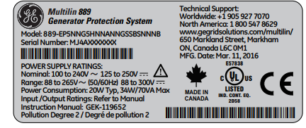
Product Identification
The product identification label is located on the side panel of the 889. This label indicates
the product model, serial number, and date of manufacture.
Figure 2-1: Product Label
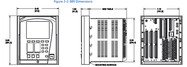
Dimensions
The dimensions (in inches [millimeters]) of the 889 are shown below. Additional dimensions
for mounting, and panel cutouts, are shown in the following sections.
Mounting
The 889 unit can be mounted two ways: standard panel mount or optional tab mounting, if
required.
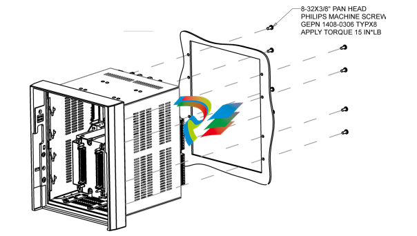
• Standard panel mounting:
From the front of the panel, slide the empty case into the cutout. From the rear of the
panel, screw the case into the panel at the 8 screw positions (see figures in Standard
panel mount section).
• Optional tab mounting:
The “V” tabs are located on the sides of the case and appear as shown in the following
figure. Use needle nose pliers to bend the retaining "V" tabs outward to about 90°. Use
caution and do not bend and distort the wall of the enclosure adjacent to the tabs. The
relay can now be inserted and can be panel wired.
Figure 2-3: “V” Tabs Located on Case Side
Standard Panel Mount The standard panel mount and cutout dimensions are illustrated below. CAUTION: To avoid the potential for personal injury due to fire hazards, ensure the unit is mounted in a safe location and/or within an appropriate enclosure. Figure 2-4: Standard panel mount
Removable Magnetic Module
IMPORTANT: Prior to the removal of the CT/VT magnetic module, all preparation steps below shall
be adhered to in order to prevent injury.
All current and voltage sources connected to the 8 Series relay must be identified
before starting the removal process.
Removal of the magnetic module from a relay installed in a power system shall only be
performed by suitably-qualified personnel.
Appropriate PPE is required based on the arc flash calculations.
CAUTION: LOTO (Lockout Tag Out) of the system is required prior to module removal/
replacement.
Follow the procedures outlined below to remove or replace the CT/VT magnetic module.
PREPARATION
1. Shut down and de-energize all systems connected to the 8 Series relay
2. Review all points in the section Cautions and Warnings.
IMPORTANT: An 8 Series relay, with the magnetic module removed, does NOT have an internal
automatic CT shorting mechanism.
CAUTION: Hazardous voltages can exist when opening the secondary circuits of live current
transformers. Make sure that in-field current transformer secondary circuits are
shorted out before making or removing any connection to the current transformer (CT)
input terminals of the device (i.e disconnection/connection of 8 Series CT Input
terminals or the internal CT/VT magnetic module).
-
 Beckhoff C6640-0040 Control Cabinet Industrial PC 7-Slot
 -
 BECKHOFF CONTROL CABINET INDUSTRIAL PC - C6930-1062-0050
 -
 Beckhoff Automation EtherCAT Terminal EK1100 EK1122
 -
 Beckhoff CP6533-0001-0060 IPC
 -
 Beckhoff EK9500 | EtherNet/IP™ Bus Coupler
 -
 Beckhoff CP6202-1047-0050 - An industrial-grade embedded panel computer.
 -
 Beckhoff C6650-0040 Industrial PC
 -
 BECKHOFF CX5230-0185 / 000119805 PLC Module
 -
 BECKHOFF EL4732 | EtherCAT Terminal, 2-channel analog output, voltage, ±10 V, 16 bit, oversampling
 -
 Beckhoff CP6202-0001-0010 Economy Built-In Panel
 -
 Beckhoff AX5206-0000-0202 Digital Compact Servo Drives 2-channel
 -
 Beckhoff CP6606-0001-0020 7-inch Economy Panel PC
 -
 Beckhoff CPU basic module CX2020-0155 + power supply module CX2100-0004
 -
 Beckhoff CP2913-000 Multi-Touch Display
 -
 Beckhoff CP6500-1012-0060 14250369 Control Cabinet
 -
 Beckhoff CP7902-0001-0000 Economy Control Panel with DVI/USB Extended interface
 -
 Beckhoff C6920-0010 Control cabinet Industrial PC
 -
 BECKHOFF C3640-0050 Build-in Industrial PCs
 -
 Beckhoff KL6023-0000 KL6023 EnOcean Wireless-Adapter
 -
 Kollmorgen AKM54G-ANC2DB00 servo motor
 -
 Kollmorgen AKD-P00606-NBCN-0000 Servo Drive
 -
Kollmorgen S200 Series S20350-VTS SERVO DRIVE
-
 KOLLMORGEN AKD-P00606-NBCC-I000 SERVO DRIVE
 -
 Kollmorgen MV65WKS-CE310/22PB Servo Drive Control Module
 -
 Kollmorgen S20360-VTS-021 Servo Drive
 -
 KOLLMORGEN CR06550 High-precision digital servo amplifier
 -
 KOLLMORGEN DBL5N01050-03S-VV0-S40 3-Phase AC Synchronous Brushless Servo Motor
 -
 KOLLMORGEN S70301-NANANA-024 SERVO DRIVE
 -
 Kollmorgen S20360-VTS S200 Series Servo Drive
 -
 Kollmorgen RBE-03011-A00 Brushless Frameless Servo Motor
 -
 KOLLMORGEN AKD-T00306-NBAN-0000 INPUT SERVO DRIVE
 -
 KOLLMORGEN S700 Servo Controller S70302-NANANA
 -
 Kollmorgen AKD-P00607-NBEC-0000 400/480VAC 4.40KVA Servo Drive.
 -
 KOLLMORGEN S70102-NANANA SERVO DRIVE
 -
 KOLLMORGEN AKM21E-ANSNEH02 PM Servo Motor & PRD-AMPE25EB-00 Servo Drive Array
 -
 KollMorgen SC1R06260 Servo Drive 1.4/2.2 KVA 115230 Vac
 -
 Kollmorgen AKD-P00306-NBAN-0000 Servo Drive
 -
Kollmorgen TTB2-2042-3052-A DC Motor Industrial Drive 5.5A 185 oz/in
-
 KOLLMORGEN SERVOSTAR 610-AS SERVO AMPLIFIER_SERVOSTAR610AS_S61001
 -
 KOLLMORGEN PRD-0016400P-10 & PRD-0016600D-30 Axis Control System Modules
 -
KOLLMORGEN Seidel DBL5N01700-03S-000-S40 Servo Motor
-
 Hirschmann RS20-1600M2T1SDAEHH03.1.02 Rail Switch
 -
 Hirschmann BRS30-24TX Industrial Rail Switch
 -
 Hirschmann RSPM20-4T14T1EV9HHS999.9.99 Managed Ethernet Switch
 -
 Hirschmann BELDEN RS40-0009CCCCSDAPHH09.0.14 / RS400009CCCCSDAPHH09014
 -
Hirschmann RS40 Rail Switch RS40-0009CCCCSDAE
-
 Hirschmann BELDEN RS30-0802T1T1SDAP / RS300802T1T1SDAP Fully Managed Layer 2 Compact Rail Switch
 -
 Hirschmann BELDEN RS20-0800M2M2SDAUHH / RS200800M2M2SDAUHH
 -
 Hirschmann EAGLE30-04022O6TT999SCCY9HSE3F Industrial Firewall Router Switch
 -
 Hirschmann RS20-1600T1T1SDAEHH09.0.14 RS20 Rail Mount Ethernet Switch
 -
 Hirschmann EAGLE0200T1T1TDDY90000HHE05.3.03 Industrial Security Router
 -
Hirschmann - BELDEN MIPP-AD-1L9P
-
 HIRSCHMANN RSPM20-4Z64Z6TV9HHS9 942 106-999 RAIL SAFETY SWITCH
 -
 HIRSCHMANN FIBEROPTIC MODULE FIP P/N: OZDFIPG3T
 -
 HIRSCHMANN RS20-1600M2M2SDAUHH Ethernet rack-mounted switch
 -
 HIRSCHMANN BELDEN RS20-0400T1T1SDAEHH04.0.01 / RS200400T1T1SDAEHH04001
 -
HIRSCHMANN MM2-4FXM3 MICE Media Module
-
HIRSCHMANN RS20-0800M2M2SDAE Industrial Ethernet Rail Switch
-
 Hirschmann RS20-2400T1T1SDAP / RS20-2400T1T1SDAPHH05.0.02
 -
 GE MLJ1005B010H00C MLJ Digital Synchromism Check
 -
 ALSTOM MICROTECH DX21-M2 Digital Excitation Controller
 -
HIRSCHMANN BRS20-1200ZZZZ-STCY99HHSES
-
 HIRSCHMANN MM3-4FXM2 MICE Media Module
 -
Hirschmann RSB20-0800T1T1SAABHH 8Port ENet Rail Switch RSB20
-
 Hirschmann MACH102-8TP Ethernet Switch
 -
 SAACKE DDZ-M marine steam pressure atomizer
 -
 SAACKE SKV-A marine rotary cup atomizer
 -
 SAACKE Seavis HMI05e
 -
 Kollmorgen MMC-SD-2.0-230 Servo Drive 100-240VAC 2KW 10A Output 3PH 100-240VAC
 -
 Kollmorgen Servo drive CR10550
 -
 Kollmorgen AKD-P01207-NACN-0054 Servo Driver
 -
 Kollmorgen S406M-CA-036 Servostar
 -
.png) Kollmorgen AKD-B02407-NAAN-0000 Digital Servo Drive
Kollmorgen AKD-B02407-NAAN-0000 Digital Servo Drive -
 Kollmorgen SERVOSTAR S406AM-CA Digital Servo Drive
 -
 KOLLMORGEN SERVOSTAR 603-AS SERVO AMPLIFIER_SERVOSTAR603AS_S60301
 -
Kollmorgen S700 Servo Controller (S70602-NANANA-NA)
-
 Kollmorgen MPK411 controller
 -
 KOLLMORGEN MMC-SD-1.3-460-D Smart Drive
 -
 KOLLMORGEN AKM21C-CKB2AA-00 / AKM21CCKB2AA00 Servomotor
 -
 BECKHOFF AX5106-0000-0200 | Digital Compact Servo Drives 1-channel
 -
 BECKHOFF C3620-0000 INDUSTRIAL COMPUTER (MOTORSHELVES)
 -
 Beckhoff EK1960-0000 TwinSAFE Compact Controller
 -
 Beckhoff C6930-0050 Control Cabinet Industrial PC
 -
 Beckhoff CP7711-0001-0030 Industrial Computer Detection
 -
 Beckhoff CX1001-0111 Embedded PC CPU Module
 -
 Beckhoff C6017-0020 | Ultra-compact Industrial PC
 -
 Beckhoff EK1322 | 2-port EtherCAT P junction with feed-in
 -
 Beckhoff CP2219-0010 Panel
 -
 BECKHOFF C6015-0020 ULTRA COMPACT INDUSTRIAL PC
 -
 BECKHOFF CX2030-0120/Standard CPU Module Embedded PC Windows PLC controller
 -
 Beckhoff CP7721-1090-0020 Panel PC
 -
 Beckhoff PC CPU Module CX5130-0175
 -
 Beckhoff C6920-0050 Control Cabinet
 -
 Beckhoff EL6631 EtherCAT 2-Port Communication Interface, Profinet RT Controller
 -
 Beckhoff CP6202-0001-0060 touch screen panel PC
 -
 Beckhoff CP3916-1002-0000 Multi-Touch Control Panel
 -
 Beckhoff EP1809-0021 | EtherCAT Box, 16-channel digital input, 24 V DC, 3 ms, M8Preferred type
 -
 Beckhoff CX8190 PLC Embedded Industrial PC Ethernet Controller
 -
 Beckhoff CX2100-0914 Power Supply for External
 -
 Beckhoff Automation CP6906-0001-0000 HMI
 -
 Beckhoff EP7342-0002 Module
 -
 Beckhoff CX1020-0112 / CX1100-0910 / CX1020-N010 / CX1100-0003 Windows CPU
 -
 Beckhoff EP7211-0034 EtherCAT Box 1 Channel Motion Interface
 -
 Beckhoff C6240-0030 Control cabinet Industrial PC
 -
 beckhoff motherboard CB1052-0004 CB1052-0004
 -
 Beckhoff AX2006-AS Servo Drive / Variable Frequency Drive
 -
BECKHOFF CP6207-0001-0020 NSMP
-
 Beckhoff C6930-1142-0060 Industrial Computer
 -
 Beckhoff FC7501-0000 interface card
 -
 Beckhoff CX5140-0175 Embedded PC PLC CPU CX5140 Industrial Controller
 -
 Beckhoff CP7802-1100-0010: High-End IP65 Control Panel with DVI/USB Extended Interface
 -
BECKHOFF CP3716-1058-0010 CONTROL PANEL
-
 Beckhoff AX8108-0000 Single-Axis Module
 -
 Beckhoff CU8851-0000 | USB extension, USB Extended 2.0 receiver box
 -
Beckhoff C6017-0030 | Ultra-compact Industrial PC
-
 Beckhoff CX1001-0120/CX10010120.cx1000-n001.cx1000-n000 System Overview
 -
 Beckhoff CPU Module CX5140-0155/4GB CPU Module
 -
 Beckhoff CP6533-0001-005: Built-in Panel PC with High-Definition Multi-Touch Control
 -
 Beckhoff EL5042 | EtherCAT Terminal, 2-channel encoder interface, BiSS® C
 -
 Beckhoff C6920-1080-0040: Premium Control Cabinet Industrial PC
 -
 Beckhoff C6920-0060 | Control cabinet Industrial PC
 -
 Beckhoff Embedded-PC CX5010-1121
 -
 Beckhoff CB3050-0010 Mainboard Motherboard
 -
 Beckhoff PLC module CX1020-0000 Basic CPU module (service phase)
 -
 Beckhoff CP7812-1056-0010 15" Multitouch Display Control Panel
 -
 Beckhoff CX5120-0115 /2GB Controller Module
 -
 Beckhoff CP7201-1000-0000 Industrial Panel PC
 -
 Beckhoff Servo Motor AM8061-0JH1-0000


