
SAMSUNG SSAS-PRO SPTB-DO dedicated digital output terminal board
SAMSUNG SSAS-PRO SPTB-DO is a dedicated digital output terminal board engineered for marine automation, ship power management, and industrial panel wiring within the Samsung SSAS-Pro framework.
It acts as an organized electrical interface between SSAS-Pro digital output modules (such as the SPDO-16.
SPDO-24. or SPRDO-16) and field-side actuators like solenoid valves, contactors, alarm horns, and status lamps.
The SPTB-DO simplifies panel wiring layout, isolates high-current field circuits, and provides easily accessible terminal test points for online maintenance and signal verification.
Technical Table
| Specification | Parameter Details |
| Manufacturer / Series | Samsung Heavy Industries / SSAS-Pro Automation Series |
| Model | SPTB-DO (Digital Output Terminal Board) |
| Module Compatibility | Connects to SPDO-16, SPDO-24, and SPRDO-16 digital output modules |
| Terminal Clamp Type | Vibration-resistant screw-clamp or spring-cage terminals |
| Supported Wire Gauge | 0.2 mm² to 2.5 mm² (AWG 24 to AWG 12) |
| Operating Voltage Rating | Up to 250V AC / 30V DC (Load dependent) |
| Max Current Capacity | 2A per channel terminal (Max module total load limits apply) |
| Module Interconnect | Multi-pin heavy-duty ribbon cable or pre-formed harness connector |
| Test Access Points | Integrated probe points adjacent to each channel terminal |
Environmental Tolerance Conditions
Operating Temperature: -15°C to +55°C
Storage Temperature: -25°C to +70°C
Relative Humidity: 5% to 95% (non-condensing)
Vibration Resistance: Certified to major marine classification society standards (DNV, ABS, LR, KR, NK) for severe engine room vibration.
Corrosion Protection: PCB traces coated with protective conformal varnish to withstand humid salt-spray atmospheres.
Operating Instructions
DIN Rail Mounting: Snap the SPTB-DO module securely onto a standard 35mm DIN rail inside the control cabinet.
Interconnect Cable Connection: Attach the dedicated multi-core cable from the SPTB-DO board directly to the output connector on the target SPDO or SPRDO card.
Field Load Termination: Strip field wire ends (approx. 7–8 mm), insert into the corresponding output channel terminals, and tighten to specified torque.
Inductive Suppression: For inductive loads (solenoid coils, relay coils), ensure flyback diodes (DC) or RC snubbers (AC) are installed across the load terminals to prevent back-EMF spikes.
Fault Diagnosis
Output Indicator Off / Field Load Inactive: Check logic signal status from the output module; inspect interconnect cable for loose pin connections or bent pins.
Blown Fuse / Open Output Channel: Inspect connected field device (solenoid coil or relay) for internal short circuits or current draw exceeding 2A per channel.
Intermittent Load Operation: Check terminal screws for loosening caused by persistent engine room vibration; verify proper wire stripping depth.
Related Models of the Same Series
SPTB-DI: Terminal Board for Digital Input Modules (SPDI Series)
SPTB-AI: Terminal Board for Analog Input Modules (SPAI / SPRI Series)
SPTB-AO: Terminal Board for Analog Output Modules (SPAO Series)
SPDO-16 / SPDO-24: Transistor Digital Output Modules
SPRDO-16: Heavy-Duty Relay Digital Output Module
SPDI-16 / SPDI-24: Discrete Digital Input Signal Acquisition Modules
Storage Conditions
Keep stored inside anti-static protective packaging in a clean, dust-free indoor facility.
Maintain storage temperatures between -25°C and +70°C with non-condensing relative humidity below 95%.
Protect from direct UV exposure, corrosive chemical fumes, salt spray, and physical shock.
| User name | Member Level | Quantity | Specification | Purchase Date |
|---|



-
 VIBRO-METER VM600Mk2/ VM600 RPS6U rack power supplies
 -
 VIBRO-METER VM600Mk2/ VM600 ABE056 slimline rack
 -
 VIBRO-METER VM600Mk2 RLC16Mk2 relay modules
 -
 VIBRO-METER VM600Mk2 MPC4Mk2 + IOC4Mk2 machinery protection and condition monitoring modules
 -
 VIBRO-METER VM600Mk2 CPUMMk2 + IOCNMk2 rack controller and communications interface module
 -
 VIBRO-METER VM600Mk2 CPUMMk2 + IOCNMk2 rack controller and communications interface module
 -
 ADLINK PCI/PCIe-7300A, cPCI-7300 32-CH 80 MB/s High-Speed Digital I/O Cards
 -
 ADLINK cPCI-7248/7249R 48-CH DIO & Timer/Counter Cards
 -
 ADLINK PCI-7230/7233/7234. LPCI/LPCIe/cPCI-7230 32-CH Isolated DIO Cards
 -
 ADLINK cPCI-6965 Series Value 6U CompactPCI® Intel® Core™2 Duo
 -
 ADLINK cPCI-6910 Series 6U CompactPCI® Dual-Core Intel® Xeon® Processor LV / ULV Universal Blade
 -
 ADLINK CPCI-6670 6U CompactPCI Low Power Pentium® III SBC
 -
 ADLINK cPCI-6625/6 Series 6U CompactPCI® PlusIO blade with Intel® Core™ i7/i3 Processor
 -
 ADLINK 3U CompactPCI CPU Modules
 -
 ADLINK CM-435 Extreme Rugged™ PC/104 Single Board Computer
 -
 ADLINK PCI-8254/8258 DSP-based 4/8-axis Advanced Motion Controllers
 -
 ADLINK NuPRO-E43 PICMG® 1.3 Full-Size LGA1151 with 6th/7th Generation Intel® Core™ i7/i5/i3
 -
 ADLINK DLAP-211-JNX/DLAP-211-JT2/ DLAP-211-Nano
 -
 Hirschmann RS30-1602O6O6SDAE compact OpenRail managed Ethernet switches
 -
Hirschmann RS30-0802O6O6SDAE Ethernet switch
-
 Hirschmann RS20-1600T1T1SDAE Management-type Ethernet switch
 -
 Hirschmann OCTOPUS 24M Limited Availability/Passive
 -
 Hirschmann MSP30-24040SCZ9MRHHE3A
 -
 Hirschmann MAR1040-4C4C4C4C9999SMMHRHHXX.X. Gigabit Ethernet Switch configurator
 -
 Hirschmann Industrial Ethernet Rail Switch SPIDER II, SPIDER II Giga, SPIDER II PoE
 -
 Hirschmann Industrial Ethernet Firewall EAGLE One
 -
 Hirschmann Industrial Security Router EAGLE20/30
 -
 Hirschmann Description and operating instructions RS2-xTX/xFX EEC
 -
 Basler Electric DECS-200 Digital Excitation Control System
 -
 Basler Electric GENERATOR PROTECTION SYSTEM BE1-GPS100
 -
 Jaquet FT3000 Speed measurement system
 -
 Hirschmann Industrial Ethernet Ruggedized Switch MACH1000 Family
 -
 Basler Electric BESTCOMSPlus®
 -
 ETEL AccurET MODULAR 300 EA-P2M-300-xxxxxA controller
 -
 Basler Electric ES Series Protection Relays
 -
 ABB Multifunction Protection and Switchbay Control Unit REF542plus
 -
 EMERSON AMS 2140 Machinery Health Analyzer
 -
 Hirschmann Industrial Ethernet Rail Switch RS20 Basic Family
 -
 GE Grid Solutions P40U Px40 USB Adaptor
 -
 ABB ontinuous Gas Analyzers AO2000 Series AO2040CU Ex Central Unit in Category 2G
 -
 ABB Advance Optima AO2000 Series Continuous gas analyzers Models AO2020. AO2040
 -
 Advance Optima Module Uras 14
 -
 SAACKE control optimization
 -
 SAACKE se@vis efficiency monitor
 -
 SAACKE se@vis pro
 -
 SAACKE se@vis eco
 -
 SAACKE se@vis compact
 -
 HIRSCHMANN Industrial ETHERNET Switch MICE MS20/MS30
 -
 HIRSCHMANN MICE Media modules
 -
 Kongsberg GL-10 Level Switch
 -
 B&R ACOPOSinverter P74 frequency converter
 -
 Beckhoff CX2020 | Basic CPU module (service phase)
 -
 Beckhoff CX1010 | Basic CPU module (service phase)
 -
 Beckhoff CX5120 | Embedded PC with Intel Atom® E3815
 -
 Beckhoff CP69xx-xxxx-0010 | Economy built-in Control Panel with DVI/USB Extended interface
 -
 Beckhoff CP29xx-0000 | Multi-touch built-in Control Panel with DVI/USB Extended interface
 -
 SAACKE Monoblock Rotary Cup Burner SKVJ-M
 -
 ABB Plantguard Fault Tolerant Technology Architecture and Software
 -
 OMRON H8PR-8/H8PR-8P H8PR-16/H8PR-16P H8PR-24/H8PR-24P Rotary Positioner
 -
 ABB PFSA107-Z42 DTU Stressometer Digital Transmission Unit
 -
 Nidec Mentor MP
 -
 IBA ibaNet-E
 -
 IBA FO Connection to Reflective Memory
 -
 IBA FO Connection to Siemens Systems
 -
 IBA Interface Cards For Fiber Optic Connections
 -
 IBA Field and Drive Buses
 -
 IBA ibaPADU-S Modular System
 -
 IBA ibaMAQS
 -
 STUCKE SYMAP®ARC
 -
 STUCKE SYMAP®R
 -
 STUCKE SYMAP®Compact
 -
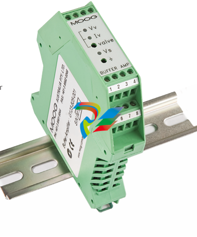 MOOG G123-825-001 BUFFER AMPLIFIER
 -
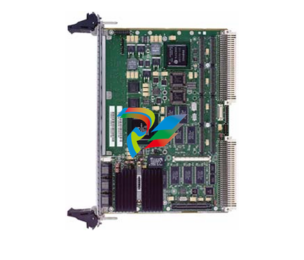 Motorola MVME5100 Series VME Processor Modules
 -
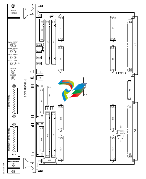 Motorola MVME162 Embedded Controller
 -
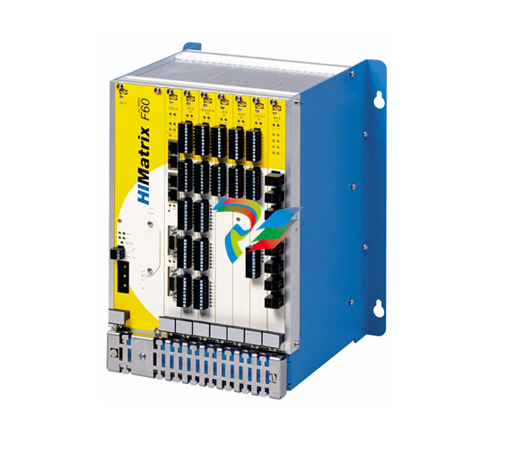 HIMatrix Safety-Related Controller System Manual for the Modular Systems
 -
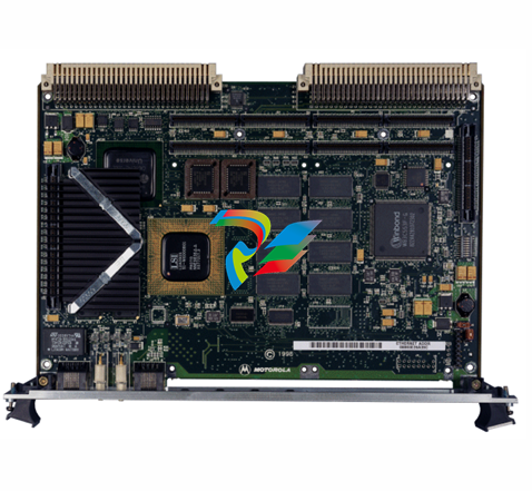 Motorola MVME2400 Series VME Processor Module
 -
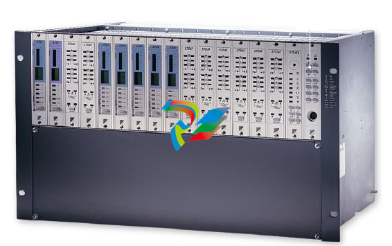 Sieger System 57
 -
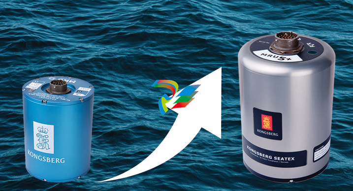 KONGSBERG MRU product line continuation
 -
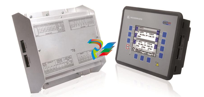 Woodward easYgen-3100/3200 Genset Control for Multiple Unit Operation
 -
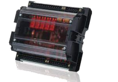 Woodward MFR 300 Multifunction Relay / Measuring
 -
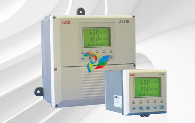 ABB AX410, AX411, AX413, AX416, AX418, AX450, AX455 and AX456 Single and dual input analyzers for low level conductivity
 -
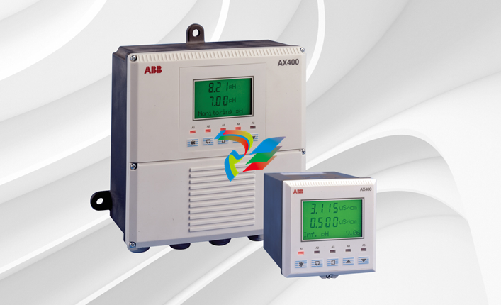 ABB AX410, AX411, AX416, AX450 and AX455 Single and dual input analyzers
 -
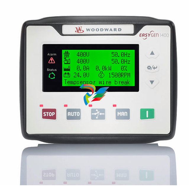 Woodward easYgen-1400 Technical Manual Genset Control
 -
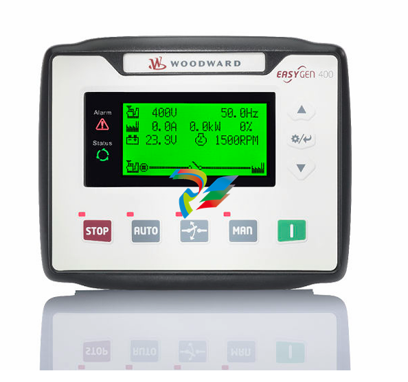 Woodward easYgen-400 Operation Manual Genset Control
 -
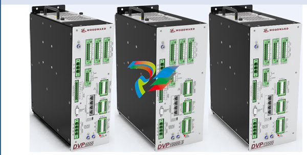 Woodward High Output Digital Valve Positioner (DVP)DVP5000/DVP10000/DVP12000
 -
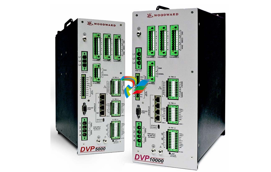 Woodward High Output Digital Valve Positioner DVP5000 and DVP10000
 -
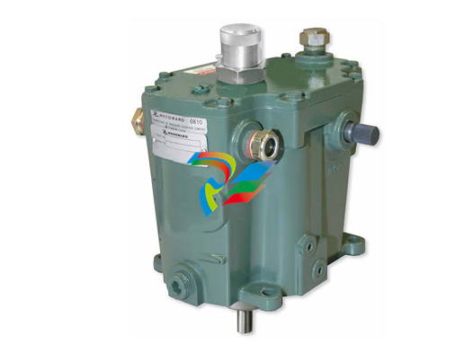 Woodward TG611-13/-17 Overspeed Test Device Conversion Kit
 -
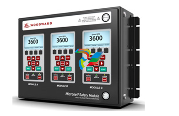 Woodward MicroNet Safety Module (MSM)
 -
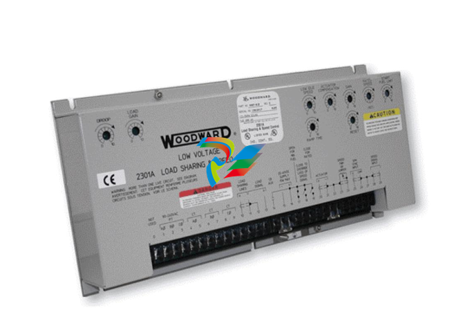 Woodward 2301A Electronic Load Sharing and Speed Control 9905/9907 Series
 -
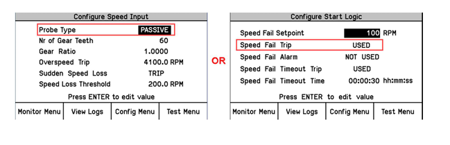 Woodward-Service Bulletin 01671
 -
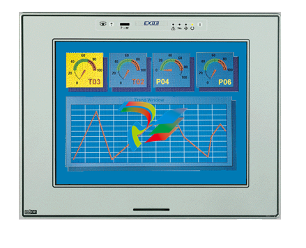
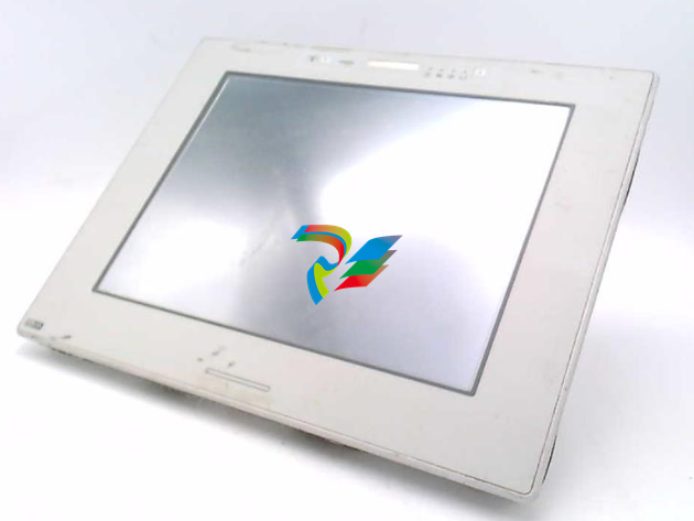 UniOP eTOP40B 12.1” TFT color display
 -
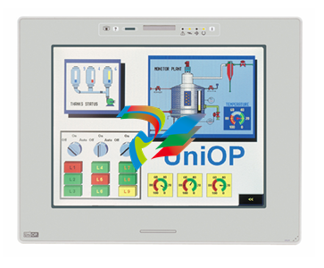
 UniOP eTOP40 TFT Color display
 -
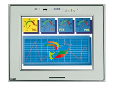
 UniOP eTOP33B 10.4” TFT color display
 -
 UniOP eTOP33C eTOP33-0050 Resistive touchscreen
 -
UniOP eTOP30. eTOP32 eTOP32-0050 Human-machine interface equipment
-
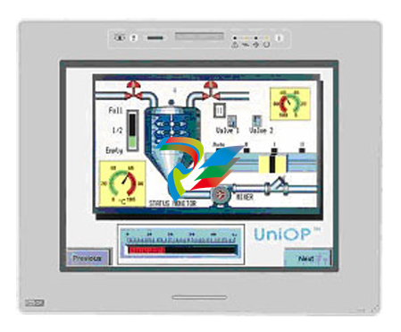 UniOP eTOP20B and eTOP21B eTOP20B-0050
 -
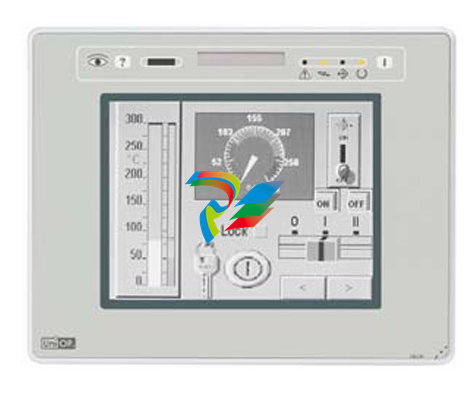 UniOP eTOP12 eTOP12-0050 Advanced human-machine interface equipment
 -
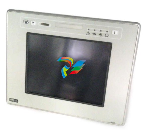 UniOP eTOP11 eTOP11-0050 HMI
 -
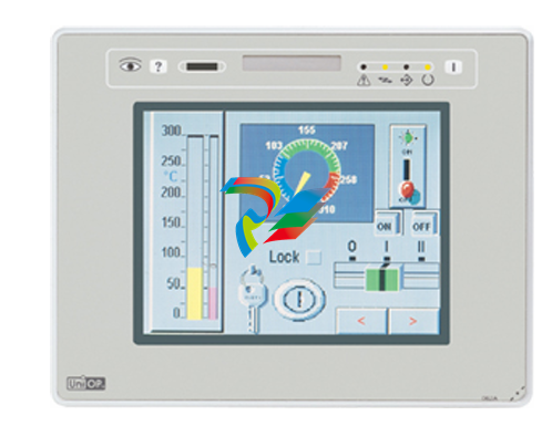 UniOP eTOP06C HMI
 -
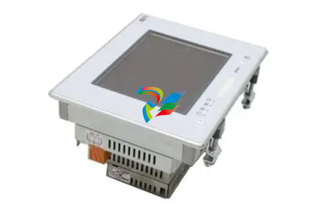 UniOP eTOP06 HMI
 -
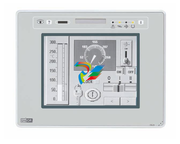 UniOP eTOP05EB eTOP05EB-DF45 HMI
 -
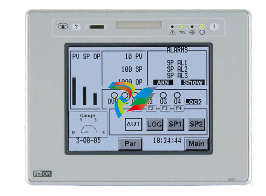 UniOP eTOP05. eTOP05P Human-machine interface equipment
 -
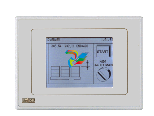 UniOP eTOP03 eTOP03-0046
 -
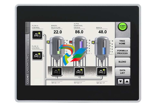 UniOP eTOP507 507U2P1 eTOP Series 500 Human-Machine Interface
 -
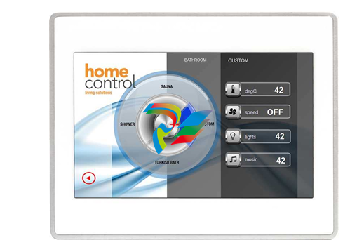 UniOP eTOP307
 -
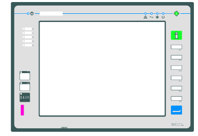 UniOP ETT-VGA Human-machine interface touch unit
 -
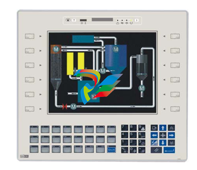 UniOP ePAD32B, ePAD33B and ePAD33BT ePAD33B-0350
 -
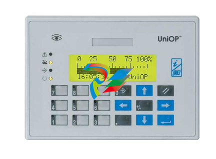 UniOP ePAD05 and ePAD06
 -
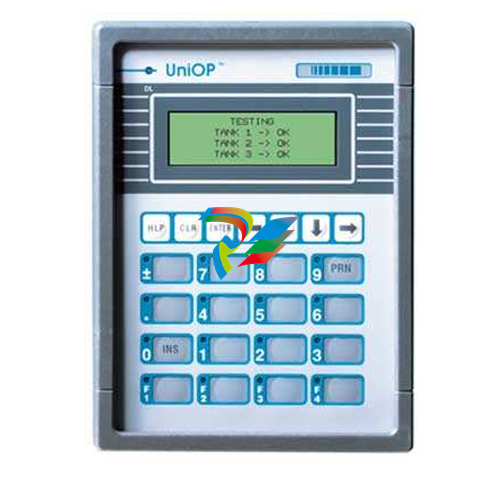 UniOP CP02R-04 Human-machine interface
 -
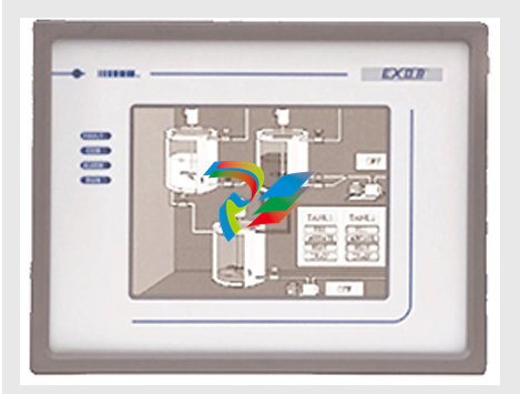 UniOP ERT-16 - Industrial PLC Workstation
 -
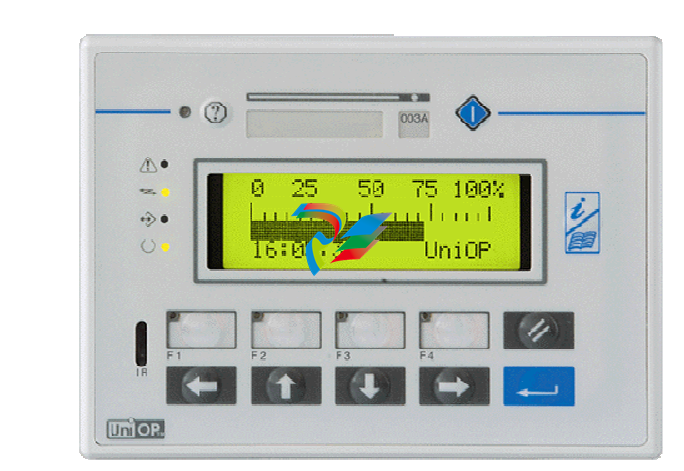 UniOP ePAD03 and ePAD04
 -
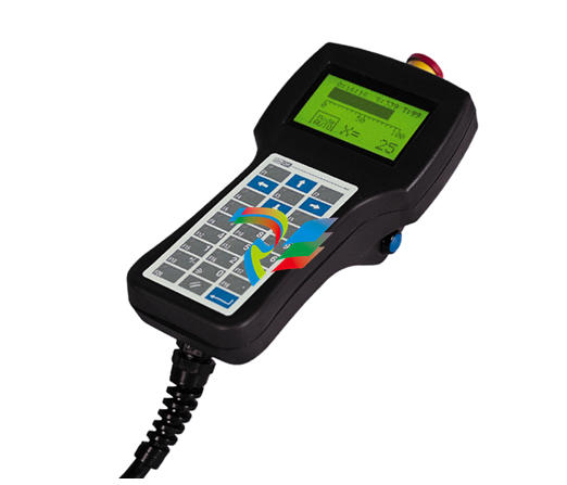 UNIOP EPALM10-DA71 state-of-the-art handheld HMI
 -
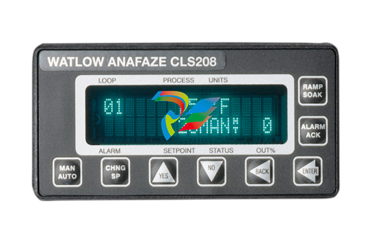 Watlow SERIES CLS200 SPECIFICATION SHEET
 -
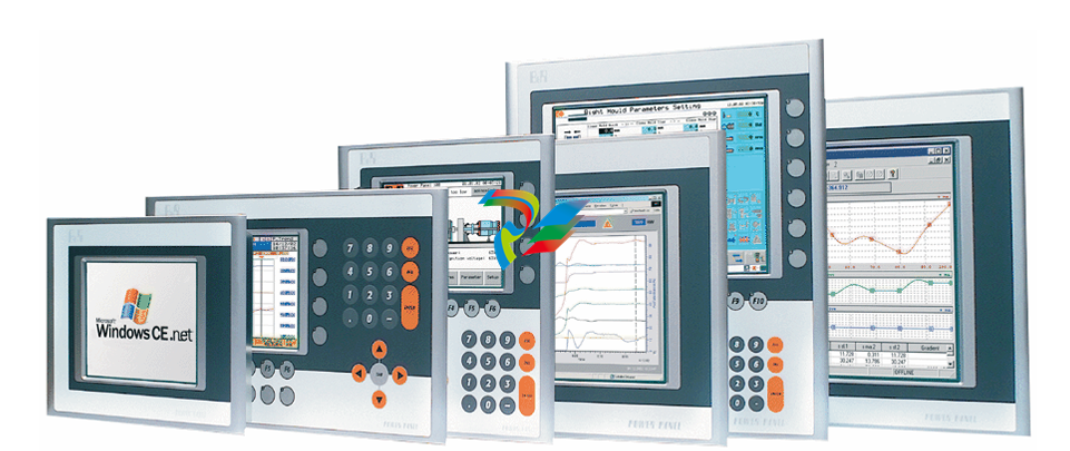 Detailed Explanation of B&R Power Panel 300/400: The Core of Industrial Automation Control
 -
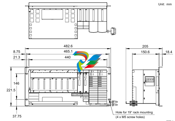 YOKOGAWA Models ANB10S, ANB10D, ANR10S, ANR10D Node Units (for FIO)
 -
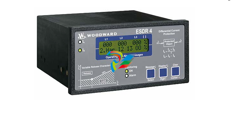 Woodward ESDR 4 Current Differential Protection Relay
 -
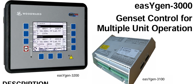 Woodward easYgen-3000 Genset Control for
 -
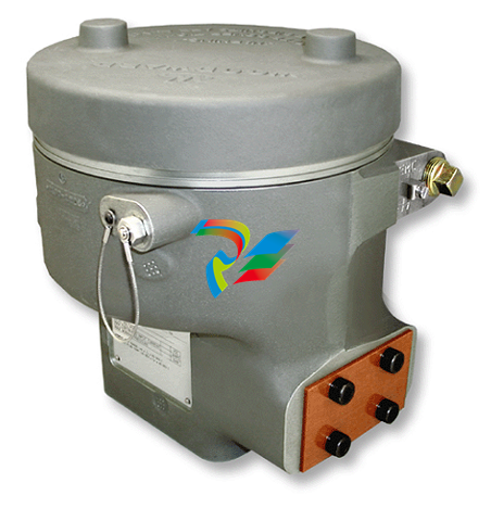 Woodward CPC-II Current-to-Pressure Converter
 -
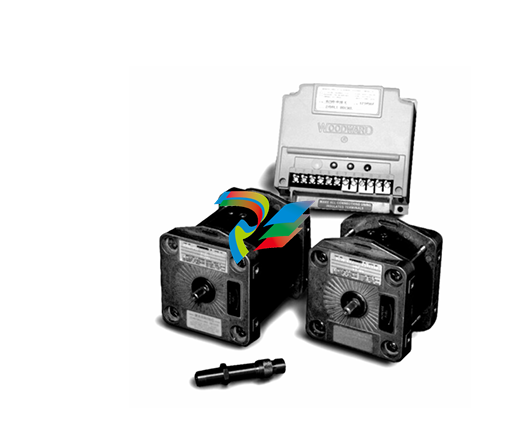 Woodward 8290-189-EPG-installation-manual 8290-044
 -
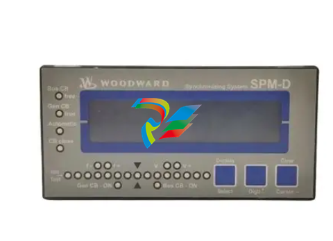 Woodward Product Change Notification 06946A
 -
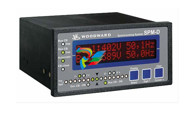 Woodward Product Change Notification 06912
 -
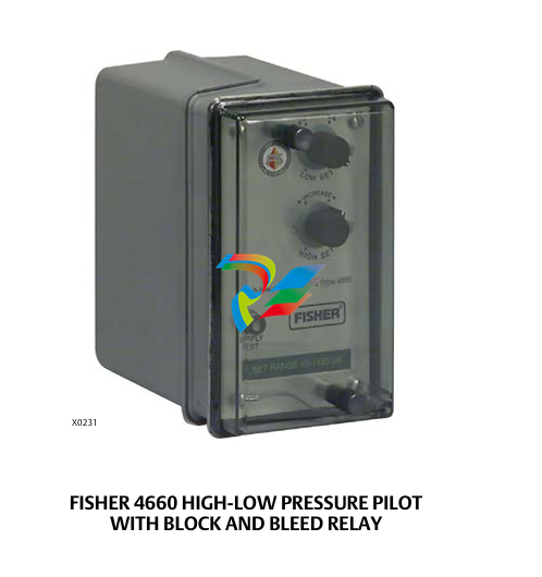 Fisher™ 4660 High-Low Pressure Pilot
 -
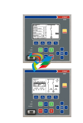 Flexible digital protection and control equipment SYMAP®
 -
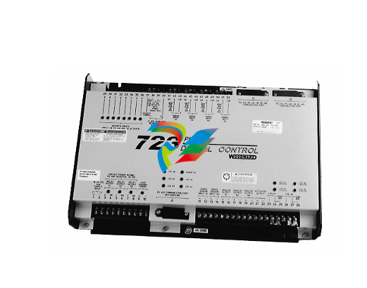 Woodward 723PLUS Digital Control
 -
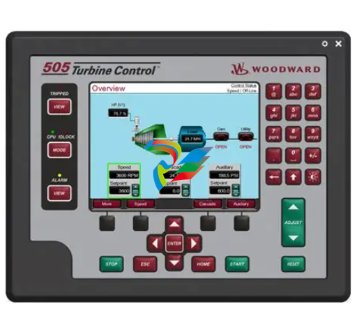 Woodward 505 Digital Controller For steam turbineses
 -
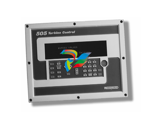 Woodward 85018V2 505E Digital Governor for Extraction Steam Turbines
 -
Woodward 85018V1 Turbine Control Parameters
-
Woodward 26871 505 Enhanced Digital Control for Steam Turbines


