
ABB ACS850-04 Drive Modules: Hardware Manual Summary
ABB ACS850-04 Drive Modules: Hardware Manual Summary
This document serves as the hardware manual for ABB ACS850-04 drive modules, covering models from 160 to 560 kW (200 to 700 hp). It provides essential information for planning, installation, operation, maintenance, and technical specifications, ensuring safe and efficient use of the drive modules.
Introduction and Safety Instructions
The manual is intended for personnel involved in planning cabinet assembly, electrical installation, and providing end-user instructions for mechanical installation, cabling, and maintenance. It emphasizes strict adherence to safety instructions to prevent physical injury, death, or damage to equipment. Key safety warnings include:
Only qualified electricians are permitted to install and maintain the drive.
Always disconnect main power and wait 5 minutes for capacitors to discharge before working on the drive, motor, or motor cable.
Verify zero voltage with a multimeter before commencing work.
Do not work on control cables when power is applied to the drive or external control circuits.
Avoid insulation or voltage withstand tests on the drive.
Be aware of dangerously high voltages on motor cable and brake control terminals.
The Safe Torque Off function does not remove voltage from main and auxiliary circuits.
Proper grounding of the drive, motor, and adjoining equipment is crucial for safety and EMC.
For permanent magnet motors, ensure the motor cannot rotate and disconnect it before working on the drive, as a rotating PM motor can energize the drive's intermediate circuit.
Handle the heavy drive module carefully using lifting lugs and support legs to prevent overturning.
Beware of hot surfaces on heatsinks.
Prevent dust from entering the drive during installation.
Handle fiber optic cables by the connector, not the cable itself, and avoid touching fiber ends.
Wear a grounding wrist band when handling printed circuit boards due to their sensitivity to electrostatic discharge.
Do not run the motor over its rated speed, as overvoltage can damage or explode capacitors.
Ensure the motor and driven equipment are suitable for the drive's full speed range before operation.
Avoid activating automatic fault reset functions if dangerous situations can occur.
Control the motor using the control panel keys or I/O board commands, not an AC contactor.
Product Overview and Hardware Description
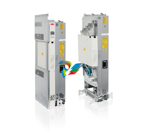
The ACS850-04 is a drive module designed for controlling asynchronous AC induction motors, permanent magnet motors, and ABB synchronous reluctance motors (SynRM motors). Its main circuit comprises an AC choke, rectifier, DC link, inverter, and an optional brake chopper (+D150) that dissipates surplus energy to a brake resistor during deceleration.
The standard unit features:
Lifting lugs and fastening brackets for installation.
Input and output cable connection busbars.
A circuit board compartment.
Main cooling fans.
Retractable support legs.
A control unit (JCU) with slots for optional I/O extension, encoder/resolver interface, and fieldbus adapter modules.
Optional selections include cabling panels (+H381 or +H383), DC busbars (+H356), various control panel and control unit configurations (e.g., +J400, +J410, +P905 for internal control unit), fieldbus adapter modules (e.g., PROFIBUS DP, PROFINET IO), I/O extension modules, and specialized control programs (e.g., Crane control program, SynRM control program).
Planning the Cabinet and Electrical Installation
Detailed guidance is provided for cabinet installation and electrical connections:
Cabinet Requirements: Use a sturdy cabinet that protects against contact, meets dust and humidity requirements, and has sufficient air inlet/outlet gratings for cooling.
Layout Planning: Design a spacious layout for easy installation and maintenance, considering cooling air flow, clearances, and cable support structures. Control boards should be placed away from main circuit components and hot parts.
Grounding: Ensure proper grounding of the drive module to the cabinet's PE busbar, either through fastening points or a separate grounding conductor.
EMC Planning: Minimize holes in the cabinet, ensure good galvanic connection between steel panels (welding or conductive EMC strips), and use 360° high-frequency grounding for cable shields at lead-throughs to suppress electromagnetic disturbances.
Cooling: Ensure sufficient ventilation of the installation site, adequate free space around components, and proper air inlet/outlet design to prevent hot air recirculation.
Cable Selection and Routing: Dimension input power and motor cables according to local regulations, using symmetrical shielded motor cables. Route motor cables away from other cable routes, crossing at right angles if necessary. All control cables must be shielded.
Protections: Install a hand-operated input disconnecting device. Protect the drive and input power cable with fuses (ultrarapid aR fuses or UL-recognized Class T/L fuses). The drive protects the motor cable and motor against short-circuits and thermal overload. For multiple motors, use separate circuit breakers/fuses for each motor.
Motor Compatibility: Use asynchronous AC induction motors, permanent magnet motors, or ABB SynRM motors. Ensure motor insulation system withstands maximum peak voltage at motor terminals, and consider optional du/dt filters, common mode filters (+E208), or insulated N-end bearings for protection.
Safety Functions: Implement Emergency Stop, Safe Torque Off, and ATEX-certified Safe Motor Disconnection functions as required.
Bypass Connection: If bypassing is needed, use mechanically or electrically interlocked contactors to prevent simultaneous closure. Never connect supply power to drive output terminals directly.
Brake Resistors: For high-capacity braking, optional brake choppers (+D150) and external resistors can be used. Select components based on braking power and heat dissipation capacity. Resistors must be installed outside the drive module in a well-cooled, non-flammable area.
-
 Hirschmann RS20-1600M2T1SDAEHH03.1.02 Rail Switch
 -
 Hirschmann BRS30-24TX Industrial Rail Switch
 -
 Hirschmann RSPM20-4T14T1EV9HHS999.9.99 Managed Ethernet Switch
 -
 Hirschmann BELDEN RS40-0009CCCCSDAPHH09.0.14 / RS400009CCCCSDAPHH09014
 -
Hirschmann RS40 Rail Switch RS40-0009CCCCSDAE
-
 Hirschmann BELDEN RS30-0802T1T1SDAP / RS300802T1T1SDAP Fully Managed Layer 2 Compact Rail Switch
 -
 Hirschmann BELDEN RS20-0800M2M2SDAUHH / RS200800M2M2SDAUHH
 -
 Hirschmann EAGLE30-04022O6TT999SCCY9HSE3F Industrial Firewall Router Switch
 -
 Hirschmann RS20-1600T1T1SDAEHH09.0.14 RS20 Rail Mount Ethernet Switch
 -
 Hirschmann EAGLE0200T1T1TDDY90000HHE05.3.03 Industrial Security Router
 -
Hirschmann - BELDEN MIPP-AD-1L9P
-
 HIRSCHMANN RSPM20-4Z64Z6TV9HHS9 942 106-999 RAIL SAFETY SWITCH
 -
 HIRSCHMANN FIBEROPTIC MODULE FIP P/N: OZDFIPG3T
 -
 HIRSCHMANN RS20-1600M2M2SDAUHH Ethernet rack-mounted switch
 -
 HIRSCHMANN BELDEN RS20-0400T1T1SDAEHH04.0.01 / RS200400T1T1SDAEHH04001
 -
HIRSCHMANN MM2-4FXM3 MICE Media Module
-
HIRSCHMANN RS20-0800M2M2SDAE Industrial Ethernet Rail Switch
-
 Hirschmann RS20-2400T1T1SDAP / RS20-2400T1T1SDAPHH05.0.02
 -
 GE MLJ1005B010H00C MLJ Digital Synchromism Check
 -
 ALSTOM MICROTECH DX21-M2 Digital Excitation Controller
 -
HIRSCHMANN BRS20-1200ZZZZ-STCY99HHSES
-
 HIRSCHMANN MM3-4FXM2 MICE Media Module
 -
Hirschmann RSB20-0800T1T1SAABHH 8Port ENet Rail Switch RSB20
-
 Hirschmann MACH102-8TP Ethernet Switch
 -
 SAACKE DDZ-M marine steam pressure atomizer
 -
 SAACKE SKV-A marine rotary cup atomizer
 -
 SAACKE Seavis HMI05e
 -
 Kollmorgen MMC-SD-2.0-230 Servo Drive 100-240VAC 2KW 10A Output 3PH 100-240VAC
 -
 Kollmorgen Servo drive CR10550
 -
 Kollmorgen AKD-P01207-NACN-0054 Servo Driver
 -
 Kollmorgen S406M-CA-036 Servostar
 -
.png) Kollmorgen AKD-B02407-NAAN-0000 Digital Servo Drive
Kollmorgen AKD-B02407-NAAN-0000 Digital Servo Drive -
 Kollmorgen SERVOSTAR S406AM-CA Digital Servo Drive
 -
 KOLLMORGEN SERVOSTAR 603-AS SERVO AMPLIFIER_SERVOSTAR603AS_S60301
 -
Kollmorgen S700 Servo Controller (S70602-NANANA-NA)
-
 Kollmorgen MPK411 controller
 -
 KOLLMORGEN MMC-SD-1.3-460-D Smart Drive
 -
 KOLLMORGEN AKM21C-CKB2AA-00 / AKM21CCKB2AA00 Servomotor
 -
 BECKHOFF AX5106-0000-0200 | Digital Compact Servo Drives 1-channel
 -
 BECKHOFF C3620-0000 INDUSTRIAL COMPUTER (MOTORSHELVES)
 -
 Beckhoff EK1960-0000 TwinSAFE Compact Controller
 -
 Beckhoff C6930-0050 Control Cabinet Industrial PC
 -
 Beckhoff CP7711-0001-0030 Industrial Computer Detection
 -
 Beckhoff CX1001-0111 Embedded PC CPU Module
 -
 Beckhoff C6017-0020 | Ultra-compact Industrial PC
 -
 Beckhoff EK1322 | 2-port EtherCAT P junction with feed-in
 -
 Beckhoff CP2219-0010 Panel
 -
 BECKHOFF C6015-0020 ULTRA COMPACT INDUSTRIAL PC
 -
 BECKHOFF CX2030-0120/Standard CPU Module Embedded PC Windows PLC controller
 -
 Beckhoff CP7721-1090-0020 Panel PC
 -
 Beckhoff PC CPU Module CX5130-0175
 -
 Beckhoff C6920-0050 Control Cabinet
 -
 Beckhoff EL6631 EtherCAT 2-Port Communication Interface, Profinet RT Controller
 -
 Beckhoff CP6202-0001-0060 touch screen panel PC
 -
 Beckhoff CP3916-1002-0000 Multi-Touch Control Panel
 -
 Beckhoff EP1809-0021 | EtherCAT Box, 16-channel digital input, 24 V DC, 3 ms, M8Preferred type
 -
 Beckhoff CX8190 PLC Embedded Industrial PC Ethernet Controller
 -
 Beckhoff CX2100-0914 Power Supply for External
 -
 Beckhoff Automation CP6906-0001-0000 HMI
 -
 Beckhoff EP7342-0002 Module
 -
 Beckhoff CX1020-0112 / CX1100-0910 / CX1020-N010 / CX1100-0003 Windows CPU
 -
 Beckhoff EP7211-0034 EtherCAT Box 1 Channel Motion Interface
 -
 Beckhoff C6240-0030 Control cabinet Industrial PC
 -
 beckhoff motherboard CB1052-0004 CB1052-0004
 -
 Beckhoff AX2006-AS Servo Drive / Variable Frequency Drive
 -
BECKHOFF CP6207-0001-0020 NSMP
-
 Beckhoff C6930-1142-0060 Industrial Computer
 -
 Beckhoff FC7501-0000 interface card
 -
 Beckhoff CX5140-0175 Embedded PC PLC CPU CX5140 Industrial Controller
 -
 Beckhoff CP7802-1100-0010: High-End IP65 Control Panel with DVI/USB Extended Interface
 -
BECKHOFF CP3716-1058-0010 CONTROL PANEL
-
 Beckhoff AX8108-0000 Single-Axis Module
 -
 Beckhoff CU8851-0000 | USB extension, USB Extended 2.0 receiver box
 -
Beckhoff C6017-0030 | Ultra-compact Industrial PC
-
 Beckhoff CX1001-0120/CX10010120.cx1000-n001.cx1000-n000 System Overview
 -
 Beckhoff CPU Module CX5140-0155/4GB CPU Module
 -
 Beckhoff CP6533-0001-005: Built-in Panel PC with High-Definition Multi-Touch Control
 -
 Beckhoff EL5042 | EtherCAT Terminal, 2-channel encoder interface, BiSS® C
 -
 Beckhoff C6920-1080-0040: Premium Control Cabinet Industrial PC
 -
 Beckhoff C6920-0060 | Control cabinet Industrial PC
 -
 Beckhoff Embedded-PC CX5010-1121
 -
 Beckhoff CB3050-0010 Mainboard Motherboard
 -
 Beckhoff PLC module CX1020-0000 Basic CPU module (service phase)
 -
 Beckhoff CP7812-1056-0010 15" Multitouch Display Control Panel
 -
 Beckhoff CX5120-0115 /2GB Controller Module
 -
 Beckhoff CP7201-1000-0000 Industrial Panel PC
 -
 Beckhoff Servo Motor AM8061-0JH1-0000
 -
 BECKHOFF CP6503-0001-0050 Built-in Panel PC
 -
Beckhoff CP3919-0010 Display G190ETN01.2 19" PCT V04. Multi-touch Control Panel
-
 Beckhoff CX5110-0112-9020/000368201 Embedded PC Intel Atom Processor
 -
 Beckhoff AX8206-0000 Dual-Axis Module
 -
Beckhoff Nail Operating Terminal CP7032-1031-0010
-
Beckhoff AM8042-0EH1-0000 Servomotor 4.10 Nm (M0), F4 (87 mm)
-
 Beckhoff EK9300 Beckhoff CPU Module
 -
Beckhoff CP3224-0020 Multitouch-Panel-PC
-
 Beckhoff CP2712-0000 12.1" 24VDC Touch Screen WMD0
 -
 BECKHOFF CX5240-0195 / 0000289234 Embedded PC 40 GB CFast Card
 -
 Beckhoff CP6932-1000-0000 Control Panel
 -
 BECKHOFF CX5120-0121 PLC Module
 -
 Beckhoff EL3218 | EtherCAT Terminal, 8-channel analog input
 -
Beckhoff C6640-0050 | Control cabinet Industrial PC
-
 Beckhoff Cx5130-0120/4GB Embedded-PC
 -
 BECKHOFF CX2030-0122 PLC PROCESSOR
 -
 BECKHOFF CX5020-0122 Controller Module
 -
 Beckhoff CP3915-0000 Multitouch Panel
 -
 BECKHOFF EL3014 | EtherCAT Terminal
 -
 BECKHOFF Industrial Computer c6920-1057-0030
 -
 Beckhoff CX5130-0141/4GB CX5130-0141 Embedded PC
 -
 Beckhoff C6240-1052-0040 4-086-06-3073 Industrial Computer
 -
 Beckhoff CX5140-0135 /4GB High-Performance Embedded Industrial PC
 -
 Beckhoff C6515-1001-0000 Industrial PC
 -
 Beckhoff AX5103-0000-0200 - Digital Compact Servo Drives
 -
 Beckhoff CX2030-0130-1003/4GB Basic CPU module
 -
 Beckhoff AX8620-0000 Power Supply Module
 -
 Beckhoff CX9020-0111 module with
 -
 Beckhoff EL7332 PLC Module
 -
 BECKHOFF CP7709-0001-0020 HMI
 -
 Beckhoff CX5120-0155/2GB Embedded PC
 -
 BECKHOFF CP7037-1037-0010 OPERATOR INTERFACE TOUCHSCREEN
 -
 Beckhoff EK9000 | ModbusTCP/UDP Bus Coupler
 -
 Beckhoff Touch Panel Screen CP6020 -0000-0000
 -
 Beckhoff CX2020-0121 Module FAST Shipping
 -
 Beckhoff CX2030-0125 Basic CPU Module
 -
 Beckhoff CP3918-0000 Multi-Touch 18.5" Control Panel
 -
 Automotion LC4A00010 DC BL Motor Control, ATS, Sub Assy, SCP, 115VAC,
 -
 500T-115VAC - VAS ENGINEERING - DORIC 500 SERIES DIGITAL TEMP INDICATOR
 -
 Honeywell X-DCS2000/EN Digital Integrated System Manager 50/60Hz 100-240V #4
 -
 Kollmorgen S60600 Servostar600 606-Fan 4 kVA, 6 A, 3 X 230 - 480 V


