
GEInstallation and Maintenance Manual
Copyright 1995. Bently Nevada, LLC.
All rights reserved.
The information contained in this document is subject to change without notice.
The following are trademarks of General Electric Company in the United States and other
countries:
Bently Nevada, System 1, Keyphasor
The following are trademarks of the legal entities cited:
Velostat is a trademark of 3M Company.
Windows is a tradmemark of Microsoft Corporation.
Modbus is a trademark of Modbus-IDA.
Notice:
This manual does not contain all the information required to operate and maintain
the product. Refer to the following manuals for other required information.
3500 Monitoring System Rack Configuration and Utilities Guide
(129777-01)
• guidelines for using the 3500 Rack Configuration software for setting the operating
parameters of the module
• guidelines for using the 3500 test utilities to verify that the input and output
terminals on the module are operating properly
3500 Monitoring System Computer Hardware and Software Manual
(128158-01)
• instructions for connecting the rack to 3500 host computer
• procedures for verifying communication
• procedures for installing software
• guidelines for using Data Acquisition / DDE Server and Operator Display Software
• procedures and diagrams for setting up network and remote communications
3500 Field Wiring Diagram Package (130432-01)
• diagrams that show how to hook up a particular transducer
• lists of recommended wiring
Operation and Maintenance Manuals for all the modules installed in the
rack
Product Disposal Statement
Customers and third parties, who are not member states of the European Union, who are
in control of the product at the end of its life or at the end of its use, are solely
responsible for the proper disposal of the product. No person, firm, corporation,
association or agency that is in control of product shall dispose of it in a manner that is
in violation of any applicable federal, state, local or international law. Bently Nevada LLC
is not responsible for the disposal of the product at the end of its life or at the end of its
use.
1. Receiving and Handling Instructions
This will be a short overview of the entire section.
1.1 Receiving Inspection
Visually inspect the system for obvious shipping damage. If you detect shipping
damage, file a claim with the carrier and submit a copy to Bently Nevada, LLC.
1.2 Handling and Storage Considerations
Proper handling and storing of printed circuit boards is extremely critical. Circuit
boards contain devices that are susceptible to damage when exposed to
electrostatic charges. Damage caused by obvious mishandling of the board will
void the warranty. To avoid damage, observe the following precautions in the
order given.
Application Advisory
Machinery protection will be lost when
you remove all power from the rack.
• Do not discharge static electricity onto the circuit board. Avoid tools or
procedures that would subject the circuit board to static damage.
Some possible causes of static damage include ungrounded soldering
irons, nonconductive plastics, and similar materials.
• Use a suitable grounding strap (such as 3M Velostat® No. 2060) to
ground yourself before handling or performing maintenance on a
printed circuit board.
• Transport and store circuit boards in electrically conductive bags or
foil.
• Use extra caution during dry weather. Relative humidity less than 30%
tends to multiply the accumulation of static charges on any surface.
When performed properly, you may remove modules from or install modules into
the rack while power is applied to the rack. Refer to << Section reference to
“Module Installation in section 4 >> for the proper procedure.
2. General Information
Monitoring and computerized vibration information systems provide the
information you need to assess the mechanical condition of rotating and
reciprocating machinery. These systems continuously measure and monitor
various supervisory parameters and provide crucial information for early
identification of machinery problems such as imbalance, misalignment, shaft
crack, and bearing failures. As such, these systems are an efficient and effective
means of satisfying plant management, engineering, and maintenance concerns
for:
• Increasing plant safety by minimizing the occurrence of hazardous
conditions or catastrophic failures.
• Improving product quality by minimizing process variances caused by
improperly operating equipment.
• Maximizing plant availability by servicing only those machines that
require it and providing more efficient turnarounds.
• Reducing plant operating costs by minimizing unplanned shutdowns
and by making more efficient use of maintenance resources.
For protection of critical machinery, we highly recommend that you permanently
install continuous monitoring systems. The term "protection" means that the
system can shut down machinery on alarm, without human interaction. These
systems include applicable transducers, each with its own dedicated monitoring
circuitry and alarm setpoints. The 3500 Monitoring System is the newest addition
to the family of continuous monitoring systems offered by Bently Nevada, LLC.
2.1 3500 Monitoring System
The 3500 is a full-feature monitoring system whose design incorporates the latest
in proven processor technology. In addition to meeting the above stated criteria,
the 3500 adds benefit in the following areas:
• Enhanced operator information
• Improved integration to plant control computer
• Reduced installation and maintenance cost
• Improved reliability
• Intrinsic Safety (IS) option
The following sections discuss these benefits in more detail.
2.1.1 Enhanced Operation Information
The 3500 design includes features to both enhance the operator's information
and present this information so that the operator may easily interpret it. These
features include:
• Improved data set
- Overall amplitude
- Probe gap voltage
- 1X amplitude and phase
- 2X amplitude and phase
- Not 1X amplitude
• Windows®-based Operator Display Software
• Data displayed at multiple locations
2.1.2 Improved Integration to Plant Control Computer
The 3500 improves integration to the plant control computer with:
• Communication Gateways supporting multiple protocols
• Time synchronized vibration and process information
2.1.3 Reduced Installation and Maintenance Costs
The 3500 system provides the following cost-saving features:
• Reduced cabling costs
• Downward product compatibility
• Improved space utilization
• Easier configuration
• Reduced spare parts
• Improved serviceability
2.1.4 Improved Reliability
The 3500 offers several features to improve system reliability.
• Redundant power supplies available
• Triple Modular Redundant (TMR) monitors and relay cards available
2.1.5 Intrinsic Safety Option
If you wish to monitor equipment that is located in hazardous atmospheres, the
3500 Monitoring System has a range of I/O modules with internal zener barriers.
These modules provide an Intrinsically Safe interface between the 3500 rack and
the transducers located in the hazardous area.
2.1.6 Multiple Output Interfaces
You can conveniently adjust monitor options (such as full scale ranges,
transducer inputs, recorder outputs, alarm time delays, alarm voting logic, and
relay configuration) in the field via software. Modular system design employs
plug-in components which allow easy servicing and expansion.
The following three independent interfaces are available with the 3500 system:
• Data Manager Interface (Transient Data Interface External or Dynamic
Data Interface External)
• Configuration/Data port
• Communications Gateway (support for Programmable Logic
Controllers, Process Control Computers, Distributed Control Systems,
and PC-based Control Systems)
These interfaces allow you to easily view monitored parameters and their
statuses in the following ways:
• System 1® Software
• Bently Nevada™ 3500 Operator Display Software
• Remote display panel
• DCS or PLC display
Convenient front panel coaxial connectors provide dynamic transducer signals
and allow you to connect diagnostic or predictive maintenance instruments.
2.2 Common Features
The common features of the modules in the 3500 rack include hot insertion or
removal of modules and external and internal termination of the wiring.
2.2.1 Hot Insertion or Removal of Modules
When performed properly, you can remove and replace any module while the
system is under power without affecting the operation of any unrelated modules.
If the rack has 2 power supplies, removing or inserting a power supply will not
disrupt the operation of the 3500 rack. See <<Section reverence: “Module
Installation in section 4 >> for the proper procedure.
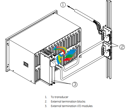
2.2.2 External and Internal Termination
External termination uses multi-conductor cables to connect the I/O modules to
the terminal blocks. These blocks simplify connecting many wires to the rack in
tight areas. External termination is not available on I/O modules with internal
zener barriers
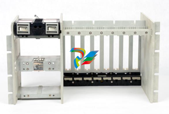
3500 System Components
The 3500 Monitoring System consists of modules that fit into a rack. Figure 2-3
shows a full-size 3500 system rack and system components. Note that the fullsize rack has 14 monitor slot positions. The Mini-rack (not shown) is similar, but
has 7 monitor slot positions to the right of the power supplies and Rack Interface
Module.
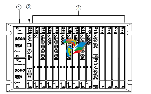
1. 1 or 2 power supplies
2. Rack Interface Module (standard, Transient Data Interface, (TDI), Triple Modular Redundant (TMR) and TMR TDI)
3. Monitoring slot positions:
- Monitor module
- Keyphasor® module (2 maximum)
- Relay module
- Communication Gateway module
- Display module. For the System Face Mount you must install the Display Interface Module in Slot 15.
- 3500/04-01 Earthing Module. Intallations that use Inernal Barrier I/Os require 1 Earthing Module per rack.
Figure 2-3: 3500 Rack (Full-Size)
The following sections list the function of each module. Refer to the individual
operation and maintenance manuals for available options, detailed description,
operation and maintenance.
2.3.1 Weatherproof Housing
The weatherproof housing protects the 3500 rack from adverse environmental
effects, such as excessive moisture, dirt and grime, and even unclean air. The
weatherproof housing will not accommodate a Display Unit or VGA Display.
2.3.2 Rack
2 types of 3500 racks are available: the full-size 19-inch rack and the compact 12-
inch Mini-rack. Each rack requires you to install the Power Supplies and Rack
Interface Module (RIM) in specific locations. The full-size version offers 14
additional rack positions and the Mini-rack offers 7 additional rack positions. You
may use these positions to install any combination of modules. Both racks
support Standard (non-redundant) and Triple Modular Redundant (TMR)
configurations.
2.3.3 Power Supply
The Power Supply is a half-height module available in ac and dc versions. You
can install 1 or 2 power supplies in the rack. Each power supply can power a fully
loaded rack. When you install 2 power supplies in a rack, the supply in the lower
slot acts as the primary supply and the supply in the upper slot acts as the
backup supply. If the primary supply fails, the backup supply will provide power to
the rack without interrupting rack operation. The 3500 design allows you to
install any combination of power supply types.
Overspeed Detection and TMR Monitors require dual power supplies.
2.3.4 Rack Interface Module
The Rack Interface Module (RIM) is a full-height module that communicates with
the host (computer), a Bently Nevada™ Communication Processor, and the other
modules in the rack. The Rack Interface Module also maintains the System Event
List and the Alarm Event List. You can daisy-chain this module to the Rack
Interface Modules in other racks and to the Data Acquisition / DDE Server
Software. The 3500 Monitoring System Computer Hardware and Software Manual
shows how to daisy chain the Rack Interface Modules together. Rack Interface
Modules are available in Standard, Triple Modular Redundant and Transient Data
Interface versions.
2.3.5 Communication Gateway Module
The Communication Gateway Module is a full-height module that allows external
devices (such as a DCS or a PLC) to retrieve information from the rack and to set
up portions of the rack configuration. You can install more than one
Communication Gateway Module in the same rack. Communication Gateway
Modules are available for a variety of network protocols.
2.3.6 Monitor Module
The Monitor Modules are full-height modules that collect data from a variety of
transducers. You can install any combination of Monitor Modules in the 3500
rack.
2.3.7 Relay Module
Relay Modules provide relays that you can configure to close or open based on
channel statuses from other monitors in the 3500 rack. Relay modules are
available in 4-channel, 16-channel, and 4-channel Triple Modular Redundant
(TMR) versions.
The TMR Relay Module is a half-height 4-channel module that operates in a TMR
system. 2 half-height TMR Relay Modules must operate in the same slot. If you
remove the upper or lower Relay Module or the system declares one of the
modules as Not OK, then the other Relay Module will control the Relay I/O Module.
2.3.8 Keyphasor® Module
The Keyphasor Module is a half-height module that provides power for the
Keyphasor transducers, conditions the Keyphasor signals, and sends the signals
to the other modules in the rack. The Keyphasor Module also calculates the rpm
values sent to the host (computer) and external devices (DCS or PLC) and provides
buffered Keyphasor outputs. Each Keyphasor Module supports 2 channels. You
may place up to 2 Keyphasor Modules in a 3500 rack for a maximum of 4
Keyphasor channels. If you use 2 Keyphasor Modules, you must place them in the
same full-height slot and the modules will share a common I/O module.
2.3.9 Display Module
The 3500 system offers multiple display options.
The Display Interface Module can display rack data on an LCD-based Interface
unit or a 3rd-party Modbus® based display unit.
The VGA Display Module will display rack data on certain touch screen VGA
Displays.
The Integrated PC display is a complete rack mount touch screen PC pre-loaded
with rack configuration software and display utilities.
2.3.10 Earthing Module
The Earthing Module is a full-height module that provides a low resistance
connection (must be less than 1 Ω) from the 3500 rack to the plant’s intrinsically
safe earth ground. The module operates in conjunction with the 3500 internal
zener barrier I/O modules. Your application will require 1 Earthing Module per rack
when internal barrier I/O modules are used.
2.4 Standard Rack Relay Options
You can configure the standard (or non-TMR) 3500 rack to have individual relays,
bussed relays, or a combination of individual and bussed relays.
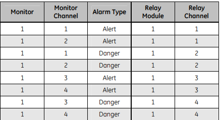
2.4.1 Individual Relays
A rack with individual relays contains 1 or more relay cards for each monitor
module. You can configure the monitor and relay modules within a 3500 rack in
many ways.
Example 1: The application uses 1 relay module 1 monitor module.
Table 2-1: 1 Relay Module Used With 1 Monitor Module
2.5 Intrinsic Safety — The 3500 Internal Barrier System
To provide Intrinsically Safe (IS) vibration and process variable monitoring, the
3500 system has a range of I/O modules with internal zener barriers. When you
install these modules in a 3500 rack with a 3500/04-01 Earthing Module, they
provide an integrated solution for explosion protection for approved Bently
Nevada transducer systems that are located within all classifications of
hazardous areas (surface industries other than mining).
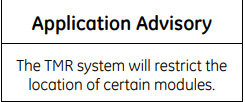
2.5.1 3500 Internal Barrier System Restrictions
• You must install 1 earthing module in each rack in the internal barrier
system. The earthing module occupies 1 slot position in the rack when it
uses Internal Barrier I/O modules.
• You must change the grounding configuration of the 3500/15 Power
Supplies from the default factory setting. See the 3500/15 Operation and
Maintenance Manual (PN 129767-01) for instructions.
• You must isolate any RS-232 connection to any 3500 module. Monitors
that support RS232 connections include Rack Interface Modules,
Communication Gateways, and the 3500/95 PC Display. See the 3500/20
Operation and Maintenance Manual (PN 129768-01) for instructions. This
restriction does not apply to RS422 and RS485 connections to the rack.
Monitors that support RS422 and/or RS485 connections include the
3500/20, 3500/90, 3500/92, 3500/93, and 3500/95.
• You must not use the 3500/94 VGA Display in internal barrier systems.
• You must not use bussed transducers, as internal barrier systems do not
allow bussed transducers. See the TMR section of this manual for more
information.
2.5.2 3500 Internal Barrier System Features
• The earthing module supports dual IS Earth connections for cables with
cross-sectional areas up to 10 mm2. This module lets you test IS Earth
continuity online.
• The design of the internal barrier I/O modules provides the 2 inches (50
mm) of separation required between safe and hazardous area field wiring.
• The connectors for safe areas and hazardous areas have different field
wiring colors (green for safe and blue for hazardous) and connector
pitches. This helps to avoid incorrect field wiring installation.
• Quick connect/disconnect connectors simplify field wiring installation and
removal.
4.3 Replacing Modules
When replacing modules, whether main or I/O, you need not remove power from
the rack if the following procedures are followed. Refer to applicable steps in the
procedures above for removing or installing a module.
4.3.1 Main Modules
This assumes that you will replace only the main module of a monitor or power
supply. Before you remove any module, refer to the applicable manual to see how
this may affect rack behavior, and to identify any special handling requirements
that you may require for personal safety.
1. If necessary, upload and save the configuration of the module to be
replaced.
2. Remove the main module from the rack.
3. Install the new main module into the rack.
4. If necessary, configure the new main module.
5. Verify operation.
4.3.2 I/O Modules
This assumes that you will replace only the I/O module of a monitor or the PIM of
a power supply. Before you remove any module, refer to the applicable manual to
see how this may affect rack behavior, and to identify any special handling
requirements that you may require for personal safety.
1. If necessary, upload and save the configuration of the module to be
replaced.
2. Remove the main module from the rack.
3. Remove the field wiring from the I/O module.
4. Remove the old I/O module from the rack.
5. Install the new I/O module into the rack.
6. Connect the field wiring to the new I/O module.
7. Install the main module into the rack.
8. If necessary, re-configure the main module.
9. Verify operation
5.1 General Maintenance Instructions
You cannot repair the boards and components inside of 3500 modules in the field.
3500 rack maintenance consists of testing module channels to verify that they
are operating correctly. You should replace modules that are not operating
correctly with a spare.
When performed properly, you may remove modules from or install modules into
the rack while power is applied to the rack. Refer to Section 3 for the proper
procedure.
The 3500 Monitoring System is a high precision instrument that requires no
calibration. The functions of the 3500 modules, however, require verification at
regular intervals. You should verify all modules in the 3500 Monitoring System at
these maintenance intervals. The procedures in the Maintenance and
Troubleshooting sections of the module manuals describe the verification and
troubleshooting process.
5.2 Choosing a Maintenance Interval
Use the following approach to choose a maintenance interval:
1. Start with an interval of 1 year and then shorten the interval if any of the
following conditions apply:
• the monitored machine is classified as critical, or
• the 3500 rack is operating in a harsh environment such as in
extreme temperature, high humidity, or a corrosive atmosphere.
2. At each interval, use the results of the previous verifications and ISO
Procedure 10012-1 to adjust the interval.
-
 GE SR745-W2-P1-G1-HI-A-L-R-E Feeder protection relay
 -
 GE IS230TNDSH2A Discrete Output Relay Module Brand
 -
 GE Fanuc IS200TDBSH2ACC Mark VI Terminal Board Brand
 -
 GE PMC-0247RC-282000 350-93750247-282000F Disk Drive
 -
GE PMC-0247RC-282000 350-93750247-282000F Disk Drive
-
 GE VMIVME-1150 Serial Communications Controller
 -
 GE VMIVME-5576 Fiber-Optic Reflective Memory with Interrupts
 -
 GE VMIC Isolated Digital Output VMIVME-2170A
 -
 GE MULTILIN 760 FEEDER MANAGEMENT RELAY 760-P5-G5-S5-HI-A20-R-E
 -
 GE IS200AEPAH1BKE IS215WEPAH2BB Printed circuit board
 -
 GE IS210BPPCH1A Mark VIe I/O Pack Processor Card
 -
 GE IS220PRTDH1A 336A4940CSP6 High-Performance RTD Input Module
 -
GE IS220PDIAH1BE 336A5026ADP4 Discrete Input Module
-
 GE IS420ESWBH3A IONET Switch Module
 -
 GE 516TX 336A4940DNP516TX 16-port Ethernet switch
 -
 GE EVMECNTM13 Embedded control module
 -
 GE EVPBDP0001 EVPBDP032 control module
 -
 GE Hydran M2-X Enhanced Monitoring with Extended Sensor Life
 -
 GE UR6CH Digital I/O Module
 -
 GE IC695CPU315-CD Central processing unit
 -
 GE 531X305NTBAMG1 DR Terminal Board
 -
 GE 531X305NTBALG1 NTB/3TB Terminal Board 531X Series
 -
 GE 531X305NTBAJG1 NTB/3TB Terminal Board.
 -
 GE 531X305NTBAHG1 NTB/3TB Terminal Board 531X
 -
 GE 531X305NTBAEG1 is a PCB that functions as a DR terminal board.
 -
General Electric 531X305NTBACG1 NTB/3TB Terminal Board 531X
-
 GE Digital Energy D20 Analog Input Module
 -
 GE 94-164136-001 main board Control board
 -
 GE 269 PLUS-D/O-100P-125V Digital motor relay
 -
 GALIL DMC-9940 High-performance motion controller
 -
 FUJI NP1BS-08 base plate
 -
 FUJI NP1Y32T09P1 Transistor drain type digital output module
 -
 FUJI NP1Y16R-08 Digital Output Module
 -
 FUJI NP1X3206-A High-speed digital input module
 -
 FUJI NP1AYH4I-MR current output module
 -
 FUJI NP1S-22 Power module redundancy
 -
 FUJI RPXD2150-1T servo drive module
 -
 FUJI FVR008E7S-2UX Ac frequency converter
 -
 FUJI Ac frequency converter FVR008E7S-2
 -
 FUJI FVR004G5B-2 Small general-purpose frequency converter
 -
 FUJI A50L-2001-0232 Industrial control module
 -
 FUJI A50L-001-0266#N High-performance servo amplifier
 -
 Honeywell FS7-2173-2RP Gas sensor
 -
 Honeywell 10106/2/1 Digital Input Module in Stock
 -
 FRCE SYS68K CPU-40 B/16 PLC core processor module
 -
 Foxboro FBM I/O cards PBCO-D8-009
 -
 Foxboro AD916AE Digital Control System (DCS) Module
 -
 GE SR750-P5-G5-S5-HI-A20-R-E Multilin Relay
 -
.jpg) FOXBORO H90 H90C9AA0117S Industrial Computer Workstation
FOXBORO H90 H90C9AA0117S Industrial Computer Workstation -
.jpg) FOXBORO RH928AW | I/A Series Relay Output Module
FOXBORO RH928AW | I/A Series Relay Output Module -
.jpg) Foxboro N-2AX+DIO Multi-functional input/output module
Foxboro N-2AX+DIO Multi-functional input/output module -
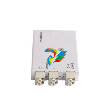
 Foxboro RH924WA FCP280 Fiber Optic Network Adapter
 -
 FOXBORO H92 Versatile Hardware Component In
 -
 Foxboro FBM218 P0922VW HART® Communication Redundant Output Interface Module
 -
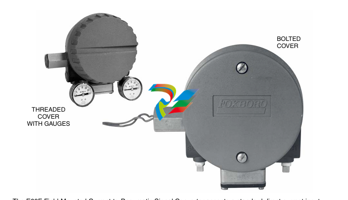
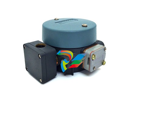 Foxboro E69F-TI2-J-R-S E69F Series Current-To-Pneumatic Signal Converter
 -
 Foxboro E69F-BI2-S Converter
 -
.jpg) Foxboro H92A049E0700 The host of the DCS control station
Foxboro H92A049E0700 The host of the DCS control station -
 Foxboro H90C9AA0117S Industrial computer workstation
 -
 Foxboro RH101AA High-performance industrial control module
 -
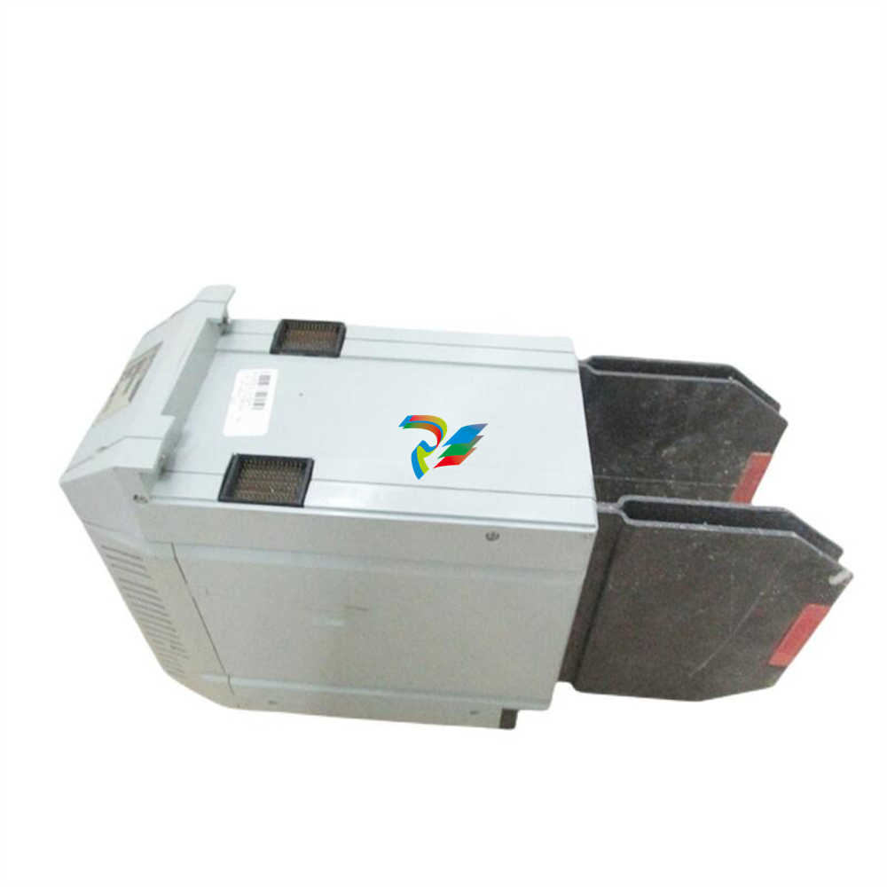
 Foxboro P0922YU FPS400-24 I/A Series Power supply
 -
.png) FOXBORO P0973LN Chassis-based managed switch with independent power supply
FOXBORO P0973LN Chassis-based managed switch with independent power supply -
.jpg) FOXBORO P0926PA Input/output module
FOXBORO P0926PA Input/output module -
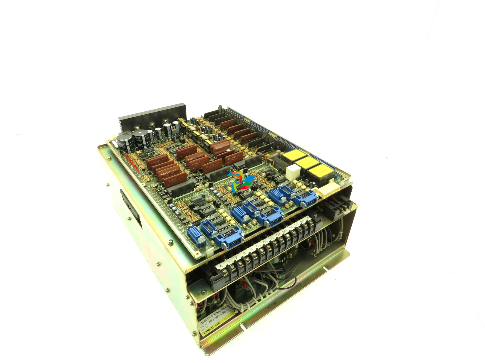 Fanuc A06B-6050-H402 3 AXIS ANALOG AC SERVO DRIVE
 -
.jpg) FOXBORO L0130AD L0130AE-0H Power module group
FOXBORO L0130AD L0130AE-0H Power module group -
_lVjBYb.jpg) FOXBORO 0399085B 0303440C+0303458A Combination Control Module
FOXBORO 0399085B 0303440C+0303458A Combination Control Module -
 FOXBORO SY-0399095E (SY-0303451D+SY-0303460E) Process control board
 -
.jpg) FOXBORO 0399071D 0303440C+0303443B Input/Output (I/O) Module
FOXBORO 0399071D 0303440C+0303443B Input/Output (I/O) Module -
.jpg) FOXBORO RH924UQ Redundant Controller module
FOXBORO RH924UQ Redundant Controller module -
 FFOXBORO E69F-TI2-S current pneumatic converter
 -
 FOXBORO FBM219 RH916RH Discrete I/O Module
 -
 FOXBORO FBM227 P0927AC Module
 -
.jpg) FOXBORO 0399144 SY-0301059F SY-1025115C/SY-1025120E I/O module
FOXBORO 0399144 SY-0301059F SY-1025115C/SY-1025120E I/O module -
.jpg) FOXBORO SY-60399001R SY-60301001RB Industrial Control Module
FOXBORO SY-60399001R SY-60301001RB Industrial Control Module -
 FOXBORO 0399143 SY-0301060R SY-1025115C SY-1025120E Combined control board
 -
 FOXBORO 873EC-JIPFGZ electrodeless conductivity analyzer
 -
 FOXBORO P0916PH (High-density HART I/O Module)
 -
 FOXBORO 870ITEC-AYFNZ-7 Intelligent Electrochemical Transmitters
 -
 FOXBORO Compact FBM240. Redundant with Readback, Discrete
 -
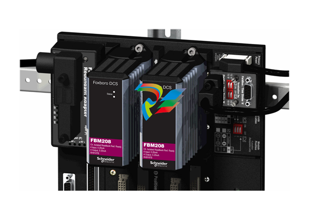 FOXBORO FBM208/b, Redundant with Readback, 0 to 20 mA I/O Module
 -
 FOXBORO FBM201e Analog Input (0 to 20 mA) Interface Modules
 -
.jpg) FOXBORO P0916WG Terminal cable
FOXBORO P0916WG Terminal cable -
 FOXBORO P0926MX 2-Port Splitter
 -
.jpg) FOXBORO AD908JQ High-Frequency Module
FOXBORO AD908JQ High-Frequency Module -
.jpg) FOXBORO AD916CC Processor module
FOXBORO AD916CC Processor module -
 Foxboro DCS FBM206 Pulse Input Module
 -
 FOXBORO FBM216 HART® Communication Redundant Input Interface Module
 -
 Foxboro p0903nu 1×8 unit sub-component module
 -
 Foxboro P0911SM Industrial control module
 -
 Foxboro CM902WM I/O module
 -
 Foxboro CM902WL Power module
 -
 Foxboro P0972VA Industrial Control Module
 -
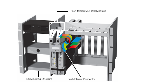
 Foxboro Z-Module Control Processor 270 (ZCP270)
 -
 Foxboro PO916JS 16-channel terminal block module
 -
 Foxboro PO911SM High-performance digital/analog input/output module
 -
 Foxboro P0972PP-NCNI Network Interface Module
 -
.jpg) FOXBORO P0971QZ controller module
FOXBORO P0971QZ controller module -
 FOXBORO P0971DP Thermal resistance input/output module
 -
 FOXBORO P0970VB Cable connector
 -
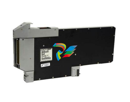
 FOXBORO P0970EJ-DNBX Dual-node bus expansion module
 -
 FOXBORO P0970BP Redundant power supply system
 -
.jpg) FOXBORO P0970BC-DNBI DeviceNet bus interface module
FOXBORO P0970BC-DNBI DeviceNet bus interface module -
.jpg) FOXBORO P0961FX-CP60S Main control CPU module
FOXBORO P0961FX-CP60S Main control CPU module -
.jpg) FOXBORO P0961EF-CP30B Network Interface Unit
FOXBORO P0961EF-CP30B Network Interface Unit -
.jpg) FOXBORO P0961CA Optical fiber local area network module
FOXBORO P0961CA Optical fiber local area network module -
.jpg) FOXBORO P0961BD-GW30B gateway processor module
FOXBORO P0961BD-GW30B gateway processor module -
.jpg) FOXBORO P0961BC-CP40B/I/A Series high-performance control processor module
FOXBORO P0961BC-CP40B/I/A Series high-performance control processor module -
FOXBORO P0960JA-CP40 High-performance control processor
-
FOXBORO P0926TM Control module
-
 FOXBORO P0916BX Termination Assembly
 -
.jpg) FOXBORO P0916AE P0916AG P0916AW Thermal resistance input type DCS card module
FOXBORO P0916AE P0916AG P0916AW Thermal resistance input type DCS card module -
 FOXBORO P0916AC FOXBORO distributed control system (DCS) compression terminal assembly
 -
.jpg) FOXBORO P0912CB High-performance interface module
FOXBORO P0912CB High-performance interface module -
.jpg) FOXBORO P0911VJ Thermal resistance input output module
FOXBORO P0911VJ Thermal resistance input output module -
.jpg) FOXBORO P0911QH-A High-precision module
FOXBORO P0911QH-A High-precision module -
 FOXBORO P0911QB-C P0911QC-C Thermal resistance input/output module
 -
 FOXBORO P0904BH P0904FH P0904HB Distributed Control system (DCS) module
 -
 FOXBORO P0903ZP P0903ZQ Embedded System Debugging Module
 -
 Foxboro P0903ZL P0903ZN Industrial power module
 -
 Foxboro P0903ZE I/A Series Fieldbus Isolator Module
 -
 FOXBORO P0903NW Industrial Control Module
 -
.jpg) FFOXBORO P0903NQ Industrial power module
FFOXBORO P0903NQ Industrial power module -
 FFOXBORO P0903AA Control Module
 -
 FOXBORO P0400DL Digital output module
 -
.jpg) FOXBORO P0400BJ Digital output module
FOXBORO P0400BJ Digital output module -
 FOXBORO GW30 industrial control module
 -
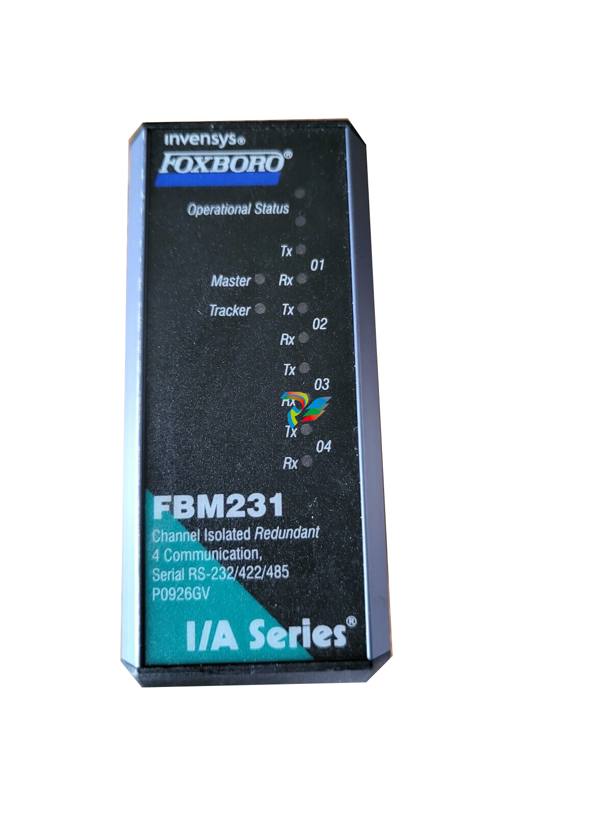 FOXBORO FBM231 Communication Output Module
 -
 FOXBORO Fieldbus Communications Module, FCM10Ef
 -
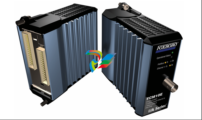 FOXBORO Fieldbus Communications Module, FCM10E


