
A-BLC Series Linear MotorsUSER MANUAL
2. Verify that the flatness of the surface to which the magnet plate is to be
mounted is 0.005 in. Total Indicator Reading (TIR) per 12.0 inches. This
specification correlates to the overall flatness requirement of 0.005 in.
(.127 mm).
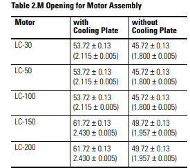
3. Prior to any component installation, verify that the opening for the
magnet plate and coil is dimensioned per Table 2.M.
Never try to place the motor coil assembly directly on the
magnet plates. Serious damage may result. Due to magnetic
attraction.
those responsible for the application and use of this motor assembly must
satisfy themselves that all necessary steps have been taken to assure that each
application and use meets all performance and safety requirements, including
any applicable laws, regulations, codes and standards.
The illustrations, charts, sample programs and layout examples shown in this
guide are intended solely for purposes of example. Since there are many
variables and requirements associated with any particular installation, Anorad
does not assume responsibility or liability (to include intellectual property
liability) for actual use based upon the examples shown in this publication.
Reproduction of the contents of this copyrighted publication, in whole or part,
without written permission of Anorad Corporation, is prohibited.
Throughout this manual we use notes to make you aware of safety
considerations:
Attention statements help you to:
• identify a hazard
• avoid a hazard
• recognize the consequences
IMPORTANT Identifies information that is critical for successful
application and understanding of the product.
Introduction
Using This Manual This motor manual is designed to help you install, integrate and start-up your
new Anorad Linear Motor. You do not have to be an expert in motion control.
However, this manual does assume you have a fundamental understanding of
basic electronics, mechanics, as well as motion control concepts and applicable
safety procedures.
The intent of this manual is to assist the user in the mechanical and electrical
installation of the Anorad LC Series Linear Motor.
Read this entire manual before you attempt to install your linear motor into
your motion system. Doing so will familiarize you with the linear motor
components and their relationship to each other and the system
After installation, check all system parameters to insure you have configured
your linear motor into your motion system properly.
Be sure to follow all instructions carefully and lastly but foremost pay special
attention to safety concerns.
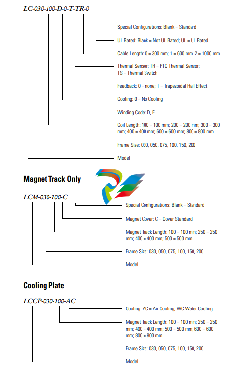
Product Description General
The LC Linear Motor Series is described in this section. Product features are
explored and the part numbering system is explained. This basic information
will help you develop an understanding of the linear motor’s basic
configuration. This configuration information is then used as the fundamental
understanding required to guide you through the rest of this manual.
Product Line Description
Anorad's LC Series of steel core linear motors represents the most advanced
linear motor technology available. The LC linear motor utilizes a unique patent
pending laminated steel core design. Coupled with the latest magnetic
materials and optimized by Finite Element Analysis (FEA), a very high force
density is achieved. The LC Linear Motors ares available in models with
continuous forces from 84.5 N to 5658 N, (19 lbf to 1272 lbf), and peak forces
from 195.7N to 9314 N, (44 lbf to 2094 lbf). Other frame sizes are available
with higher forces.
For servo drives that require commutation feedback, an optional trapezoidal
(digital) Hall effect feedback module may be attached to the front of the motor
coil. The LC may also be commutated via software. Anorad offers a full line of
compatible servo controls and drives.
Motor Features
• Steel core design for high force density
• Sinusoidal flux density and low-cog design yields smooth motion
• Robust design for heavy duty applications
• Modular magnet tracks permit unlimited travel
• Internal thermal sensor gives added motor protection
Maintenance Anorad linear motors require no maintenance when operated in a relative clean
environment. For operation in harsh and dirty environments minimal clean is
recommended every 6 months:
• Clean the metallic debris and other contaminants from the air gap. To
effectively remove the metal debris use a strip of masking tape.
Simply put a strip of tape on the magnet track an then remove it.
Keeping the magnet track clean will prevent witness marks. Witness
marks are caused by metal debris being dragged across the surface of
the stainless steel by the magnet field of the moving coil. Witness
marks have no effect on the performance of the motor.
Installation
Unpacking and Inspection Inspect motor assemblies to make certain no damage has occurred in
shipment. Any damage or suspected damage should be immediately
documented. Claims for damage due to shipment are usually made against the
transportation company. Also contact Anorad immediately for further advise.
Identify what options your linear motor is equipped with. Ensure the
information listed on the purchase order correlates to the information on the
packing slip that accompanied your motor components Verify that the quantity
of magnet plates received matches your job requirements. Inspect the
assemblies and confirm, if applicable, the presence of specified options.
ATTENTION
!
Linear Motors contain powerful permanent magnets which
require extreme caution during handling. When handing
multiple magnet plates do not allow the plates to come in
contact with each other. Do not disassemble the magnet
plates. The forces between plates are very powerful and can
cause bodily injury. Persons with pacemakers or Automatic
Implantable Cardiac Defibrillator (AICD) should maintain
a minimum distance of 12 inches from magnet assemblies.
Additionally, unless absolutely unavoidable, a minimum
distance of 5 feet must be maintained between magnet
assemblies and other magnetic/ferrous composite
materials. Use only non-metallic instrumentation when
verifying assembly dimension prior to installation (e.g.
calipers, micrometers, laser equipment, etc.)
Identifying the Linear Motor
Type
Coil Assembly (example)
1. Ensure the mounting surface to which the magnet plate is to be attached
is clear of any and all foreign material. If necessary, stone the mounting
surface (acetone or methanol may be applied as cleaning agent).
Do not clean the surface using abrasives!
4. Position the moving slide to the end of travel that you wish the cable to
exit. Making sure that the mounting face of the motor coil is clean and
free of burrs, install the motor under the slide. Select a M5 x 0.8 bolt
with a length that extends through the slide by 12 mm minimum, but
not more then 20 mm. Tighten snugly for now, bolts will be torqued
once installation is complete.
5. On the opposite end of the base, install the first magnet plate using M5
x 0.8 and 16 mm long SHCS. Non-magnetic tools and hardware
(beryllium copper, 300 series stainless steel, etc.) should be use. If not
available proceed with care since magnetic items will be attracted to the
magnet plates. Do not tighten bolts at this time. Install additional
magnet plates by placing them on the base and sliding towards the
previous install plate. Orient the plates such that the alignment holes are
toward the same side. This will ensure proper magnet polarity.
6. Move the slide, which you previously mounted motor coil to, over the
magnet plate. There may be some resistance while moving onto the
plate, this is normal. Measure the gap between the motor and magnet
using plastic shim stock. The gap should be 0.79 mm (0.031 in.) to
1.70 mm (0.067 in.). If gap is too large, add appropriate brass or stainless
steel shim between motor and slide. If gap is to small, machine the slide
or place shims under the bearing pucks.
7. Once the motor is gapped properly, install the remaining magnet plates.
8. The final alignment of the magnet plates are done with an aluminum
straight edge, and the alignment tool that was supplied with the magnet
plates. Slightly loosen the magnet plate mounting bolts, but not the ones
that are covered by the motor coil. Place the alignment tool in the holes
on each of the plates, this will properly position the pitch of the plates.
Align the edges of the plate with the aluminum straight edge and tighten
the bolts
9. Position the slide over the complete sections and continue aligning the
remainder of the plates.
10. If the area where the magnet plates are to be installed does not allow you
to use a straight edge describes above, an alternate method of aligning
plates can be done. Space the plate by using a 0.020 plastic shim between
the magnet plates, tighten the bolts, and then remove the shim.
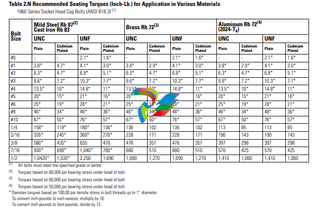
11. Once all the alignment is completed, torque all bolts to values listed in
the tables.When considering torque values for mounting hardware, take
into account the magnet plate, mounting surface and mounting
hardware. Per Table 2.N secure all assemblies in place using all
mounting holes.
ATTENTION
!
Remove alignment tool and make certain all magnet plate
mounting hardware is flush or below magnet surface to
prevent damage to the coil.
Motor/Hall Phasing and
Sequence
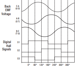
See Figure 2.15 for the standard phase and sequence relationship of the LC
series motors when phased in the specific motor direction. The Trapezoidal
Hall signals are used by a compatible three phase brushless servo drive to
perform electronic commutation. Two types of servo drive Hall-based
commutation techniques are possible, Trapezoidal Hall Mode and Encoder
(Software/Digital) Mode with Trapezoidal Hall start-up. Note: For optimal
commutation and force generation, the selected servo drive must be
compatible with the LC series phasing; and be wired to the motor correctly.
As shown in the phasing diagram:
S1 in phase with C-A Back EMF
S2 in phase with A-B Back EMF
S3 in phase with B-C Back EMF
Phase sequence = S1 leads S2 leads S3. Spacing is 120 degrees.
Figure 2.15 Motor Phasing Diagram
Back EMF Voltage vs. Hall Signals
Phasing direction = coil toward motor power cable or magnet assembly away
from power cable as shown in Figure 2.16.
ATTENTION
!
Incorrect Motor/Hall wiring can cause runaway conditions.
-
 Hirschmann RS20-1600M2T1SDAEHH03.1.02 Rail Switch
 -
 Hirschmann BRS30-24TX Industrial Rail Switch
 -
 Hirschmann RSPM20-4T14T1EV9HHS999.9.99 Managed Ethernet Switch
 -
 Hirschmann BELDEN RS40-0009CCCCSDAPHH09.0.14 / RS400009CCCCSDAPHH09014
 -
Hirschmann RS40 Rail Switch RS40-0009CCCCSDAE
-
 Hirschmann BELDEN RS30-0802T1T1SDAP / RS300802T1T1SDAP Fully Managed Layer 2 Compact Rail Switch
 -
 Hirschmann BELDEN RS20-0800M2M2SDAUHH / RS200800M2M2SDAUHH
 -
 Hirschmann EAGLE30-04022O6TT999SCCY9HSE3F Industrial Firewall Router Switch
 -
 Hirschmann RS20-1600T1T1SDAEHH09.0.14 RS20 Rail Mount Ethernet Switch
 -
 Hirschmann EAGLE0200T1T1TDDY90000HHE05.3.03 Industrial Security Router
 -
Hirschmann - BELDEN MIPP-AD-1L9P
-
 HIRSCHMANN RSPM20-4Z64Z6TV9HHS9 942 106-999 RAIL SAFETY SWITCH
 -
 HIRSCHMANN FIBEROPTIC MODULE FIP P/N: OZDFIPG3T
 -
 HIRSCHMANN RS20-1600M2M2SDAUHH Ethernet rack-mounted switch
 -
 HIRSCHMANN BELDEN RS20-0400T1T1SDAEHH04.0.01 / RS200400T1T1SDAEHH04001
 -
HIRSCHMANN MM2-4FXM3 MICE Media Module
-
HIRSCHMANN RS20-0800M2M2SDAE Industrial Ethernet Rail Switch
-
 Hirschmann RS20-2400T1T1SDAP / RS20-2400T1T1SDAPHH05.0.02
 -
 GE MLJ1005B010H00C MLJ Digital Synchromism Check
 -
 ALSTOM MICROTECH DX21-M2 Digital Excitation Controller
 -
HIRSCHMANN BRS20-1200ZZZZ-STCY99HHSES
-
 HIRSCHMANN MM3-4FXM2 MICE Media Module
 -
Hirschmann RSB20-0800T1T1SAABHH 8Port ENet Rail Switch RSB20
-
 Hirschmann MACH102-8TP Ethernet Switch
 -
 SAACKE DDZ-M marine steam pressure atomizer
 -
 SAACKE SKV-A marine rotary cup atomizer
 -
 SAACKE Seavis HMI05e
 -
 Kollmorgen MMC-SD-2.0-230 Servo Drive 100-240VAC 2KW 10A Output 3PH 100-240VAC
 -
 Kollmorgen Servo drive CR10550
 -
 Kollmorgen AKD-P01207-NACN-0054 Servo Driver
 -
 Kollmorgen S406M-CA-036 Servostar
 -
.png) Kollmorgen AKD-B02407-NAAN-0000 Digital Servo Drive
Kollmorgen AKD-B02407-NAAN-0000 Digital Servo Drive -
 Kollmorgen SERVOSTAR S406AM-CA Digital Servo Drive
 -
 KOLLMORGEN SERVOSTAR 603-AS SERVO AMPLIFIER_SERVOSTAR603AS_S60301
 -
Kollmorgen S700 Servo Controller (S70602-NANANA-NA)
-
 Kollmorgen MPK411 controller
 -
 KOLLMORGEN MMC-SD-1.3-460-D Smart Drive
 -
 KOLLMORGEN AKM21C-CKB2AA-00 / AKM21CCKB2AA00 Servomotor
 -
 BECKHOFF AX5106-0000-0200 | Digital Compact Servo Drives 1-channel
 -
 BECKHOFF C3620-0000 INDUSTRIAL COMPUTER (MOTORSHELVES)
 -
 Beckhoff EK1960-0000 TwinSAFE Compact Controller
 -
 Beckhoff C6930-0050 Control Cabinet Industrial PC
 -
 Beckhoff CP7711-0001-0030 Industrial Computer Detection
 -
 Beckhoff CX1001-0111 Embedded PC CPU Module
 -
 Beckhoff C6017-0020 | Ultra-compact Industrial PC
 -
 Beckhoff EK1322 | 2-port EtherCAT P junction with feed-in
 -
 Beckhoff CP2219-0010 Panel
 -
 BECKHOFF C6015-0020 ULTRA COMPACT INDUSTRIAL PC
 -
 BECKHOFF CX2030-0120/Standard CPU Module Embedded PC Windows PLC controller
 -
 Beckhoff CP7721-1090-0020 Panel PC
 -
 Beckhoff PC CPU Module CX5130-0175
 -
 Beckhoff C6920-0050 Control Cabinet
 -
 Beckhoff EL6631 EtherCAT 2-Port Communication Interface, Profinet RT Controller
 -
 Beckhoff CP6202-0001-0060 touch screen panel PC
 -
 Beckhoff CP3916-1002-0000 Multi-Touch Control Panel
 -
 Beckhoff EP1809-0021 | EtherCAT Box, 16-channel digital input, 24 V DC, 3 ms, M8Preferred type
 -
 Beckhoff CX8190 PLC Embedded Industrial PC Ethernet Controller
 -
 Beckhoff CX2100-0914 Power Supply for External
 -
 Beckhoff Automation CP6906-0001-0000 HMI
 -
 Beckhoff EP7342-0002 Module
 -
 Beckhoff CX1020-0112 / CX1100-0910 / CX1020-N010 / CX1100-0003 Windows CPU
 -
 Beckhoff EP7211-0034 EtherCAT Box 1 Channel Motion Interface
 -
 Beckhoff C6240-0030 Control cabinet Industrial PC
 -
 beckhoff motherboard CB1052-0004 CB1052-0004
 -
 Beckhoff AX2006-AS Servo Drive / Variable Frequency Drive
 -
BECKHOFF CP6207-0001-0020 NSMP
-
 Beckhoff C6930-1142-0060 Industrial Computer
 -
 Beckhoff FC7501-0000 interface card
 -
 Beckhoff CX5140-0175 Embedded PC PLC CPU CX5140 Industrial Controller
 -
 Beckhoff CP7802-1100-0010: High-End IP65 Control Panel with DVI/USB Extended Interface
 -
BECKHOFF CP3716-1058-0010 CONTROL PANEL
-
 Beckhoff AX8108-0000 Single-Axis Module
 -
 Beckhoff CU8851-0000 | USB extension, USB Extended 2.0 receiver box
 -
Beckhoff C6017-0030 | Ultra-compact Industrial PC
-
 Beckhoff CX1001-0120/CX10010120.cx1000-n001.cx1000-n000 System Overview
 -
 Beckhoff CPU Module CX5140-0155/4GB CPU Module
 -
 Beckhoff CP6533-0001-005: Built-in Panel PC with High-Definition Multi-Touch Control
 -
 Beckhoff EL5042 | EtherCAT Terminal, 2-channel encoder interface, BiSS® C
 -
 Beckhoff C6920-1080-0040: Premium Control Cabinet Industrial PC
 -
 Beckhoff C6920-0060 | Control cabinet Industrial PC
 -
 Beckhoff Embedded-PC CX5010-1121
 -
 Beckhoff CB3050-0010 Mainboard Motherboard
 -
 Beckhoff PLC module CX1020-0000 Basic CPU module (service phase)
 -
 Beckhoff CP7812-1056-0010 15" Multitouch Display Control Panel
 -
 Beckhoff CX5120-0115 /2GB Controller Module
 -
 Beckhoff CP7201-1000-0000 Industrial Panel PC
 -
 Beckhoff Servo Motor AM8061-0JH1-0000
 -
 BECKHOFF CP6503-0001-0050 Built-in Panel PC
 -
Beckhoff CP3919-0010 Display G190ETN01.2 19" PCT V04. Multi-touch Control Panel
-
 Beckhoff CX5110-0112-9020/000368201 Embedded PC Intel Atom Processor
 -
 Beckhoff AX8206-0000 Dual-Axis Module
 -
Beckhoff Nail Operating Terminal CP7032-1031-0010
-
Beckhoff AM8042-0EH1-0000 Servomotor 4.10 Nm (M0), F4 (87 mm)
-
 Beckhoff EK9300 Beckhoff CPU Module
 -
Beckhoff CP3224-0020 Multitouch-Panel-PC
-
 Beckhoff CP2712-0000 12.1" 24VDC Touch Screen WMD0
 -
 BECKHOFF CX5240-0195 / 0000289234 Embedded PC 40 GB CFast Card
 -
 Beckhoff CP6932-1000-0000 Control Panel
 -
 BECKHOFF CX5120-0121 PLC Module
 -
 Beckhoff EL3218 | EtherCAT Terminal, 8-channel analog input
 -
Beckhoff C6640-0050 | Control cabinet Industrial PC
-
 Beckhoff Cx5130-0120/4GB Embedded-PC
 -
 BECKHOFF CX2030-0122 PLC PROCESSOR
 -
 BECKHOFF CX5020-0122 Controller Module
 -
 Beckhoff CP3915-0000 Multitouch Panel
 -
 BECKHOFF EL3014 | EtherCAT Terminal
 -
 BECKHOFF Industrial Computer c6920-1057-0030
 -
 Beckhoff CX5130-0141/4GB CX5130-0141 Embedded PC
 -
 Beckhoff C6240-1052-0040 4-086-06-3073 Industrial Computer
 -
 Beckhoff CX5140-0135 /4GB High-Performance Embedded Industrial PC
 -
 Beckhoff C6515-1001-0000 Industrial PC
 -
 Beckhoff AX5103-0000-0200 - Digital Compact Servo Drives
 -
 Beckhoff CX2030-0130-1003/4GB Basic CPU module
 -
 Beckhoff AX8620-0000 Power Supply Module
 -
 Beckhoff CX9020-0111 module with
 -
 Beckhoff EL7332 PLC Module
 -
 BECKHOFF CP7709-0001-0020 HMI
 -
 Beckhoff CX5120-0155/2GB Embedded PC
 -
 BECKHOFF CP7037-1037-0010 OPERATOR INTERFACE TOUCHSCREEN
 -
 Beckhoff EK9000 | ModbusTCP/UDP Bus Coupler
 -
 Beckhoff Touch Panel Screen CP6020 -0000-0000
 -
 Beckhoff CX2020-0121 Module FAST Shipping
 -
 Beckhoff CX2030-0125 Basic CPU Module
 -
 Beckhoff CP3918-0000 Multi-Touch 18.5" Control Panel
 -
 Automotion LC4A00010 DC BL Motor Control, ATS, Sub Assy, SCP, 115VAC,
 -
 500T-115VAC - VAS ENGINEERING - DORIC 500 SERIES DIGITAL TEMP INDICATOR
 -
 Honeywell X-DCS2000/EN Digital Integrated System Manager 50/60Hz 100-240V #4
 -
 Kollmorgen S60600 Servostar600 606-Fan 4 kVA, 6 A, 3 X 230 - 480 V


