
ABB SDCS-CON-4 Digital inputs
ABB SDCS-CON-4 Digital inputs is a kind of digital inpt module produced by ABB Company, mainly used in industrial automation control systems. The following are some advantages of this product: High reliability: ABB's products are renowned for their high quality and reliability, and SDCS-CON-4 Digital inputs is no exception. It can operate stably in various industrial environments. Flexible configuration: This module supports multiple digital input signal types, such as NPN, PNP, etc., and can be flexibly configured according to actual application requirements. Fast response time: It features a relatively fast signal response time, capable of promptly capturing and processing changes in input signals, meeting the requirements of real-time control. High precision: It can accurately detect and convert digital signals, ensuring the accuracy and stability of the control system. Easy to install and maintain: The module is compactly designed and easy to install. Meanwhile, ABB offers abundant technical support and documentation, making maintenance and troubleshooting relatively simple. Isolation protection: It usually has a signal isolation function, which can effectively prevent the influence of external interference on the system and improve the safety and reliability of the system. Strong compatibility: It has good compatibility with ABB's other automation products and various control systems, facilitating system integration and expansion. Diagnostic function: It has certain diagnostic functions and can display the working status of the module through indicator lights or other means, helping users quickly locate problems. Anti-interference ability: It can still maintain stable performance in industrial environments with strong electromagnetic interference. Modular design: The modular design makes replacement and upgrade very convenient, reducing downtime. These advantages have enabled ABB SDCS-CON-4 Digital inputs to be widely applied in the field of industrial automation
Brand: ABB Model: SDCS-CON-4 Rated Voltage: 400V Power: 800kW Product Certification: 3C Dimensions: 450, 350, 120mm Weight: 50kg Structure Form: Modular Installation Method: Control Room Installation LD Instruction Processor: Soft PLC Processing Customization It is these parameters that indicate that SDCS-CON-4 is a modular digital input device, suitable for control room installation, and supports soft PLC programming. It has specific dimensions and weights and has p
assed the 3C product certification. When purchasing or using this device, these parameters are crucial for understanding its performance and application environment. In addition, the SDCS-CON-4 module is produced by ABB and sold through multiple suppliers, such as Beijing Xinhe New Technology Development Co., Ltd. and Xiamen Amicon Technology Co., LTD. These suppliers offer technical support and services and guarantee the quality of the products
Recommend
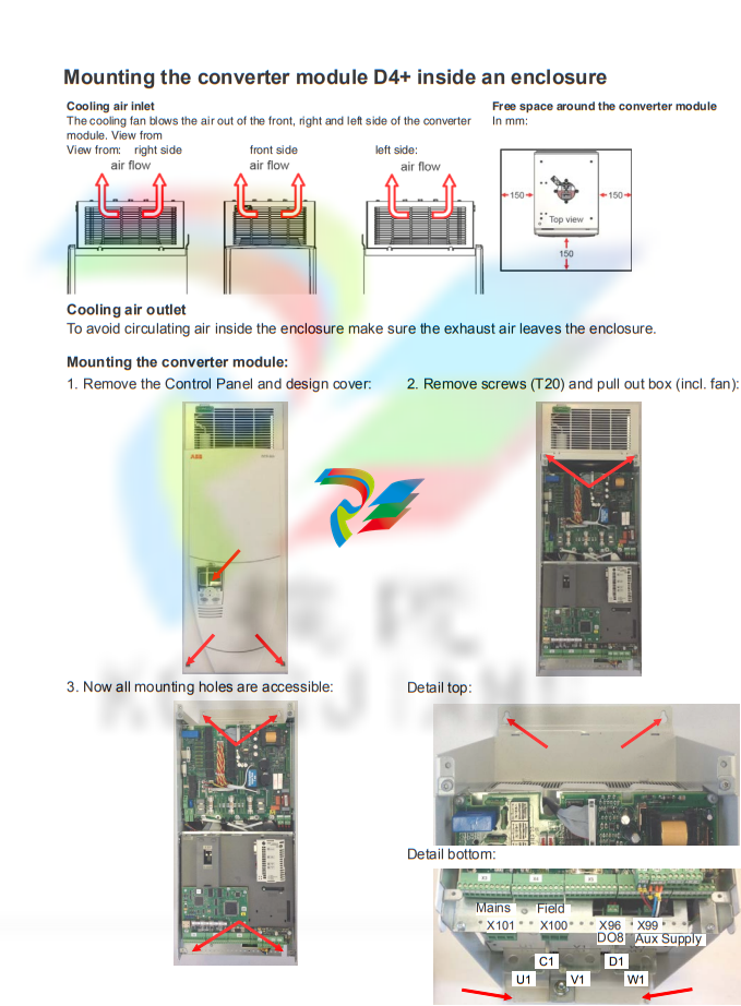
ed air entry / exit sizes in case of filters (IP22)
Size Nominal converter current [A] Air entry size [m2] Air exit size [m2] D1 20 to 140 0.22 0.11 D2 180 to 260 D3 315 to 350 D3 405 to 520 0.31 0.15 D4 610 to 1000 D4+ 1190 0.22 0.11 D5 900 to 2000 D6 1900 to 3000 0.44 0.31 D7 2050 to 5200 0.52
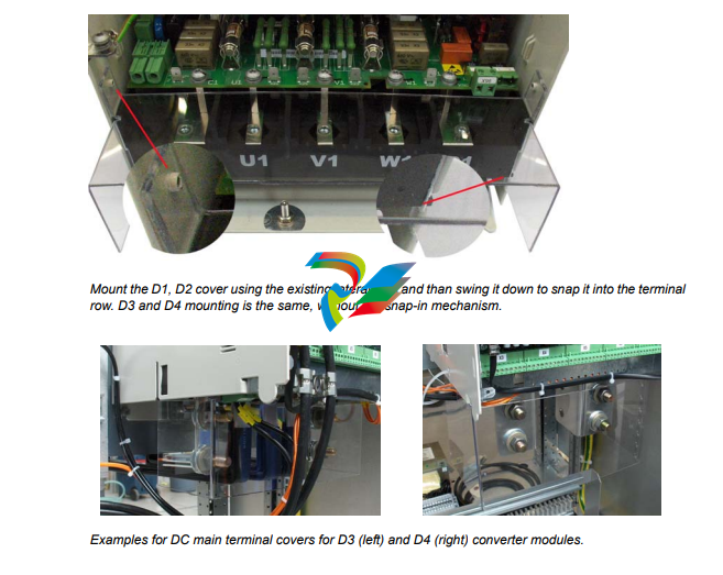
Terminal options for converter modules size D1 - D4 There are different options to protect and connect the terminals of converter modules size D1 - D4. Connection of D4 converter module DC terminals In some cases it is beneficial to use lug bars for easy DC cable connection

What this chapter contains
This chapter contains the safety instructions which you must follow when installing,
operating and servicing the drive. If ignored, physical injury or death may follow, or
damage may occur to the drive, the motor or driven equipment. Read the safety
instructions before you work on the unit.
To which products this chapter applies
The information is valid for the whole range of the product DCS800, the converter
modules DCS800-S0x size D1 to D7, field exciter units DCF80x, etc. like the Rebuild
Kit DCS800-R00-9xxx.
Use of warnings and notes
There are two types of safety instructions throughout this manual: warnings and
notes. Warnings caution you about conditions which can result in serious injury or
death and/or damage to the equipment. They also tell you how to avoid the danger.
Notes draw attention to a particular condition or fact, or give information on a
subject. The warning symbols are used as follows:
Dangerous voltage warning warns of high voltage which can cause
physical injury and/or damage to the equipment.
General danger warning warns about conditions, other than those
caused by electricity, which can result in physical injury or death and/or
damage to the equipment.
Electrostatic sensitive discharge warning warns of electrostatic
discharge which can damage the equipment.
Safety instructions
5
3ADW000194R0811 DCS800 Hardware Manual us h
Installation and maintenance work
These warnings are intended for all who work on the drive, motor cable or motor.
Ignoring the instructions can cause physical injury or death and/or damage to the
equipment..
WARNING!
• Only qualified electricians are allowed to install and maintain the drive!
• Never work on the drive, motor cable or motor when main power is applied.
Always ensure by measuring with a multimeter (impedance at least 1 Mohm)
that:
1. Voltage between drive input phases U1, V1 and W1 and the frame is
close to 0 V.
2. Voltage between terminals C+ and D- and the frame is close to 0 V.
• Do not work on the control cables when power is applied to the drive or to the
external control circuits. Externally supplied control circuits may cause
dangerous voltages inside the drive even when the main power on the drive is
switched off.
• Do not make any insulation resistance or voltage withstand tests on the drive or
drive modules.
• Isolate the motor cables from the drive when testing the insulation resistance or
voltage withstand of the cables or the motor.
• When reconnecting the motor cable, always check that the C+ and D- cables
are connected with the proper terminal.
Note:
• The motor cable terminals on the drive are at a dangerously high voltage when
the main power is on, regardless of whether the motor is running or not.
• Depending on the external wiring, dangerous voltages (115 V, 220 V or 230 V)
may be present on the relay outputs of the drive system (e.g. SDCS-IOB-2 and
RDIO).
• DCS800 with enclosure extension: Before working on the drive, isolate the
whole drive from the supply
Terminal cover according to VBG 4 regulations
For converter modules size D1 - D4 shrouds for protection against contact are
provided.
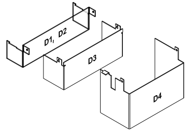 Id No. Id No. | Id No. |
| 3ADT631137P0001 | D1, D2 |
| 3ADV400208P0001 | D3 |
| 3ADV400207P0001 | D4 |
Chapter overview
This chapter contains the instructions that must be followed when selecting the
motor, cables, protections, cable routing and way of operation for the drive system.
Always follow local regulations. This chapter applies to all DCS800 converter
modules.
Attention:
If the recommendations given by ABB are not followed, the drive may experience
problems that the warranty does not cover. See also Technical Guide.
Options
Line reactors (L1)
For armature and field supply.
When thyristor converters operate, the line voltage is short-circuited during
commutation from one thyristor to the next. This operation causes voltage dips in the
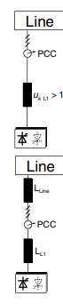
mains PCC (point of common coupling). For the connection of a power converter
system to the mains, one of the following configurations applies:
Configuration A
When using a converter, a minimum of impedance is required to
ensure proper performance of the snubber circuit. Use a line reactor
to meet this minimum impedance requirement. The value must
therefore not drop below 1 % uk (relative impedance voltage). It
should not exceed 10 % uk, due to considerable voltage drops at the
converters outputs.
Configuration B
If special requirements have to be met at the PCC (standards like EN
61 800-3, DC and AC drives at the same line, etc), different criteria
must be applied for selecting a line reactor. These requirements are
often defined as a voltage dip in percent of the nominal supply
voltage. The combined impedance of ZLine and ZL1 constitute the total
series impedance of the installation. The ratio between the line
impedance and the line reactor impedance determines the voltage dip
at the PCC. In such cases, line chokes with an impedance around 4 %
are often used.
Example calculation with ukLine = 1 % and ukL1 = 4 %:
Voltage dip = ZLine / (ZLine + ZL1) = 20 %. Detailed calculations see
Technical Guide.
Start, Stop and E-Stop control
The relay logic is splitted into four parts:
1: Generation of the On / Off and Start / Stop command:
The commands represented by K20 and K21 (latching interface relay) can also be
generated by a PLC and transferred to the terminals of the converter either by
relays, using galvanic isolation or directly via 24 V signals. There is no need to use
hardwired signals. Transfer these commands via serial communication. Even a
mixed solution can be realized by selecting different possibilities for the one or the
other signal (see parameter group 11).
2: Generation of control and monitoring signals:
Control the main contactor K1 for the armature circuit by the dry contact of DO8
located on the SDCS-PIN-4 or SDCS-POW-4. The status of motor (K6) and
converter (K8) fans can be monitored by means of MotFanAck (10.06) and
ConvFanAck (10.20).
3: Off2 (Coast Stop) and Off3 (E-stop):
Beside On / Off and Start / Stop the drive is equipped with two additional stop
functions Off2 (Coast Stop) and Off3 (E-stop) according to Profibus standard.
Off3 (E-stop) is scalable via E StopMode (21.04) to perform stop category 1.
Connect this function to the E-stop push button without any time delay. In case of
E StopMode (21.04) = RampStop the K15 timer relay must be set longer than
E StopRamp (22.04). For E StopMode (21.04) = Coast the drive opens the main
contactor immediately.
Off2 (Coast Stop) switches the DC current off as fast as possible and prepares the
drive to open the main contactor or drop the mains supply. For a normal DC motor
load the time to force the DC current to zero is below 20 ms. This function should
be connected to all signals and safety functions opening the main contactor. This
function is important for 4-Q drives. Do not open main contactor during
regenerative current. The correct sequence is:
1. switch off regenerative current
2. then open the main contactor
In case the E-stop push button is hit, the information is transferred to the converter
via DI5. In case E StopMode (21.04) = RampStop or TorqueLimit the converter
will decelerate the motor and then open the main contactor. If the drive has not
finished the function within the K15 timer setting, the drive must get the command
to switch off the current via K16. After the K16 timer has elapsed, the main
contactor is opened immediately, independent of the drive's status.
ABB is a global technology leader in electrical and automation fields, formed in 1988 through the merger of Sweden's ASEA and Switzerland's BBC Brown Boveri, with its headquarters located in Zurich, Switzerland. The company operates in over 100 countries and regions worldwide, employing approximately 105,000 people.
**Business Segments**
- **Electrical Products**: Provides transformers, switchgear, circuit breakers, etc., widely used in power, industrial, and other sectors.
- **Automation Solutions**: Delivers automation systems for industries such as manufacturing and transportation to enhance production efficiency.
- **Robotics and Discrete Automation**: Develops industrial robots and automation equipment for sectors like automotive and electronics.
- **Motion Control**: Manufactures motors, variable frequency drives, etc., enabling precise motion control to improve equipment performance.
**Development in China**
- 1907: ABB supplied China's first steam boiler, marking the beginning of its collaboration with China.
- 1974: Established its China Business Department in Hong Kong; 1979: Set up an office in Beijing.
- 1994: Relocated its China headquarters to Beijing; 1995: Founded ABB (China) Limited.
- Currently operates 27 local enterprises in China, employing 15,000 staff, with business presence in over 130 cities.
**Key Achievements**
- Invented the world's first three-phase power transmission system and the first self-cooled transformer, pioneering their commercial applications.
- Products and technologies are widely used in major domestic and international projects, such as the Great Hall of the People in Beijing and the Three Gorges Project.
**Sustainability and Social Responsibility**
- Committed to driving sustainability by leveraging technological innovation to help customers reduce environmental impact.
- Actively fulfills social responsibilities and is widely recognized as an employer of choice.
**Future Outlook**
ABB will continue to be innovation-driven, advancing the integration of electrification, automation, and digitalization technologies to support global industrial transformation and contribute to a more sustainable and efficient future.
*Content generated by AI model, for reference only.*
*Save to favorites*
-
 CTI 2500C-RBC-RS485 RS485 Remote Base Controller
 -
 CTI 2500C-RBC-PRF Profibus Remote Base Controller
 -
 CTI 2500C-PS-24V-35 35-Watt DC Power Supply
 -
 CTI 2500C-PS-120V-35 35-Watt AC Power Supply
 -
 CTI 2500C-R8 Eight-Slot Base
 -
 CTI 2500C-R4 Four-Slot Base
 -
 CTI 2500C-R16 Sixteen-Slot Base
 -
 CTI 2500C-2572-B Fast Ethernet TCP/IP Adapter
 -
 CTI 2500C-J750 Compact Janus PAC with 3MB Project Memory
 -
 CTI 2500C-C300 CPU with 512K User Memory
 -
 CTI 2500C-C200 CPU with 256K User Memory
 -
 CTI 2500C-C100 CPU with 128K User Memory
 -
 CTI 2500C-8-AO 8 Analog Outputs
 -
 CTI 2500C-8-AI 8 Analog Inputs
 -
 CTI 2559-FCAL Precision Calibration Connector
 -
 CTI 2559-FPC 40-Position Screw-Terminal Connector
 -
 CTI 2500-RFC PLC to RF Modem Cable
 -
 CTI 2500-40F 40-Position Standard Screw-Terminal Connector
 -
 CTI 2505 Vibration Sensor Interface Module
 -
 CTI 2554-A 4-Channel Isolated High Speed Counter Module
 -
 CTI 2553-A 2-Channel Mag Meter Input Module
 -
 CTI 2502 2-Channel High Speed Counter Input Module
 -
 CTI 2559-TC 8-Channel Thermocouple Input Module
 -
 CTI 2556-A 16-Channel Isolated Thermocouple Input Module
 -
 CTI 2556 16-Channel Isolated Thermocouple Input Module
 -
 CTI 2551-A 8-Channel Isolated Thermocouple Input Module
 -
 CTI 2559-RTD 8-Channel RTD Input Module
 -
 CTI 2557-A 16-Channel RTD Input Module
 -
 CTI 2557 16-Channel RTD Input Module
 -
 CTI 2552-A 8-Channel Isolated RTD Input Module
 -
 CTI 2534 8-Point Form-C Relay Output Module
 -
 CTI 2532 16-Point Form-A Relay Output Module
 -
 CTI 2531 32-Point Form-A Relay Output Module
 -
 CTI 2530 8-Point Form-C Relay Output Module
 -
 CTI 2562 8-Channel Analog Output Module
 -
 CTI 2560-A 8-Channel Isolated Analog Output Module
 -
 CTI 2501 8in/4out Analog Module
 -
 CTI 2558 8-Channel Analog Input Module
 -
 CTI 2555-A 16-Channel Analog Input Module
 -
 CTI 2550-A 8-Channel Isolated Analog Input Module
 -
 CTI 2599 8/16/32-Point AC Output Module
 -
 CTI 2598-8 8-Point AC Output Module
 -
 CTI 2598 8/16-Point AC Output Module
 -
 CTI 2597 8/16/32-Point DC Output Module
 -
 CTI 2596-8 8-Point DC Output Module
 -
 CTI 2596 8/16-Point DC Output Module
 -
 CTI 2595 16-Point TTL/Word Output Module
 -
 CTI 2591-EF 16-Point Isolated 11-146 VDC Output with Front Panel Accessible Fuses
 -
 CTI 2591-A 16-Point Isolated 11-146 VDC Output Module
 -
 CTI 2590-EF 16-Point Isolated 20-132 VAC Output with Front Panel Accessible Fuses
 -
 CTI 2590-A 16-Point Isolated Discrete 20-132 VAC Output Module
 -
 CTI 2589-B 8/16/32-Point Universal Discrete Input Module
 -
 CTI 2589-A 8/16/32-Point Universal Discrete Input Module
 -
 CTI 2588-8 8-Point Universal Discrete Input Module
 -
 CTI 2585 16-Point TTL/Word Input Module
 -
 CTI 2582 16-Point Isolated 125 VDC Input Module
 -
 CTI 2581 16-Point Isolated 12-56 VDC Input Module
 -
 CTI 2580 16-Point Isolated 95-132 VAC Input Module
 -
 CTI 2500-TAP RS485 Network Tap
 -
 CTI 2500-RIO-B RS485 Remote Base Controller
 -
 CTI 2500-RIO-A RS485 Remote Base Controller
 -
 CTI 2500-RBC Profibus Remote Base Controller
 -
 CTI 2515-A 100-Watt AC/DC Power Supply with Redundancy Support
 -
 CTI 2515 100-Watt AC Power Supply (MATURE - replaced by 2515-A)
 -
 CTI 2513-A 75-Watt DC Power Supply with Redundancy Support
 -
 CTI 2513 75-Watt 24VDC Power Supply
 -
 CTI 2512-A 75-Watt AC/DC Power Supply with Redundancy Support
 -
 CTI 2512 75-Watt AC/DC Power Supply
 -
 CTI 2510 125 VDC Power Supply
 -
 CTI 2500-SSB Single Slot Blank Front Panel
 -
 CTI 2500-R11-A Eleven-Slot Redundant Base
 -
 CTI 2500P-R16 Sixteen-Slot Base with High-Speed Channel
 -
 CTI 2500P-R8 Eight-Slot Base with High-Speed Channel
 -
 CTI 2500P-R4 Four-Slot Base with High-Speed Channel
 -
 CTI 2541 Redundant Processor Manager Module
 -
 CTI 2577 Profibus DP Slave Adapter
 -
 CTI 2573-MOD Serial Interface Adapter with MODBUS
 -
 CTI 2572-AF Fast Ethernet TCP/IP Adapter with Optical Fiber Connection
 -
 CTI 2572-A Fast Ethernet TCP/IP Adapter
 -
 CTI 2572 Ethernet TCP/IP Adapter
 -
 CTI 2572-B Fast Ethernet TCP/IP Adapter
 -
 CTI 2576 DeviceNet™ Scanner Module (MATURE)
 -
 CTI 2500P-ECC1 Ethernet Communications Coprocessor
 -
 CTI 2500P-JACP Janus Application Coprocessor
 -
 CTI 2500P-ACP1 Application Coprocessor (MATURE - replaced by 2500P-JACP)
 -
 CTI 2500P-J450 Janus PAC with 2MB Project Memory
 -
 CTI 2500-C400 CPU with 3072K User Memory
 -
 CTI 2500-C300 CPU with 512K User Memory
 -
 CTI 2500-C200 CPU with 256K User Memory
 -
 CTI 2500-C100 CPU with 128K User Memory
 -
 CTI 2500P-J750 Janus PAC with 3MB Project Memory
 -
 Shinkawa WHF3006M Displacement Converter
 -
Shinkawa JBP-220 (P-24-94A / P-24-94B) Circuit Board Module
-
 SHINKAWA WKN-142K5 2-WIRE VIBRATION TRANSDUCER
 -
Shinkawa FRP-321 (P-26-54A / P-26-54B) Circuit Board Module
-
 Shinkawa IOP-160 (P-25-72A / P-25-72B) Circuit Board Module
 -
 Shinkawa PK-147B-1 / PK-147A-1 Circuit Board Module
 -
 Shinkawa CPP-91A Circuit Board Module
 -
 Shinkawa FRP-177 PCB Module
 -
 Shinkawa CPP-127 (P-26-74A / P-26-74B) Circuit Board Module
 -
Shinkawa FRP-227 (P-24-86A / P-24-86B) Circuit Board Module
-
 Shinkawa MDP-104 (P-25-83A / P-25-83B) Circuit Board Controller
 -
 Shinkawa VK-143P2 High-precision eddy current sensor driver/signal conditioner
 -
 Shinkawa FRP-226 (P-24-86A / P-24-86B) Circuit Board Module
 -
Shinkawa CPP-107A P-22-99A P-22-99B Circuit Board Module
-
 SHINKAWA VW-202AL-8 Axial Displacement Sensor
 -
Shinkawa VL-202A08L-1A42 Vibration Sensor Transducer Probe
-
Shinkawa VL-202A08L-1A42 Vibration Sensor Transducer Probe
-
 Shinkawa FRP-209A & FRP-206 Wire Bonder Circuit Board Module
 -
 Shinkawa MGP-72 MGP72 P-26-50A P-26-50B Circuit Board Module
 -
 Shinkawa FRP-249 P-25-1A P-25-1B Circuit Board Module
 -
Shinkawa FRP-320 P-26-54A P-26-54B Circuit Board Module
-
Shinkawa FRP-282 P-24-35A P-24-35B Circuit Board Module
-
 Shinkawa FRP-338 P-26-54A P-26-54B Circuit Board Module
 -
 GE IS200AEPBH1B IS200AEPBH1B‑REV‑AA Pitch-Charger Control PCB Board
 -
 GE IS200EDEXG1ADA EX2100 SCR Trigger Control Board
 -
 GE 151X1207CK01SA01 IS200EDEXG1A EX2100 SCR
 -
 GE 151X1233DD02SA02 IS200AEPBH1B - Variant for pitch control charger assembly
 -
 GE 151X1233DB01SA01 IS200AEPBH1B - 10kW Wind Power Converter
 -
 GE 151X1233DB01SA01R | IS200AEPBH1B 10KW Converter
 -
GE 151X1233DD01SA02 Pitch Battery Charger (109W6931P001)
-
GE 151X1233DD01SA02 Pitch Battery Charger Assy IS200AEPBH1B
-
 GE 151X1233DB02SA02 Rev A IS200AEPBH1B Wind Turbine Converter
 -
 GE 151X1207CK02SA02 SCR 4400 V 1850 A IS200EDEXG1ADA General Electric EX2100
 -
 Triconex 3723X 32-Channel TMR Analog Input Module with HART
 -
 SHINKAWA VM-21G SIGNAL CONDITIONER SOCKET
 -
SHINKAWA VM-21R REVOLUTION SIGNAL CONDITIONER
-
SHINKAWA VM-21T DISPLACEMENT INPUT THRUST SIGNAL CONDITIONER


