
EMERSONTest Platform for Automation System
with DeltaV; relays, fuses, pressure transmitter, proximity sensors etc. Naturally, the
hardware should also include the automation system, DeltaV. The platform should be
small enough to be portable.
The requirement on the software part was similarly that it should at least include some
similar algorithms as the software for the real production processes includes. It was also
required that the software should include an operator interface in which an operator can
get the relevant information about the process; alarms indicating that something is
wrong, diagrams, an illustration of the process where the operator can follow what
happens etc.
The requirement on the course compendium was that a person who reads it should be
able to replicate the control software that was developed in this project. Persons taking
the course will have the original software as a key, which they should only use if they
experience significant problems.
Hence, to meet all requirement from Sandvik Coromant, the finished platform and
additional educational material should include the following:
• The DeltaV System with controller cards, I/O cards and fieldbus cards.
• Devices that are more or less the same as in the production processes at
Sandvik Coromant where DeltaV is used, for instance proximity sensors or
pressure transmitters.
• A software control system containing similar algorithms as the production
processes at Sandvik Coromant, for instance it might be of great relevance to
use a PID controller.
• An operator interface illustration that follows the physical process. The operator
environment should also contain an alarm list.
• A course compendium with both general information about functions in DeltaV
and instructions on how to create the same control system as the one which was
developed in this project.
1.1.5 Aim
The aim of this project was to make a test platform along with a course compendium.
The test platform should be portable so that it can be brought to people for education in
DeltaV regardless of where the persons are stationed. This education should give a
general knowledge on how to use DeltaV and after completing this course the engineers
should be able to implement simple control systems.
1.2 DeltaV-a DCS automation system
In industry there are different automation systems; some that are more basic and some
that are more advanced. This section will give an introduction to automation systems in
general and the specific automation system, DeltaV, that this project concerns. Figure
1.1 shows the hardware of the DeltaV automation system.
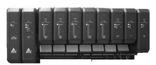
DeltaV is a DCS automation system. DCS is short for Distributed Control System and it
is and automation system that has evolved from PLC.[1]
PLC is short for Programmable Logic Controller. Originally PLC systems replaced old
automation systems that included many relays. PLC systems did then include only
discrete signals and when DCS was new, the difference between the two automation
systems was that DCS also included analog signals. However, today PLC includes both
analog and discrete signals and the difference between PLC and DCS is vague. Newer
designs look similar both in hardware and in software.[2]
The DeltaV automation system consists of one hardware part and one software part. In
the following subsections both parts willl be explained.
1.2.1 Controller, I/O and fieldbus cards
The hardware consists of controller cards, I/O cards and fieldbus cards.
In the controller a CPU is located and it is in the controller that the program containg
information on how to control the process is stored. This program is downloaded to the
controller from a workstation. The I/O cards and the fieldbus cards are capable of
sending or/and receiving signals to and from the devices. Hence, the I/O cards and
fieldbus cards send the signals that they get from the devices to the controller and the
signals that they get from the controller to the devices. The controller also sends
information to an operator interface, so that the operator of the process can monitor it.
Figure 1.2 shows an overview of the connections for an automation system.
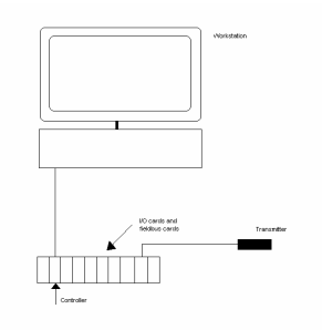
Figure 1.2. Overview of the connections for an automation system. A device is connected to an I/O card
or a fieldbus card. The controller communicates with the I/O cards and the fieldbus cards and is connected
to a workstation. The program is downloaded from a workstation to the controller.
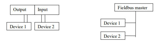
Figure 1.3. The network is reduced when using a fieldbus. Fieldbus cards allow communication in both
directions and the wiring is much less when using fieldbus cards.
In this project three fieldbus cards are used; Foundation Fieldbus, Profibus and ASInterface. Foundation Fieldbus and Profibus handle analogue signals and AS-i only
handles discrete signals.
The communication technology for all three fieldbus cards follows a standard model
-
 Beckhoff C6640-0040 Control Cabinet Industrial PC 7-Slot
 -
 BECKHOFF CONTROL CABINET INDUSTRIAL PC - C6930-1062-0050
 -
 Beckhoff Automation EtherCAT Terminal EK1100 EK1122
 -
 Beckhoff CP6533-0001-0060 IPC
 -
 Beckhoff EK9500 | EtherNet/IP™ Bus Coupler
 -
 Beckhoff CP6202-1047-0050 - An industrial-grade embedded panel computer.
 -
 Beckhoff C6650-0040 Industrial PC
 -
 BECKHOFF CX5230-0185 / 000119805 PLC Module
 -
 BECKHOFF EL4732 | EtherCAT Terminal, 2-channel analog output, voltage, ±10 V, 16 bit, oversampling
 -
 Beckhoff CP6202-0001-0010 Economy Built-In Panel
 -
 Beckhoff AX5206-0000-0202 Digital Compact Servo Drives 2-channel
 -
 Beckhoff CP6606-0001-0020 7-inch Economy Panel PC
 -
 Beckhoff CPU basic module CX2020-0155 + power supply module CX2100-0004
 -
 Beckhoff CP2913-000 Multi-Touch Display
 -
 Beckhoff CP6500-1012-0060 14250369 Control Cabinet
 -
 Beckhoff CP7902-0001-0000 Economy Control Panel with DVI/USB Extended interface
 -
 Beckhoff C6920-0010 Control cabinet Industrial PC
 -
 BECKHOFF C3640-0050 Build-in Industrial PCs
 -
 Beckhoff KL6023-0000 KL6023 EnOcean Wireless-Adapter
 -
 Kollmorgen AKM54G-ANC2DB00 servo motor
 -
 Kollmorgen AKD-P00606-NBCN-0000 Servo Drive
 -
Kollmorgen S200 Series S20350-VTS SERVO DRIVE
-
 KOLLMORGEN AKD-P00606-NBCC-I000 SERVO DRIVE
 -
 Kollmorgen MV65WKS-CE310/22PB Servo Drive Control Module
 -
 Kollmorgen S20360-VTS-021 Servo Drive
 -
 KOLLMORGEN CR06550 High-precision digital servo amplifier
 -
 KOLLMORGEN DBL5N01050-03S-VV0-S40 3-Phase AC Synchronous Brushless Servo Motor
 -
 KOLLMORGEN S70301-NANANA-024 SERVO DRIVE
 -
 Kollmorgen S20360-VTS S200 Series Servo Drive
 -
 Kollmorgen RBE-03011-A00 Brushless Frameless Servo Motor
 -
 KOLLMORGEN AKD-T00306-NBAN-0000 INPUT SERVO DRIVE
 -
 KOLLMORGEN S700 Servo Controller S70302-NANANA
 -
 Kollmorgen AKD-P00607-NBEC-0000 400/480VAC 4.40KVA Servo Drive.
 -
 KOLLMORGEN S70102-NANANA SERVO DRIVE
 -
 KOLLMORGEN AKM21E-ANSNEH02 PM Servo Motor & PRD-AMPE25EB-00 Servo Drive Array
 -
 KollMorgen SC1R06260 Servo Drive 1.4/2.2 KVA 115230 Vac
 -
 Kollmorgen AKD-P00306-NBAN-0000 Servo Drive
 -
Kollmorgen TTB2-2042-3052-A DC Motor Industrial Drive 5.5A 185 oz/in
-
 KOLLMORGEN SERVOSTAR 610-AS SERVO AMPLIFIER_SERVOSTAR610AS_S61001
 -
 KOLLMORGEN PRD-0016400P-10 & PRD-0016600D-30 Axis Control System Modules
 -
KOLLMORGEN Seidel DBL5N01700-03S-000-S40 Servo Motor
-
 Hirschmann RS20-1600M2T1SDAEHH03.1.02 Rail Switch
 -
 Hirschmann BRS30-24TX Industrial Rail Switch
 -
 Hirschmann RSPM20-4T14T1EV9HHS999.9.99 Managed Ethernet Switch
 -
 Hirschmann BELDEN RS40-0009CCCCSDAPHH09.0.14 / RS400009CCCCSDAPHH09014
 -
Hirschmann RS40 Rail Switch RS40-0009CCCCSDAE
-
 Hirschmann BELDEN RS30-0802T1T1SDAP / RS300802T1T1SDAP Fully Managed Layer 2 Compact Rail Switch
 -
 Hirschmann BELDEN RS20-0800M2M2SDAUHH / RS200800M2M2SDAUHH
 -
 Hirschmann EAGLE30-04022O6TT999SCCY9HSE3F Industrial Firewall Router Switch
 -
 Hirschmann RS20-1600T1T1SDAEHH09.0.14 RS20 Rail Mount Ethernet Switch
 -
 Hirschmann EAGLE0200T1T1TDDY90000HHE05.3.03 Industrial Security Router
 -
Hirschmann - BELDEN MIPP-AD-1L9P
-
 HIRSCHMANN RSPM20-4Z64Z6TV9HHS9 942 106-999 RAIL SAFETY SWITCH
 -
 HIRSCHMANN FIBEROPTIC MODULE FIP P/N: OZDFIPG3T
 -
 HIRSCHMANN RS20-1600M2M2SDAUHH Ethernet rack-mounted switch
 -
 HIRSCHMANN BELDEN RS20-0400T1T1SDAEHH04.0.01 / RS200400T1T1SDAEHH04001
 -
HIRSCHMANN MM2-4FXM3 MICE Media Module
-
HIRSCHMANN RS20-0800M2M2SDAE Industrial Ethernet Rail Switch
-
 Hirschmann RS20-2400T1T1SDAP / RS20-2400T1T1SDAPHH05.0.02
 -
 GE MLJ1005B010H00C MLJ Digital Synchromism Check
 -
 ALSTOM MICROTECH DX21-M2 Digital Excitation Controller
 -
HIRSCHMANN BRS20-1200ZZZZ-STCY99HHSES
-
 HIRSCHMANN MM3-4FXM2 MICE Media Module
 -
Hirschmann RSB20-0800T1T1SAABHH 8Port ENet Rail Switch RSB20
-
 Hirschmann MACH102-8TP Ethernet Switch
 -
 SAACKE DDZ-M marine steam pressure atomizer
 -
 SAACKE SKV-A marine rotary cup atomizer
 -
 SAACKE Seavis HMI05e
 -
 Kollmorgen MMC-SD-2.0-230 Servo Drive 100-240VAC 2KW 10A Output 3PH 100-240VAC
 -
 Kollmorgen Servo drive CR10550
 -
 Kollmorgen AKD-P01207-NACN-0054 Servo Driver
 -
 Kollmorgen S406M-CA-036 Servostar
 -
.png) Kollmorgen AKD-B02407-NAAN-0000 Digital Servo Drive
Kollmorgen AKD-B02407-NAAN-0000 Digital Servo Drive -
 Kollmorgen SERVOSTAR S406AM-CA Digital Servo Drive
 -
 KOLLMORGEN SERVOSTAR 603-AS SERVO AMPLIFIER_SERVOSTAR603AS_S60301
 -
Kollmorgen S700 Servo Controller (S70602-NANANA-NA)
-
 Kollmorgen MPK411 controller
 -
 KOLLMORGEN MMC-SD-1.3-460-D Smart Drive
 -
 KOLLMORGEN AKM21C-CKB2AA-00 / AKM21CCKB2AA00 Servomotor
 -
 BECKHOFF AX5106-0000-0200 | Digital Compact Servo Drives 1-channel
 -
 BECKHOFF C3620-0000 INDUSTRIAL COMPUTER (MOTORSHELVES)
 -
 Beckhoff EK1960-0000 TwinSAFE Compact Controller
 -
 Beckhoff C6930-0050 Control Cabinet Industrial PC
 -
 Beckhoff CP7711-0001-0030 Industrial Computer Detection
 -
 Beckhoff CX1001-0111 Embedded PC CPU Module
 -
 Beckhoff C6017-0020 | Ultra-compact Industrial PC
 -
 Beckhoff EK1322 | 2-port EtherCAT P junction with feed-in
 -
 Beckhoff CP2219-0010 Panel
 -
 BECKHOFF C6015-0020 ULTRA COMPACT INDUSTRIAL PC
 -
 BECKHOFF CX2030-0120/Standard CPU Module Embedded PC Windows PLC controller
 -
 Beckhoff CP7721-1090-0020 Panel PC
 -
 Beckhoff PC CPU Module CX5130-0175
 -
 Beckhoff C6920-0050 Control Cabinet
 -
 Beckhoff EL6631 EtherCAT 2-Port Communication Interface, Profinet RT Controller
 -
 Beckhoff CP6202-0001-0060 touch screen panel PC
 -
 Beckhoff CP3916-1002-0000 Multi-Touch Control Panel
 -
 Beckhoff EP1809-0021 | EtherCAT Box, 16-channel digital input, 24 V DC, 3 ms, M8Preferred type
 -
 Beckhoff CX8190 PLC Embedded Industrial PC Ethernet Controller
 -
 Beckhoff CX2100-0914 Power Supply for External
 -
 Beckhoff Automation CP6906-0001-0000 HMI
 -
 Beckhoff EP7342-0002 Module
 -
 Beckhoff CX1020-0112 / CX1100-0910 / CX1020-N010 / CX1100-0003 Windows CPU
 -
 Beckhoff EP7211-0034 EtherCAT Box 1 Channel Motion Interface
 -
 Beckhoff C6240-0030 Control cabinet Industrial PC
 -
 beckhoff motherboard CB1052-0004 CB1052-0004
 -
 Beckhoff AX2006-AS Servo Drive / Variable Frequency Drive
 -
BECKHOFF CP6207-0001-0020 NSMP
-
 Beckhoff C6930-1142-0060 Industrial Computer
 -
 Beckhoff FC7501-0000 interface card
 -
 Beckhoff CX5140-0175 Embedded PC PLC CPU CX5140 Industrial Controller
 -
 Beckhoff CP7802-1100-0010: High-End IP65 Control Panel with DVI/USB Extended Interface
 -
BECKHOFF CP3716-1058-0010 CONTROL PANEL
-
 Beckhoff AX8108-0000 Single-Axis Module
 -
 Beckhoff CU8851-0000 | USB extension, USB Extended 2.0 receiver box
 -
Beckhoff C6017-0030 | Ultra-compact Industrial PC
-
 Beckhoff CX1001-0120/CX10010120.cx1000-n001.cx1000-n000 System Overview
 -
 Beckhoff CPU Module CX5140-0155/4GB CPU Module
 -
 Beckhoff CP6533-0001-005: Built-in Panel PC with High-Definition Multi-Touch Control
 -
 Beckhoff EL5042 | EtherCAT Terminal, 2-channel encoder interface, BiSS® C
 -
 Beckhoff C6920-1080-0040: Premium Control Cabinet Industrial PC
 -
 Beckhoff C6920-0060 | Control cabinet Industrial PC
 -
 Beckhoff Embedded-PC CX5010-1121
 -
 Beckhoff CB3050-0010 Mainboard Motherboard
 -
 Beckhoff PLC module CX1020-0000 Basic CPU module (service phase)
 -
 Beckhoff CP7812-1056-0010 15" Multitouch Display Control Panel
 -
 Beckhoff CX5120-0115 /2GB Controller Module
 -
 Beckhoff CP7201-1000-0000 Industrial Panel PC
 -
 Beckhoff Servo Motor AM8061-0JH1-0000


