
EMERSONMVME55006E Single-Board Computer Installation and Use
ESD
Emerson strongly recommends that you use an antistatic wrist strap and a
conductive foam pad when installing or upgrading a system. Electronic components,
such as disk drives, computer boards, and memory modules can be extremely
sensitive to electrostatic discharge (ESD). After removing the component from its
protective wrapper or from the system, place the component flat on a grounded,
static-free surface (and, in the case of a board, component side up). Do not slide the
component over any surface.
If an ESD station is not available, you can avoid damage resulting from ESD by
wearing an antistatic wrist strap (available at electronics stores) that is attached to an
active electrical ground. Note that a system chassis may not be grounded if it is
unplugged.
Personal Injury or Death
Dangerous voltages, capable of causing death, are present in this equipment.
Use extreme caution when handling, testing, and adjusting.
Configuring the Hardware
This section discusses certain hardware and software tasks that may need to be performed
prior to installing the board in a chassis.
To produce the desired configuration and ensure proper operation of the MVME5500, you may
need to carry out certain hardware modifications before installing the module.
Most options on the MVME5500 are software configurable. Configuration changes are made
by setting bits in control registers after the board is installed in a system.
Jumpers and switches are used to control those options that are not software configurable.
These settings are described further on in this section. If you are resetting the board jumpers
or switches from their default settings, it is important to verify that all settings are reset properly.
Configuring the Board
Figure 1-1 illustrates the placement of the jumpers, headers, switches, connectors, and various
other components on the MVME5500. There are several manually configurable headers and
switches on the MVME5500 and their settings are shown in Table 1-2. Each default setting is
enclosed in brackets. For pin assignments on the MVME5500, refer to Chapter 5, Connector
Pin Assignments.
Table 1-2 MVME5500 Jumper Settings

The MVME5500 is factory tested and shipped with the configuration described in the following
section.
1.6.2 Ethernet 2, PMC/SBC Mode, and P2 I/O Selection Headers (J6,
J7, J28, J32, J34, J97 – J110)
All of the headers described below are used in conjunction with each other to select various
modes of operation for 10/100BaseT Ethernet, PMC/SBC mode, and P2 I/O mode.
1.6.2.1 Ethernet
Four 3-pin planar headers (J6, J7, J100, J101) and four 2-pin planar headers (J34, J97, J98,
J99) are for 10/100/BaseT Ethernet 2 selection.
Ethernet 1 is the Gigabit Ethernet port and is front panel only.
Figure 1-1 MVME5500 Board Layout
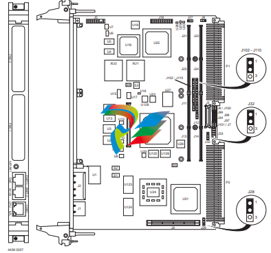
For J6, J100, J7 and J101, install jumpers across pins 2-3 on all four headers for rear P2
Ethernet. For front-panel Ethernet, install jumpers across pins 1-2 on all four headers.
For J34, J97, J98 and J99, no jumpers are installed for front-panel Ethernet. For rear P2
Ethernet, install jumpers across pins 1-2 on all four headers when in SBC/IPMC761 mode.
1.6.2.2 PMC/SBC Mode Selection
The MVME5500 is set at the factory for PMC mode. The SBC/IPMC761 mode should only be
selected when using the IPMC761 module in conjunction with the MVME761 transition
module.The PMC mode should be selected when using PMC modules with specific user I/O in
conjunction with the corresponding transition module. PMC mode should also be selected when
using PrPMC modules.
Two 3-pin planar headers (J28, J32) control the supply of +/- 12 volts to the P2 connector; one
or both of these voltages are required by the MVME712 or MVME761 module when operating
in SBC mode. For PMC mode, jumpers are installed across pins 1-2 on both headers. For
SBC/IPMC761 mode, install jumpers across pins 2-3 on both headers. For SBC/IPMC712
mode, install a jumper across pins 2-3 for J32 and install a jumper across pins 1-2 for J28
Product Damage
When J28 is configured for SBC/IPMC mode, –12V is supplied to P2 pin A30. If there
is an incompatible board plugged into this P2 slot, damage may occur.
When J32 is configured for SBC/IPMC mode, +12V is supplied to P2 pin C7. If there is
an incompatible board plugged into this P2 slot, damage may occur.
P2 I/O Selection
Nine 3-pin planar headers (J102 –J110) are for P2 I/O selection. Jumpers are installed across
pins 1-2 on all nine headers when in PMC mode. Install jumpers across pins 2-3 on all nine
headers when in SBC/IPMC761 or SBC/IPMC712 mode to connect the extended SCSI signals
to P2
Flash Boot Bank Select Header (J8)
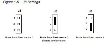
A 3-pin planar header selects the boot Flash bank. No jumper or a jumper installed across pins
1-2 selects Flash 0 as the boot bank. A jumper installed across pins 2-3 selects Flash 1 as the
boot bank.
Flash 0 Programming Enable Switch (S3-1)
This switch enables/disables programming of Flash 0 as a means of protecting the contents
-
 CTI 2500-ADP2-DISC Discrete Wiring Adapter for Series 500
 -
 CTI 2500-ADP1 Analog Wiring Adapter for Series 500
 -
 CTI 2500C-RADP-RS485 Remote Base Controller Adapter for Series 500
 -
 CTI 2500C-RADP-RBC Profibus RBC Adapter for Series 500
 -
 CTI 2500C-PADP-120V 120VAC 50W Power Supply for Series 500
 -
 CTI 2500-RADP RBC Adapter for Series 500
 -
 CTI 2500-R4500 520/530/DBC Adapter for Series 500 - MATURE
 -
 CTI 2500-PADP Power Supply Adapter for Series 500
 -
 CTI 2500-IADP I/O Adapter for Series 500
 -
 CTI 2500-VP15A-N4-W7 15" Flat-Panel PC with Windows® 7 Embedded
 -
 CTI 2500S-27-1750 Slice I/O, Ethernet, RS232/485. 900MHz, 2DIO / 4UAI / 2AI
 -
 CTI 2500S-26-1750 Slice I/O, Ethernet, RS232/485. 900MHz, 8DIO / 2UAI
 -
 CTI 2500S-23-1750 Slice I/O, Ethernet, RS232/485. 900MHz, 4DI / 4DO / 2UAI / 2AO
 -
 CTI 2500S-27-1550 Slice I/O, RS232/485. 2DIO / 4UAI / 2AI
 -
 CTI 2500S-26-1550 Slice I/O, RS232/485. 8DIO / 2UAI
 -
 CTI 2500S-23-1550 Slice I/O, RS232/485. 4DI / 4DO / 2UAI / 2AO
 -
 CTI 2500S-27-1050 Slice I/O, Ethernet, 2DIO / 4UAI / 2AI
 -
 CTI 2500S-26-1050 Slice I/O, Ethernet, 8DIO / 2UAI
 -
 CTI 2500S-23-1050 Slice I/O, Ethernet, 4DI / 4DO / 2UAI / 2AO
 -
 CTI 2500C-32F-CJC 32-Pin Field Wiring Connector with Cold Junction Compensation
 -
 CTI 2500C-32F 32-Pin Field Wiring Connector
 -
 CTI 2500C-8-TC Eight Thermocouple Inputs
 -
 CTI 2500C-8-RTD Eight RTD Inputs
 -
 CTI 2500C-8-RL-FC 8 Form-C Relay Outputs
 -
 CTI 2500C-8-IDO-24V 8 Isolated 24VDC Outputs
 -
 CTI 2500C-8-IDO-120V 8 Isolated 120VAC Outputs
 -
 CTI 2500C-16-DO-24V Sixteen 24VDC Digital Outputs
 -
 CTI 2500C-16-DO-120V Sixteen 120VAC Digital Outputs
 -
.png) CTI 500C-16-IDI-24V Sixteen Isolated 24V AC/DC Digital Inputs
CTI 500C-16-IDI-24V Sixteen Isolated 24V AC/DC Digital Inputs -
 CTI 2500C-16-IDI-120V Sixteen Isolated 120V AC/DC Digital Inputs
 -
 CTI 2500C-16-DIDO-SIM Sixteen Digital Input and Output SImulator
 -
 CTI 2500C-16-DI-24V Sixteen 24V AC/DC Digital Inputs
 -
 CTI 2500C-16-DI-120V Sixteen 120V AC/DC Digital Inputs
 -
 CTI 2500C-RBC-RS485 RS485 Remote Base Controller
 -
 CTI 2500C-RBC-PRF Profibus Remote Base Controller
 -
 CTI 2500C-PS-24V-35 35-Watt DC Power Supply
 -
 CTI 2500C-PS-120V-35 35-Watt AC Power Supply
 -
 CTI 2500C-R8 Eight-Slot Base
 -
 CTI 2500C-R4 Four-Slot Base
 -
 CTI 2500C-R16 Sixteen-Slot Base
 -
 CTI 2500C-2572-B Fast Ethernet TCP/IP Adapter
 -
 CTI 2500C-J750 Compact Janus PAC with 3MB Project Memory
 -
 CTI 2500C-C300 CPU with 512K User Memory
 -
 CTI 2500C-C200 CPU with 256K User Memory
 -
 CTI 2500C-C100 CPU with 128K User Memory
 -
 CTI 2500C-8-AO 8 Analog Outputs
 -
 CTI 2500C-8-AI 8 Analog Inputs
 -
 CTI 2559-FCAL Precision Calibration Connector
 -
 CTI 2559-FPC 40-Position Screw-Terminal Connector
 -
 CTI 2500-RFC PLC to RF Modem Cable
 -
 CTI 2500-40F 40-Position Standard Screw-Terminal Connector
 -
 CTI 2505 Vibration Sensor Interface Module
 -
 CTI 2554-A 4-Channel Isolated High Speed Counter Module
 -
 CTI 2553-A 2-Channel Mag Meter Input Module
 -
 CTI 2502 2-Channel High Speed Counter Input Module
 -
 CTI 2559-TC 8-Channel Thermocouple Input Module
 -
 CTI 2556-A 16-Channel Isolated Thermocouple Input Module
 -
 CTI 2556 16-Channel Isolated Thermocouple Input Module
 -
 CTI 2551-A 8-Channel Isolated Thermocouple Input Module
 -
 CTI 2559-RTD 8-Channel RTD Input Module
 -
 CTI 2557-A 16-Channel RTD Input Module
 -
 CTI 2557 16-Channel RTD Input Module
 -
 CTI 2552-A 8-Channel Isolated RTD Input Module
 -
 CTI 2534 8-Point Form-C Relay Output Module
 -
 CTI 2532 16-Point Form-A Relay Output Module
 -
 CTI 2531 32-Point Form-A Relay Output Module
 -
 CTI 2530 8-Point Form-C Relay Output Module
 -
 CTI 2562 8-Channel Analog Output Module
 -
 CTI 2560-A 8-Channel Isolated Analog Output Module
 -
 CTI 2501 8in/4out Analog Module
 -
 CTI 2558 8-Channel Analog Input Module
 -
 CTI 2555-A 16-Channel Analog Input Module
 -
 CTI 2550-A 8-Channel Isolated Analog Input Module
 -
 CTI 2599 8/16/32-Point AC Output Module
 -
 CTI 2598-8 8-Point AC Output Module
 -
 CTI 2598 8/16-Point AC Output Module
 -
 CTI 2597 8/16/32-Point DC Output Module
 -
 CTI 2596-8 8-Point DC Output Module
 -
 CTI 2596 8/16-Point DC Output Module
 -
 CTI 2595 16-Point TTL/Word Output Module
 -
 CTI 2591-EF 16-Point Isolated 11-146 VDC Output with Front Panel Accessible Fuses
 -
 CTI 2591-A 16-Point Isolated 11-146 VDC Output Module
 -
 CTI 2590-EF 16-Point Isolated 20-132 VAC Output with Front Panel Accessible Fuses
 -
 CTI 2590-A 16-Point Isolated Discrete 20-132 VAC Output Module
 -
 CTI 2589-B 8/16/32-Point Universal Discrete Input Module
 -
 CTI 2589-A 8/16/32-Point Universal Discrete Input Module
 -
 CTI 2588-8 8-Point Universal Discrete Input Module
 -
 CTI 2585 16-Point TTL/Word Input Module
 -
 CTI 2582 16-Point Isolated 125 VDC Input Module
 -
 CTI 2581 16-Point Isolated 12-56 VDC Input Module
 -
 CTI 2580 16-Point Isolated 95-132 VAC Input Module
 -
 CTI 2500-TAP RS485 Network Tap
 -
 CTI 2500-RIO-B RS485 Remote Base Controller
 -
 CTI 2500-RIO-A RS485 Remote Base Controller
 -
 CTI 2500-RBC Profibus Remote Base Controller
 -
 CTI 2515-A 100-Watt AC/DC Power Supply with Redundancy Support
 -
 CTI 2515 100-Watt AC Power Supply (MATURE - replaced by 2515-A)
 -
 CTI 2513-A 75-Watt DC Power Supply with Redundancy Support
 -
 CTI 2513 75-Watt 24VDC Power Supply
 -
 CTI 2512-A 75-Watt AC/DC Power Supply with Redundancy Support
 -
 CTI 2512 75-Watt AC/DC Power Supply
 -
 CTI 2510 125 VDC Power Supply
 -
 CTI 2500-SSB Single Slot Blank Front Panel
 -
 CTI 2500-R11-A Eleven-Slot Redundant Base
 -
 CTI 2500P-R16 Sixteen-Slot Base with High-Speed Channel
 -
 CTI 2500P-R8 Eight-Slot Base with High-Speed Channel
 -
 CTI 2500P-R4 Four-Slot Base with High-Speed Channel
 -
 CTI 2541 Redundant Processor Manager Module
 -
 CTI 2577 Profibus DP Slave Adapter
 -
 CTI 2573-MOD Serial Interface Adapter with MODBUS
 -
 CTI 2572-AF Fast Ethernet TCP/IP Adapter with Optical Fiber Connection
 -
 CTI 2572-A Fast Ethernet TCP/IP Adapter
 -
 CTI 2572 Ethernet TCP/IP Adapter
 -
 CTI 2572-B Fast Ethernet TCP/IP Adapter
 -
 CTI 2576 DeviceNet™ Scanner Module (MATURE)
 -
 CTI 2500P-ECC1 Ethernet Communications Coprocessor
 -
 CTI 2500P-JACP Janus Application Coprocessor
 -
 CTI 2500P-ACP1 Application Coprocessor (MATURE - replaced by 2500P-JACP)
 -
 CTI 2500P-J450 Janus PAC with 2MB Project Memory
 -
 CTI 2500-C400 CPU with 3072K User Memory
 -
 CTI 2500-C300 CPU with 512K User Memory
 -
 CTI 2500-C200 CPU with 256K User Memory
 -
 CTI 2500-C100 CPU with 128K User Memory
 -
 CTI 2500P-J750 Janus PAC with 3MB Project Memory
 -
 Shinkawa WHF3006M Displacement Converter
 -
Shinkawa JBP-220 (P-24-94A / P-24-94B) Circuit Board Module
-
 SHINKAWA WKN-142K5 2-WIRE VIBRATION TRANSDUCER
 -
Shinkawa FRP-321 (P-26-54A / P-26-54B) Circuit Board Module


