
Understanding Loop Diagrams and Process Loop Sheets
Because the design engineer has likely not looked at these signals together (i.e., there was no corresponding loop diagram to be subjected to QA/QC), often there will be minor I/O errors in the design. The electrician will need to resolve the errors on-site or issue a request for information (RFI) to the design team to obtain the necessary data. All of this is very time-consuming during the construction phase, and the contractors are under tremendous pressure to get the plant built.
Likewise, suppose an installed valve actuator requires troubleshooting. In an ideal situation, an as-built loop diagram or process loop sheet for the actuator will include all the information the maintenance electrician will need to check the power and signals to/from the actuator. (When a construction project is completed, the design engineer will prepare an updated set of the contract drawings called “as-built” or “for record” that captures the details of what was actually built verses the initial plans.) However, suppose there is no loop diagram for the actuator. The electrician will have to search through PLC panel drawings, other drawings and equipment manuals to determine how the actuator is wired and powered.
Often, if there are no loop diagrams, no drawing will exist that shows how the terminal screws of the valve actuator have been wired and what the terminals and configuration do. Thus, without a loop diagram, a simple 10-minute troubleshooting task can turn into hours of difficult trial-and-error troubleshooting to find the issue.
Process loop sheets may be drawn by hand or produced in a drawing application such as AutoCAD (see Figure 3). On small projects, the sheets can easily be attached to the contract specification documents or placed with the engineering specifications to create an efficient and manageable document.
A process loop sheet is typically divided into as many horizontal layers—from the bottom of the drawing to the top—as required to show the entire loop diagram from the field device (at the bottom) to the control room (at the top). The following paragraphs provide an overview of the example Process Loop Sheet shown in Figure 4.
The top layer, just below the equipment description blocks, is the control room or administrative office at the end of the loop. The field device is always located in the bottom layer with intermediate layers denoting the path between the device and the control room, such as local control panels, remote I/O cabinets, PLC or DCS panels, or a fiber optic communication system. Each device and piece of equipment is assigned a unique ID to indicate that it is in a specific instrument loop. Best practice is to use the ISA-5.1 standards for assignment instrument IDs. However some SCADA systems may use different labeling systems, so these labels should also included if applicable.
The process loop sheet example in Figure 4 contains additional installation, commissioning and troubleshooting information. The following paragraphs provide an explanation of the various pieces of information contained on this process loop sheet example.
Data fields. The process loop sheet contains fields where the designer can enter data. Each field contains a key piece of information about the device, instrument, or equipment connected to the control system. The loop name and number fields are located at the bottom of the sheet. The fields at the top of the form are referred to as description blocks. These blocks include detailed information about all the instruments and components in the loop diagram. A separate row is created for each instrument or device in the loop.
Loop name. This is a brief description of the process being monitored or controlled.
Loop number. This is a unique, four-digit number identifying the instrument loop.
Item. This is a unique, four-digit alpha identifier for each piece of field equipment in the loop. These identifiers, called instrument codes, are defined in the ISA-5.1 standard for instrumentation. Identifiers for other devices will be typically defined in an end-user-specific standard. It is important to note that there are many of the same types of instruments. That is why each device and piece of equipment should be assigned a unique ID that is only used once at the plant. For example, ISA-5.1 provides a method of doing this using loop numbers, but each plant may have its own internal convention. The important takeaway is that the identifier must be unique.
Description. This area explains the identifiers in the Item block. This block is valuable to anyone unfamiliar with ISA standard terminology and/or the plant’s instrument/ device tagging system.
Type. This block provides details about each device. For example, it may identify a flow element (FE) as either a magnetic flow meter, a Venturi flow tube, or an ultrasonic flow meter.
Criteria. This block contains requirements that are unique to the device or piece of equipment, such as the color of a pilot light lens, calibrated pressure, temperature, low-flow range requirements, elevations of level switches and analysis analyzer ranges. This block or the Type block may also contain information indicating which contractor is responsible for providing the device or piece of equipment. If there are special installation or commissioning requirements that are unique to a particular instrument, these will sometimes be also included on the process loop sheet.
Tag/service. This block is used to identify the item and what it does in the process. This is useful for an individual who does not understand the process or plant requirements, as well as someone assembling a control panel who must identify each piece of equipment on the panel by the process that is either being controlled or monitored.
Quantity. This is the number of items.For example, if multiple items of the same type are needed a quantity is listed rather than having multiple row entries. Likewise if similar, but slightly different, items are needed it is best to list them separately in separate rows.
-
 GE SR745-W2-P1-G1-HI-A-L-R-E Feeder protection relay
 -
 GE IS230TNDSH2A Discrete Output Relay Module Brand
 -
 GE Fanuc IS200TDBSH2ACC Mark VI Terminal Board Brand
 -
 GE PMC-0247RC-282000 350-93750247-282000F Disk Drive
 -
GE PMC-0247RC-282000 350-93750247-282000F Disk Drive
-
 GE VMIVME-1150 Serial Communications Controller
 -
 GE VMIVME-5576 Fiber-Optic Reflective Memory with Interrupts
 -
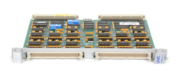
 GE VMIC Isolated Digital Output VMIVME-2170A
 -
 GE MULTILIN 760 FEEDER MANAGEMENT RELAY 760-P5-G5-S5-HI-A20-R-E
 -
 GE IS200AEPAH1BKE IS215WEPAH2BB Printed circuit board
 -
 GE IS210BPPCH1A Mark VIe I/O Pack Processor Card
 -
 GE IS220PRTDH1A 336A4940CSP6 High-Performance RTD Input Module
 -
GE IS220PDIAH1BE 336A5026ADP4 Discrete Input Module
-
 GE IS420ESWBH3A IONET Switch Module
 -
 GE 516TX 336A4940DNP516TX 16-port Ethernet switch
 -
 GE EVMECNTM13 Embedded control module
 -
 GE EVPBDP0001 EVPBDP032 control module
 -
 GE Hydran M2-X Enhanced Monitoring with Extended Sensor Life
 -
 GE UR6CH Digital I/O Module
 -
 GE IC695CPU315-CD Central processing unit
 -
 GE 531X305NTBAMG1 DR Terminal Board
 -
 GE 531X305NTBALG1 NTB/3TB Terminal Board 531X Series
 -
 GE 531X305NTBAJG1 NTB/3TB Terminal Board.
 -
 GE 531X305NTBAHG1 NTB/3TB Terminal Board 531X
 -
 GE 531X305NTBAEG1 is a PCB that functions as a DR terminal board.
 -
General Electric 531X305NTBACG1 NTB/3TB Terminal Board 531X
-
 GE Digital Energy D20 Analog Input Module
 -
 GE 94-164136-001 main board Control board
 -
 GE 269 PLUS-D/O-100P-125V Digital motor relay
 -
 GALIL DMC-9940 High-performance motion controller
 -
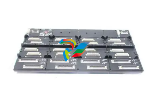
 FUJI NP1BS-08 base plate
 -
 FUJI NP1Y32T09P1 Transistor drain type digital output module
 -
 FUJI NP1Y16R-08 Digital Output Module
 -
 FUJI NP1X3206-A High-speed digital input module
 -
 FUJI NP1AYH4I-MR current output module
 -
 FUJI NP1S-22 Power module redundancy
 -
 FUJI RPXD2150-1T servo drive module
 -
 FUJI FVR008E7S-2UX Ac frequency converter
 -
 FUJI Ac frequency converter FVR008E7S-2
 -
 FUJI FVR004G5B-2 Small general-purpose frequency converter
 -
 FUJI A50L-2001-0232 Industrial control module
 -
 FUJI A50L-001-0266#N High-performance servo amplifier
 -
 Honeywell FS7-2173-2RP Gas sensor
 -
 Honeywell 10106/2/1 Digital Input Module in Stock
 -
 FRCE SYS68K CPU-40 B/16 PLC core processor module
 -
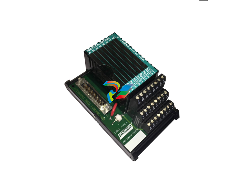
 Foxboro FBM I/O cards PBCO-D8-009
 -
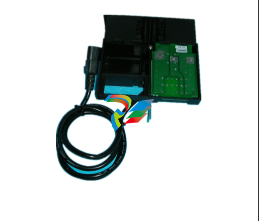
 Foxboro AD916AE Digital Control System (DCS) Module
 -
 GE SR750-P5-G5-S5-HI-A20-R-E Multilin Relay
 -
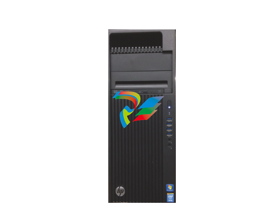
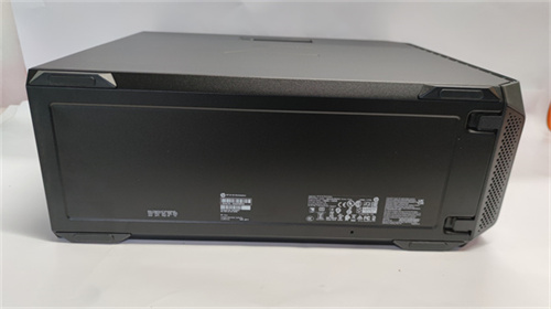
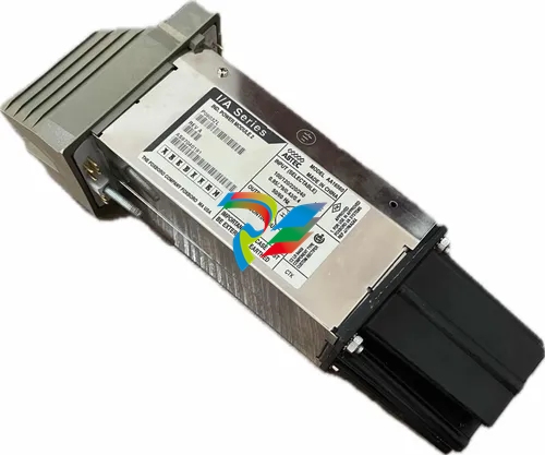
.jpg) FOXBORO H90 H90C9AA0117S Industrial Computer Workstation
FOXBORO H90 H90C9AA0117S Industrial Computer Workstation -
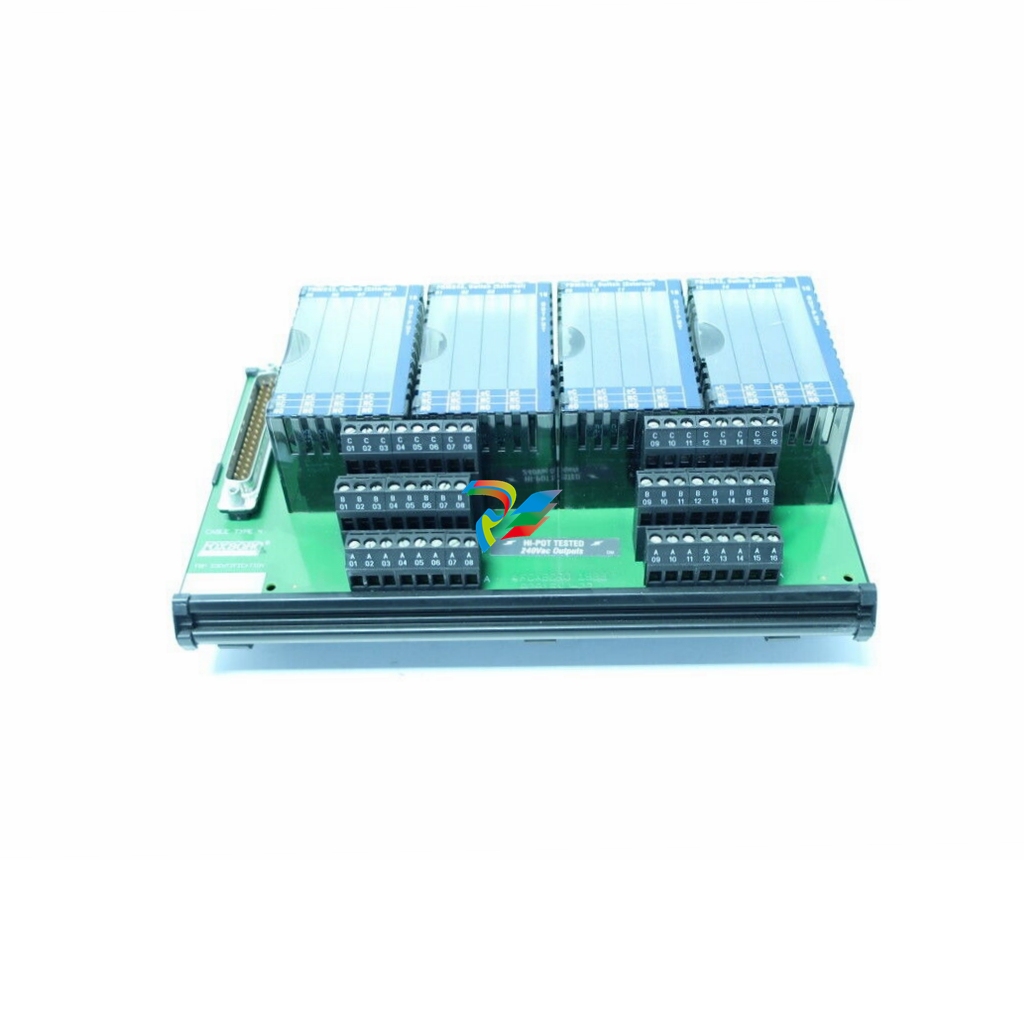
.jpg) FOXBORO RH928AW | I/A Series Relay Output Module
FOXBORO RH928AW | I/A Series Relay Output Module -
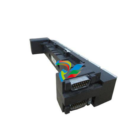
.jpg) Foxboro N-2AX+DIO Multi-functional input/output module
Foxboro N-2AX+DIO Multi-functional input/output module -
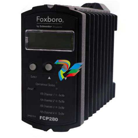 Foxboro RH924WA FCP280 Fiber Optic Network Adapter
 -
 FOXBORO H92 Versatile Hardware Component In
 -
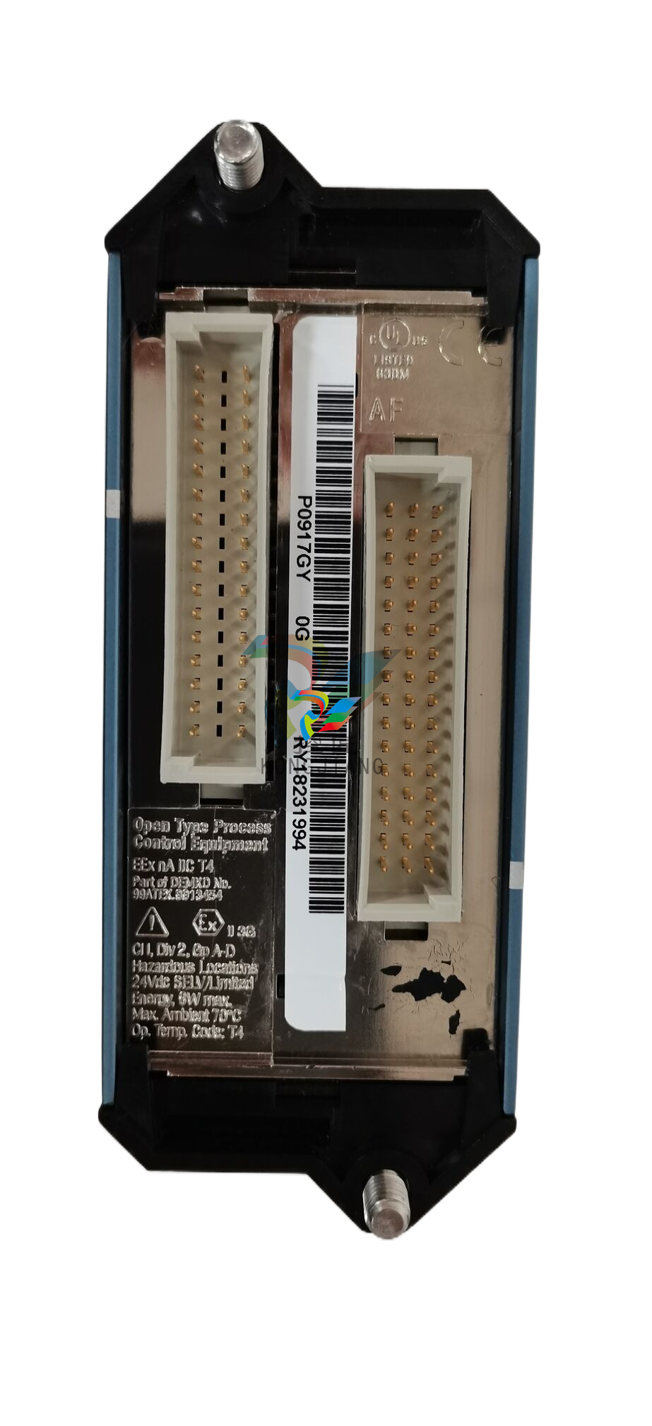
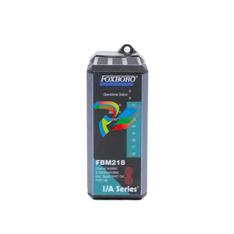 Foxboro FBM218 P0922VW HART® Communication Redundant Output Interface Module
 -
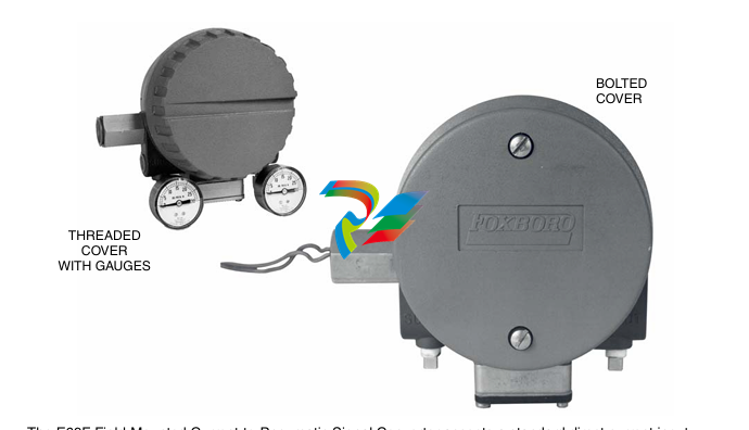
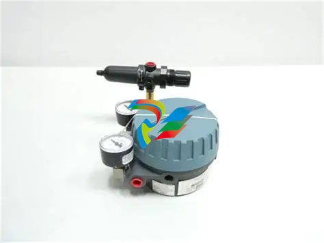
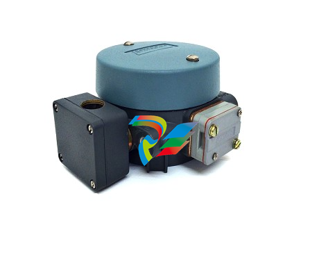 Foxboro E69F-TI2-J-R-S E69F Series Current-To-Pneumatic Signal Converter
 -
 Foxboro E69F-BI2-S Converter
 -
.jpg) Foxboro H92A049E0700 The host of the DCS control station
Foxboro H92A049E0700 The host of the DCS control station -
 Foxboro H90C9AA0117S Industrial computer workstation
 -
 Foxboro RH101AA High-performance industrial control module
 -
 Foxboro P0922YU FPS400-24 I/A Series Power supply
 -
.png) FOXBORO P0973LN Chassis-based managed switch with independent power supply
FOXBORO P0973LN Chassis-based managed switch with independent power supply -
.jpg) FOXBORO P0926PA Input/output module
FOXBORO P0926PA Input/output module -
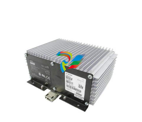
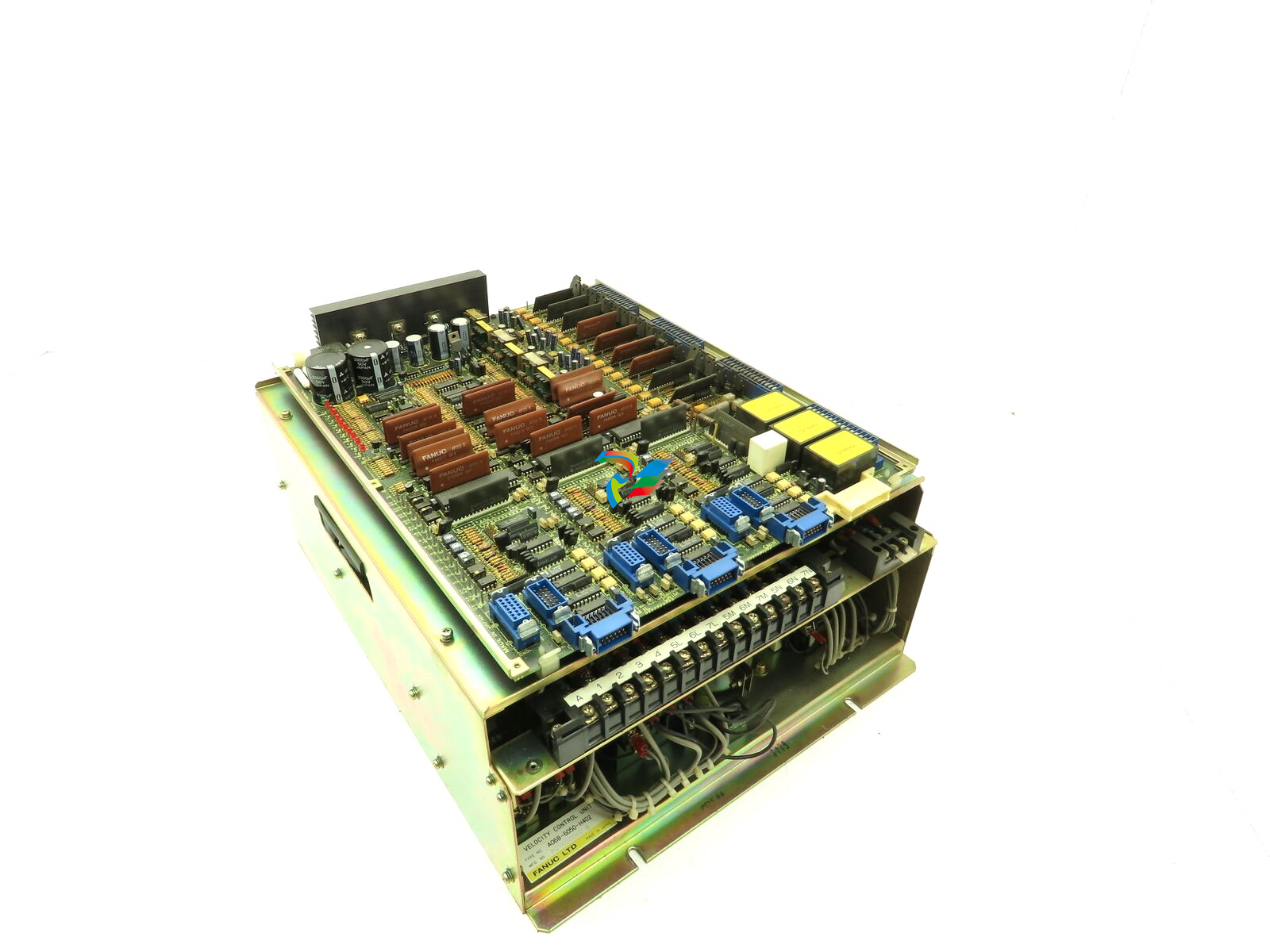 Fanuc A06B-6050-H402 3 AXIS ANALOG AC SERVO DRIVE
 -
.jpg) FOXBORO L0130AD L0130AE-0H Power module group
FOXBORO L0130AD L0130AE-0H Power module group -
_lVjBYb.jpg) FOXBORO 0399085B 0303440C+0303458A Combination Control Module
FOXBORO 0399085B 0303440C+0303458A Combination Control Module -
 FOXBORO SY-0399095E (SY-0303451D+SY-0303460E) Process control board
 -
.jpg) FOXBORO 0399071D 0303440C+0303443B Input/Output (I/O) Module
FOXBORO 0399071D 0303440C+0303443B Input/Output (I/O) Module -
.jpg) FOXBORO RH924UQ Redundant Controller module
FOXBORO RH924UQ Redundant Controller module -
 FFOXBORO E69F-TI2-S current pneumatic converter
 -
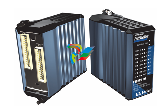 FOXBORO FBM219 RH916RH Discrete I/O Module
 -
 FOXBORO FBM227 P0927AC Module
 -
.jpg) FOXBORO 0399144 SY-0301059F SY-1025115C/SY-1025120E I/O module
FOXBORO 0399144 SY-0301059F SY-1025115C/SY-1025120E I/O module -
.jpg) FOXBORO SY-60399001R SY-60301001RB Industrial Control Module
FOXBORO SY-60399001R SY-60301001RB Industrial Control Module -
 FOXBORO 0399143 SY-0301060R SY-1025115C SY-1025120E Combined control board
 -
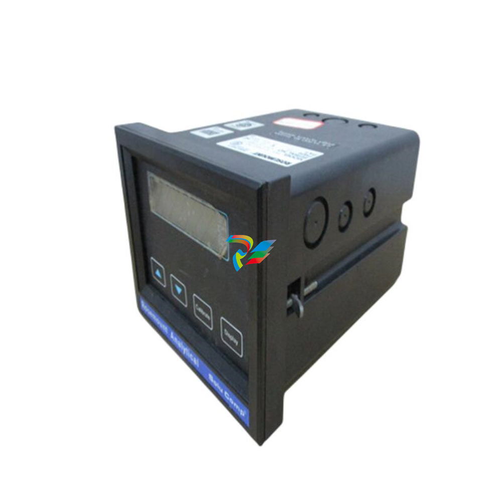
 FOXBORO 873EC-JIPFGZ electrodeless conductivity analyzer
 -
 FOXBORO P0916PH (High-density HART I/O Module)
 -
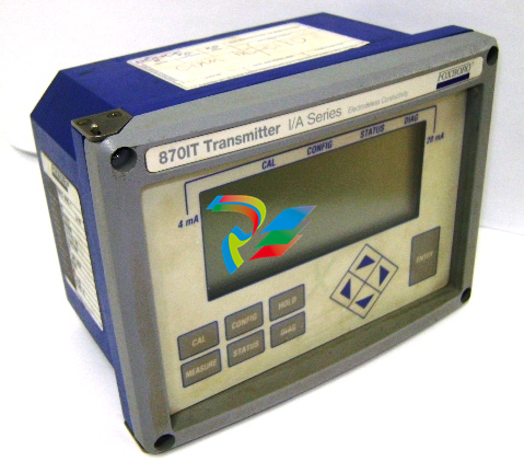 FOXBORO 870ITEC-AYFNZ-7 Intelligent Electrochemical Transmitters
 -
 FOXBORO Compact FBM240. Redundant with Readback, Discrete
 -
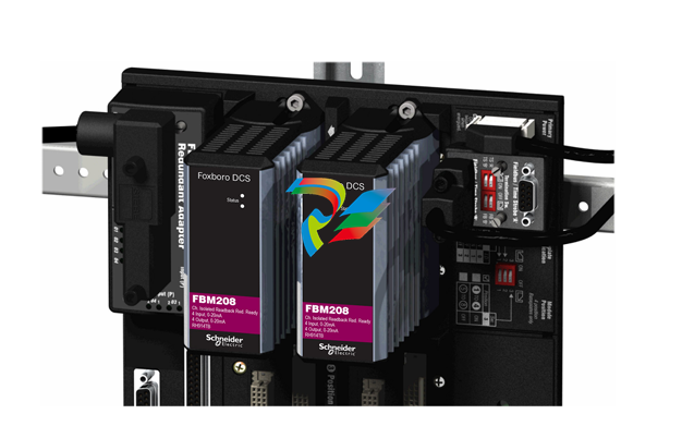 FOXBORO FBM208/b, Redundant with Readback, 0 to 20 mA I/O Module
 -
 FOXBORO FBM201e Analog Input (0 to 20 mA) Interface Modules
 -
.jpg) FOXBORO P0916WG Terminal cable
FOXBORO P0916WG Terminal cable -
 FOXBORO P0926MX 2-Port Splitter
 -
.jpg) FOXBORO AD908JQ High-Frequency Module
FOXBORO AD908JQ High-Frequency Module -
.jpg) FOXBORO AD916CC Processor module
FOXBORO AD916CC Processor module -
 Foxboro DCS FBM206 Pulse Input Module
 -
 FOXBORO FBM216 HART® Communication Redundant Input Interface Module
 -
 Foxboro p0903nu 1×8 unit sub-component module
 -
 Foxboro P0911SM Industrial control module
 -
 Foxboro CM902WM I/O module
 -
 Foxboro CM902WL Power module
 -
 Foxboro P0972VA Industrial Control Module
 -
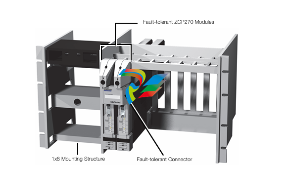
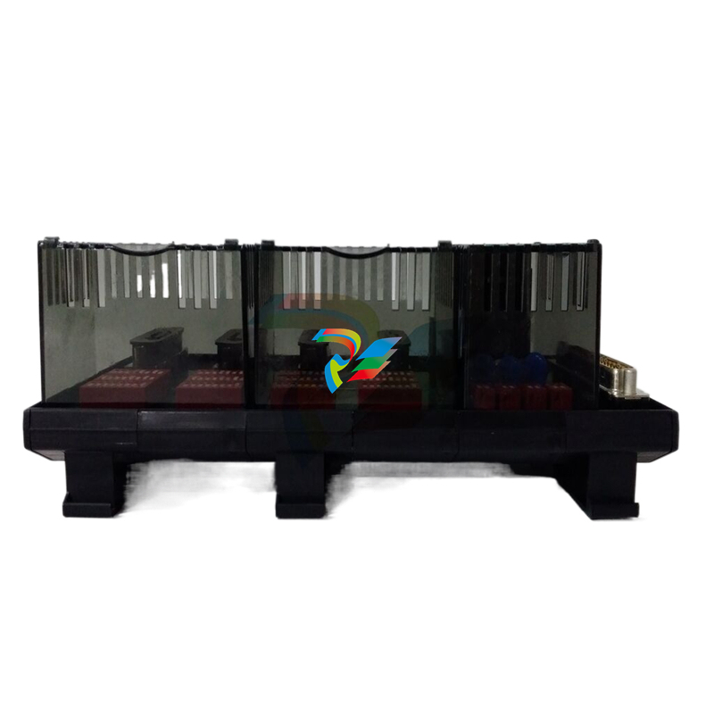
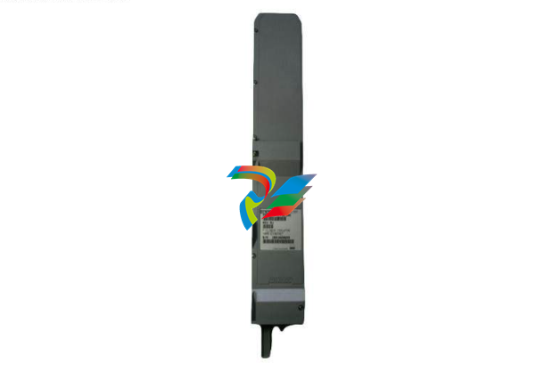
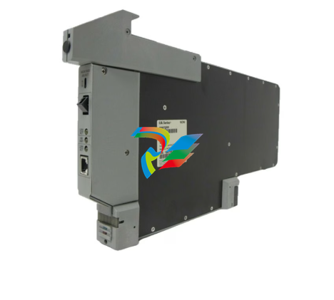
 Foxboro Z-Module Control Processor 270 (ZCP270)
 -
 Foxboro PO916JS 16-channel terminal block module
 -
 Foxboro PO911SM High-performance digital/analog input/output module
 -
 Foxboro P0972PP-NCNI Network Interface Module
 -
.jpg) FOXBORO P0971QZ controller module
FOXBORO P0971QZ controller module -
 FOXBORO P0971DP Thermal resistance input/output module
 -
 FOXBORO P0970VB Cable connector
 -
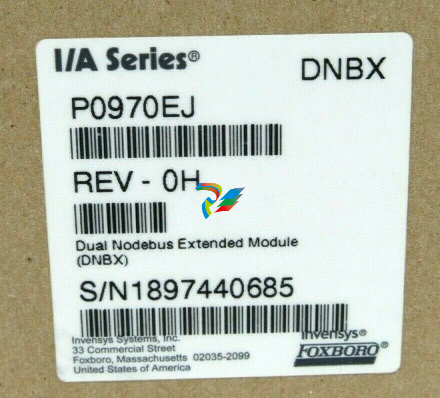 FOXBORO P0970EJ-DNBX Dual-node bus expansion module
 -
 FOXBORO P0970BP Redundant power supply system
 -
.jpg) FOXBORO P0970BC-DNBI DeviceNet bus interface module
FOXBORO P0970BC-DNBI DeviceNet bus interface module -
.jpg) FOXBORO P0961FX-CP60S Main control CPU module
FOXBORO P0961FX-CP60S Main control CPU module -
.jpg) FOXBORO P0961EF-CP30B Network Interface Unit
FOXBORO P0961EF-CP30B Network Interface Unit -
.jpg) FOXBORO P0961CA Optical fiber local area network module
FOXBORO P0961CA Optical fiber local area network module -
.jpg) FOXBORO P0961BD-GW30B gateway processor module
FOXBORO P0961BD-GW30B gateway processor module -
.jpg) FOXBORO P0961BC-CP40B/I/A Series high-performance control processor module
FOXBORO P0961BC-CP40B/I/A Series high-performance control processor module -
FOXBORO P0960JA-CP40 High-performance control processor
-
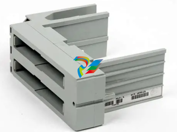
FOXBORO P0926TM Control module
-
 FOXBORO P0916BX Termination Assembly
 -
.jpg) FOXBORO P0916AE P0916AG P0916AW Thermal resistance input type DCS card module
FOXBORO P0916AE P0916AG P0916AW Thermal resistance input type DCS card module -
 FOXBORO P0916AC FOXBORO distributed control system (DCS) compression terminal assembly
 -
.jpg) FOXBORO P0912CB High-performance interface module
FOXBORO P0912CB High-performance interface module -
.jpg) FOXBORO P0911VJ Thermal resistance input output module
FOXBORO P0911VJ Thermal resistance input output module -
.jpg) FOXBORO P0911QH-A High-precision module
FOXBORO P0911QH-A High-precision module -
 FOXBORO P0911QB-C P0911QC-C Thermal resistance input/output module
 -
 FOXBORO P0904BH P0904FH P0904HB Distributed Control system (DCS) module
 -
 FOXBORO P0903ZP P0903ZQ Embedded System Debugging Module
 -
 Foxboro P0903ZL P0903ZN Industrial power module
 -
 Foxboro P0903ZE I/A Series Fieldbus Isolator Module
 -
 FOXBORO P0903NW Industrial Control Module
 -
.jpg) FFOXBORO P0903NQ Industrial power module
FFOXBORO P0903NQ Industrial power module -
 FFOXBORO P0903AA Control Module
 -
 FOXBORO P0400DL Digital output module
 -
.jpg) FOXBORO P0400BJ Digital output module
FOXBORO P0400BJ Digital output module -
 FOXBORO GW30 industrial control module
 -
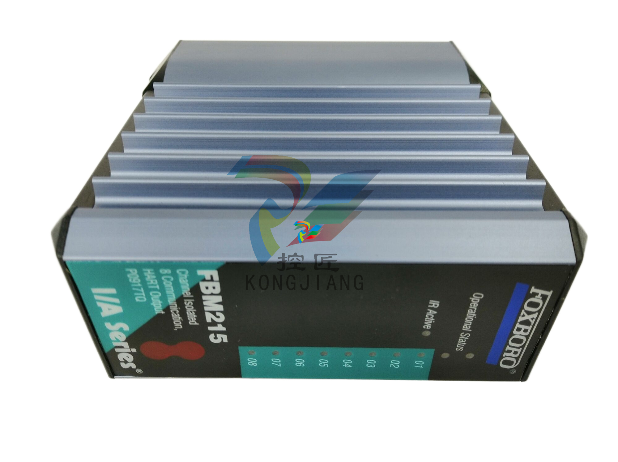
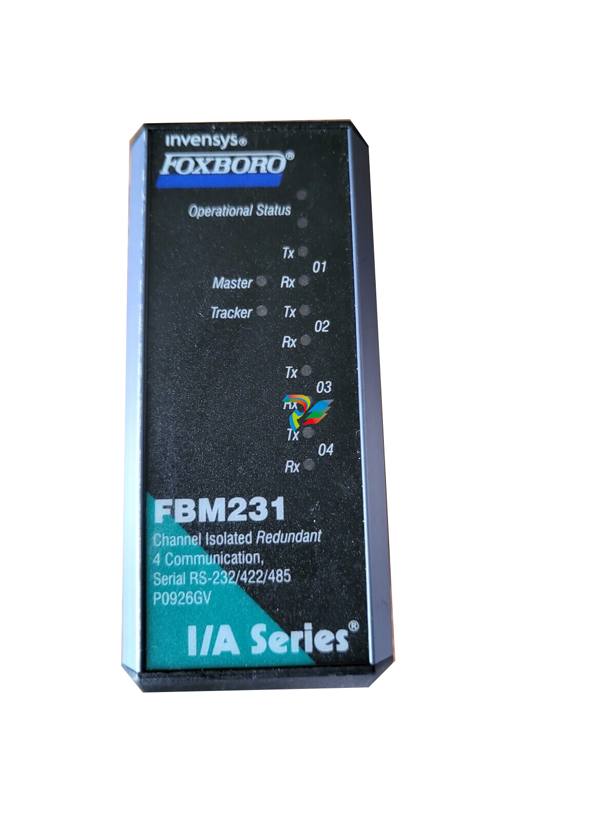 FOXBORO FBM231 Communication Output Module
 -
 FOXBORO Fieldbus Communications Module, FCM10Ef
 -
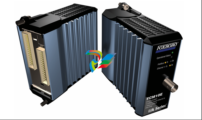 FOXBORO Fieldbus Communications Module, FCM10E


