
ABB ACS850 general-purpose frequency converter
give safety instructions for the installation, commissioning, operation and maintenance of the drive module.
Introduction to the manual introduces the manual
Operation principle and hardware description describes the drive module.
Planning the cabinet installation guides in planning drive cabinets and installing the drive module into a user-defined cabinet. The chapter gives cabinet layout examples and free space requirements around the module for cooling.
Planning the electrical installation instructs in the motor and cable selection, protections and cable routing
Installation describes how to install the drive module into a cabinet and connect the cables to the drive.
Start-up refers to the start-up instructions of the cabinet-installed drive
e. Fault tracing describes the LED indications and refers to the fault tracing instructions of the drive. Maintenance contains preventive maintenance instructions. Technical data contains the technical specifications of the drive module, eg, the ratings, sizes and technical requirements, provisions for fulfilling the requirements for CE and other markings. Dimension drawings contains dimension drawings of the drive module installed into a Rittal TS 8 cabinet. Example circuit diagram shows an example circuit diagram for a cabinet-installed drive module. Resistor braking describes how to select, protect and wire brake resistors. du/dt filters describes how to select du/dt filters for the drive. Categorization by frame size and option code The instructions, technical data and dimension drawings which concern only certain drive frame sizes are marked with the symbol of the frame size (G1 or G2). The frame size is marked on the type designation label. The instructions and technical data which concern only certain optional selections are marked with option codes, eg, +H381. The options included in the drive can be identified from the option codes visible on the type designation label. The option selections are listed in section Type designation key on page 35. Quick installation, commissioning and operating flowchart Task See Plan the installation. Check the ambient conditions, ratings, required cooling air flow, input power connection, compatibility of the motor, motor connection, and other technical data. Select the cables. Planning the cabinet installation (page 37) Planning the electrical installation (page 49) Technical data (page 125) Resistor braking (page 155) Option manual (if optional equipment is included) Unpack and check the units. Check that all necessary optional modules and equipment are present and correct. Only intact units may be started up. Moving and unpacking the unit (page 74) Checking the delivery (page 76) If the drive module has been non-operational for more than one year, the converter DC link capacitors need to be reformed. (Reforming the capacitors, page 12
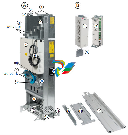
Item Description A Drive module 1 Lifting lugs 2 Fastening bracket 3 Input cable connection busbars and optional DC+ and DC- busbars (+H356) 4 Circuit board compartment 5 Power supply and fiber optic cables to be connected to the external control unit 6 Output cable connection busbars and optional brake resistor connection busbars (+D150) 7 PE terminal 8 Control cable duct 9 Main cooling fans 10 Pedestal 11 Retractable support legs
Item Description
12 Base fastening screws 13 Handle for pulling the drive module out of the cabinet 14 Pedestal guide plate 15 Telescopic extraction and insertion ramp 16 Top guide plate 17 Optional common mode filter (+E208) 18 Grounding busbar B Control unit (JCU) 1 Control unit with front cover 2 Control unit with front cover removed 3 Control cable clamp plate
Resistor braking
What this chapter contains This chapter describes how to select, protect and wire brake resistors. Availability of brake choppers and resistors Brake choppers are optionally available as built-in units, indicated in the type description by +D150. External resistors are available on request from ABB. When is resistor braking needed Typically, a drive system is equipped with brake choppers and resistors if: • high capacity braking is needed and the drive cannot be equipped with a regenerative supply unit • a backup for the regenerative supply unit is needed. Operation principle The energy generated by the motor during a fast deceleration of the drive typically causes the voltage to rise in the drive module intermediate DC circuit. The chopper connects the brake resistor to the intermediate DC circuit whenever the voltage in the circuit exceeds its maximum limit. Energy consumption by the resistor losses lowers the voltage until the resistor can be disconnected. Planning the braking system Selecting the brake circuit components 1. Calculate the maximum power (Pmax) generated by the motor during braking. 2. Select a suitable drive and brake resistor combination for the application according to the rating table on page 159. Take also account of other factors in the drive selection. The braking power must be greater than or equal to the maximum power generated by the motor during braking: 3. Check the resistor selection. The energy generated by the motor during a 400- second period must not exceed the resistor heat dissipation capacity ER. Note: If the ER value is not sufficient, it is possible to use a four-resistor assembly in which two standard resistors are connected in parallel, two in series. The ER value of the four-resistor assembly is four times the value specified for the standard resisto
-
 Beckhoff C6640-0040 Control Cabinet Industrial PC 7-Slot
 -
 BECKHOFF CONTROL CABINET INDUSTRIAL PC - C6930-1062-0050
 -
 Beckhoff Automation EtherCAT Terminal EK1100 EK1122
 -
 Beckhoff CP6533-0001-0060 IPC
 -
 Beckhoff EK9500 | EtherNet/IP™ Bus Coupler
 -
 Beckhoff CP6202-1047-0050 - An industrial-grade embedded panel computer.
 -
 Beckhoff C6650-0040 Industrial PC
 -
 BECKHOFF CX5230-0185 / 000119805 PLC Module
 -
 BECKHOFF EL4732 | EtherCAT Terminal, 2-channel analog output, voltage, ±10 V, 16 bit, oversampling
 -
 Beckhoff CP6202-0001-0010 Economy Built-In Panel
 -
 Beckhoff AX5206-0000-0202 Digital Compact Servo Drives 2-channel
 -
 Beckhoff CP6606-0001-0020 7-inch Economy Panel PC
 -
 Beckhoff CPU basic module CX2020-0155 + power supply module CX2100-0004
 -
 Beckhoff CP2913-000 Multi-Touch Display
 -
 Beckhoff CP6500-1012-0060 14250369 Control Cabinet
 -
 Beckhoff CP7902-0001-0000 Economy Control Panel with DVI/USB Extended interface
 -
 Beckhoff C6920-0010 Control cabinet Industrial PC
 -
 BECKHOFF C3640-0050 Build-in Industrial PCs
 -
 Beckhoff KL6023-0000 KL6023 EnOcean Wireless-Adapter
 -
 Kollmorgen AKM54G-ANC2DB00 servo motor
 -
 Kollmorgen AKD-P00606-NBCN-0000 Servo Drive
 -
Kollmorgen S200 Series S20350-VTS SERVO DRIVE
-
 KOLLMORGEN AKD-P00606-NBCC-I000 SERVO DRIVE
 -
 Kollmorgen MV65WKS-CE310/22PB Servo Drive Control Module
 -
 Kollmorgen S20360-VTS-021 Servo Drive
 -
 KOLLMORGEN CR06550 High-precision digital servo amplifier
 -
 KOLLMORGEN DBL5N01050-03S-VV0-S40 3-Phase AC Synchronous Brushless Servo Motor
 -
 KOLLMORGEN S70301-NANANA-024 SERVO DRIVE
 -
 Kollmorgen S20360-VTS S200 Series Servo Drive
 -
 Kollmorgen RBE-03011-A00 Brushless Frameless Servo Motor
 -
 KOLLMORGEN AKD-T00306-NBAN-0000 INPUT SERVO DRIVE
 -
 KOLLMORGEN S700 Servo Controller S70302-NANANA
 -
 Kollmorgen AKD-P00607-NBEC-0000 400/480VAC 4.40KVA Servo Drive.
 -
 KOLLMORGEN S70102-NANANA SERVO DRIVE
 -
 KOLLMORGEN AKM21E-ANSNEH02 PM Servo Motor & PRD-AMPE25EB-00 Servo Drive Array
 -
 KollMorgen SC1R06260 Servo Drive 1.4/2.2 KVA 115230 Vac
 -
 Kollmorgen AKD-P00306-NBAN-0000 Servo Drive
 -
Kollmorgen TTB2-2042-3052-A DC Motor Industrial Drive 5.5A 185 oz/in
-
 KOLLMORGEN SERVOSTAR 610-AS SERVO AMPLIFIER_SERVOSTAR610AS_S61001
 -
 KOLLMORGEN PRD-0016400P-10 & PRD-0016600D-30 Axis Control System Modules
 -
KOLLMORGEN Seidel DBL5N01700-03S-000-S40 Servo Motor
-
 Hirschmann RS20-1600M2T1SDAEHH03.1.02 Rail Switch
 -
 Hirschmann BRS30-24TX Industrial Rail Switch
 -
 Hirschmann RSPM20-4T14T1EV9HHS999.9.99 Managed Ethernet Switch
 -
 Hirschmann BELDEN RS40-0009CCCCSDAPHH09.0.14 / RS400009CCCCSDAPHH09014
 -
Hirschmann RS40 Rail Switch RS40-0009CCCCSDAE
-
 Hirschmann BELDEN RS30-0802T1T1SDAP / RS300802T1T1SDAP Fully Managed Layer 2 Compact Rail Switch
 -
 Hirschmann BELDEN RS20-0800M2M2SDAUHH / RS200800M2M2SDAUHH
 -
 Hirschmann EAGLE30-04022O6TT999SCCY9HSE3F Industrial Firewall Router Switch
 -
 Hirschmann RS20-1600T1T1SDAEHH09.0.14 RS20 Rail Mount Ethernet Switch
 -
 Hirschmann EAGLE0200T1T1TDDY90000HHE05.3.03 Industrial Security Router
 -
Hirschmann - BELDEN MIPP-AD-1L9P
-
 HIRSCHMANN RSPM20-4Z64Z6TV9HHS9 942 106-999 RAIL SAFETY SWITCH
 -
 HIRSCHMANN FIBEROPTIC MODULE FIP P/N: OZDFIPG3T
 -
 HIRSCHMANN RS20-1600M2M2SDAUHH Ethernet rack-mounted switch
 -
 HIRSCHMANN BELDEN RS20-0400T1T1SDAEHH04.0.01 / RS200400T1T1SDAEHH04001
 -
HIRSCHMANN MM2-4FXM3 MICE Media Module
-
HIRSCHMANN RS20-0800M2M2SDAE Industrial Ethernet Rail Switch
-
 Hirschmann RS20-2400T1T1SDAP / RS20-2400T1T1SDAPHH05.0.02
 -
 GE MLJ1005B010H00C MLJ Digital Synchromism Check
 -
 ALSTOM MICROTECH DX21-M2 Digital Excitation Controller
 -
HIRSCHMANN BRS20-1200ZZZZ-STCY99HHSES
-
 HIRSCHMANN MM3-4FXM2 MICE Media Module
 -
Hirschmann RSB20-0800T1T1SAABHH 8Port ENet Rail Switch RSB20
-
 Hirschmann MACH102-8TP Ethernet Switch
 -
 SAACKE DDZ-M marine steam pressure atomizer
 -
 SAACKE SKV-A marine rotary cup atomizer
 -
 SAACKE Seavis HMI05e
 -
 Kollmorgen MMC-SD-2.0-230 Servo Drive 100-240VAC 2KW 10A Output 3PH 100-240VAC
 -
 Kollmorgen Servo drive CR10550
 -
 Kollmorgen AKD-P01207-NACN-0054 Servo Driver
 -
 Kollmorgen S406M-CA-036 Servostar
 -
.png) Kollmorgen AKD-B02407-NAAN-0000 Digital Servo Drive
Kollmorgen AKD-B02407-NAAN-0000 Digital Servo Drive -
 Kollmorgen SERVOSTAR S406AM-CA Digital Servo Drive
 -
 KOLLMORGEN SERVOSTAR 603-AS SERVO AMPLIFIER_SERVOSTAR603AS_S60301
 -
Kollmorgen S700 Servo Controller (S70602-NANANA-NA)
-
 Kollmorgen MPK411 controller
 -
 KOLLMORGEN MMC-SD-1.3-460-D Smart Drive
 -
 KOLLMORGEN AKM21C-CKB2AA-00 / AKM21CCKB2AA00 Servomotor
 -
 BECKHOFF AX5106-0000-0200 | Digital Compact Servo Drives 1-channel
 -
 BECKHOFF C3620-0000 INDUSTRIAL COMPUTER (MOTORSHELVES)
 -
 Beckhoff EK1960-0000 TwinSAFE Compact Controller
 -
 Beckhoff C6930-0050 Control Cabinet Industrial PC
 -
 Beckhoff CP7711-0001-0030 Industrial Computer Detection
 -
 Beckhoff CX1001-0111 Embedded PC CPU Module
 -
 Beckhoff C6017-0020 | Ultra-compact Industrial PC
 -
 Beckhoff EK1322 | 2-port EtherCAT P junction with feed-in
 -
 Beckhoff CP2219-0010 Panel
 -
 BECKHOFF C6015-0020 ULTRA COMPACT INDUSTRIAL PC
 -
 BECKHOFF CX2030-0120/Standard CPU Module Embedded PC Windows PLC controller
 -
 Beckhoff CP7721-1090-0020 Panel PC
 -
 Beckhoff PC CPU Module CX5130-0175
 -
 Beckhoff C6920-0050 Control Cabinet
 -
 Beckhoff EL6631 EtherCAT 2-Port Communication Interface, Profinet RT Controller
 -
 Beckhoff CP6202-0001-0060 touch screen panel PC
 -
 Beckhoff CP3916-1002-0000 Multi-Touch Control Panel
 -
 Beckhoff EP1809-0021 | EtherCAT Box, 16-channel digital input, 24 V DC, 3 ms, M8Preferred type
 -
 Beckhoff CX8190 PLC Embedded Industrial PC Ethernet Controller
 -
 Beckhoff CX2100-0914 Power Supply for External
 -
 Beckhoff Automation CP6906-0001-0000 HMI
 -
 Beckhoff EP7342-0002 Module
 -
 Beckhoff CX1020-0112 / CX1100-0910 / CX1020-N010 / CX1100-0003 Windows CPU
 -
 Beckhoff EP7211-0034 EtherCAT Box 1 Channel Motion Interface
 -
 Beckhoff C6240-0030 Control cabinet Industrial PC
 -
 beckhoff motherboard CB1052-0004 CB1052-0004
 -
 Beckhoff AX2006-AS Servo Drive / Variable Frequency Drive
 -
BECKHOFF CP6207-0001-0020 NSMP
-
 Beckhoff C6930-1142-0060 Industrial Computer
 -
 Beckhoff FC7501-0000 interface card
 -
 Beckhoff CX5140-0175 Embedded PC PLC CPU CX5140 Industrial Controller
 -
 Beckhoff CP7802-1100-0010: High-End IP65 Control Panel with DVI/USB Extended Interface
 -
BECKHOFF CP3716-1058-0010 CONTROL PANEL
-
 Beckhoff AX8108-0000 Single-Axis Module
 -
 Beckhoff CU8851-0000 | USB extension, USB Extended 2.0 receiver box
 -
Beckhoff C6017-0030 | Ultra-compact Industrial PC
-
 Beckhoff CX1001-0120/CX10010120.cx1000-n001.cx1000-n000 System Overview
 -
 Beckhoff CPU Module CX5140-0155/4GB CPU Module
 -
 Beckhoff CP6533-0001-005: Built-in Panel PC with High-Definition Multi-Touch Control
 -
 Beckhoff EL5042 | EtherCAT Terminal, 2-channel encoder interface, BiSS® C
 -
 Beckhoff C6920-1080-0040: Premium Control Cabinet Industrial PC
 -
 Beckhoff C6920-0060 | Control cabinet Industrial PC
 -
 Beckhoff Embedded-PC CX5010-1121
 -
 Beckhoff CB3050-0010 Mainboard Motherboard
 -
 Beckhoff PLC module CX1020-0000 Basic CPU module (service phase)
 -
 Beckhoff CP7812-1056-0010 15" Multitouch Display Control Panel
 -
 Beckhoff CX5120-0115 /2GB Controller Module
 -
 Beckhoff CP7201-1000-0000 Industrial Panel PC
 -
 Beckhoff Servo Motor AM8061-0JH1-0000


