
BentlyOperation and Maintenance Manual
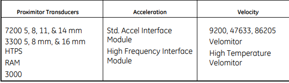
The 3500/42 Proximitor/Seismic Monitor is a four channel monitor that accepts input from Proximitor and Seismic Transducers and uses this input to drive alarms. The monitor can be programmed using the 3500 Rack Configuration Software to perform any of the following functions: Radial Vibration, Thrust Position, Eccentricity, Differential Expansion, Acceleration, and Velocity. The monitor can receive input from many types of transducers including the following Bently Nevada transducers:
The primary purpose of the 3500/42 monitor is to provide 1) machinery protection by continuously comparing current machine vibration against configured alarm setpoints to drive alarms and, 2) essential machine vibration information to both operator and maintenance personnel. Alarm setpoints are configured using the 3500 Rack Configuration Software. Alarm setpoints can be configured for each active proportional value and danger setpoints can be configured for two of the active proportional values. When shipped from the factory, the 3500/42 is delivered unconfigured. When needed, the 3500/42 can be installed into a 3500 rack and configured to perform the required monitoring function. This lets you stock a single monitor for use as a spare for many different applications.
Triple Modular Redundant (TMR) Description
When used in a TMR configuration, 3500/42 monitors and Proximitor/Seismic TMR I/O Modules must be installed adjacent to each other in groups of three. When used in this configuration, two types of voting are employed to ensure accurate operation and to avoid single point failures. The first level of voting occurs on the TMR Relay Module. With this voting, the selected alarm outputs for the three monitors are compared in a 2 out of 3 method. Two monitors must agree before the relay is driven. Refer to the 3500/32 & 34 Relay Module Operation and Maintenance Manual for more information on this voting. The second type of voting is referred to as "Comparison" voting. With this type of voting, the proportional value outputs of each monitor in the group are compared with each other. If the output of one monitor differs from the output of the other monitors in the group by a specified amount, that monitor will add an entry to the System Event list. Configure comparison voting by setting Comparison and % Comparison in the Rack Configuration Software. Comparison: The enabled proportional value of the TMR monitor group that is used to determine how far apart the values of the three monitors can be to each other before an entry is added to the System Event List. % Comparison: The highest allowed percent difference between the middle value of the three monitors in a TMR group and the individual values of each monitor. For TMR applications, two types of input configurations are available: bussed or discrete. Bussed configuration uses the signal from a single nonredundant transducer and provides that signal to all modules in the TMR group through a single 3500 Bussed External Termination Block. Discrete configuration requires three redundant transducers at each measurement location on the machine. The input from each transducer is connected to separate 3500 External Termination Blocks.
Available Data
The Proximitor/Seismic Monitor returns specific proportional values dependent upon the type of channel configured. This monitor also returns both monitor and channel statuses which are common to all types of channels.
Statuses
The following statuses are provided by the monitor. This section describes the available statuses and where they can be found.
Monitor Status OK
This indicates if the monitor is functioning correctly. A not OK status is returned under any of the following conditions: Module Hardware Failure Node Voltage Failure Configuration Failure Transducer Failure Slot ID Failure Keyphasor Failure (if Keyphasor signals are assigned to channel pairs) Channel not OK If the Monitor OK status goes not OK, then the system OK Relay on the Rack Interface I/O Module will be driven not OK.
Alert/Alarm 1
This indicates whether the monitor has entered Alert/Alarm 1. A monitor will enter the Alert/Alarm 1 state when any proportional value provided by the monitor exceeds its configured Alert/Alarm 1 setpoint.
Danger/Alarm 2
This indicates whether the monitor has entered Danger/Alarm 2. A monitor will enter the Danger/Alarm 2 state when any proportional value provided by the monitor exceeds its configured Danger/Alarm 2 setpoint.
Bypass
This indicates when the monitor has bypassed alarming for one or more proportional values at a channel. When a channel bypass status is set, this monitor bypass status will also be set.
-
 ADLINK Multi-Function DAQ PCI-9222/9223
 -
 ADLINK PICMG Single Board Computers NuPRO-A40H
 -
ADLINK HSL-4XMO HSL-4XMO-TB-D103 HSL-4XMO-CD-N-006
-
 ADLINK industrial computer motherboard NuPRO-965DV
 -
 AADLINK PCI-7442 switch card Digital I/O
 -
 ADLINK PCI-7260 Digital I/O
 -
 ADLINK PICMG Single Board Computers NuPRO-852
 -
 ADlink 6U CompactPCI 2.0 Blades cPCI-6840
 -
 Adlink PICMG Single Board Computers NuPRO-935A
 -
 ADLINK ADLINK NuPRO-841 REV:1.0 PICMG Single Board Computers
 -
ADLINK PCI-8254 / PCI-8258 DSP-based 4/8-axis Advanced Motion Controllers
-
 ADLINK NUPRO-780 PICMG Single Board Computers
 -
 ADLINK USB-7230/7250 Isolated USB Digital I/O Modules
 -
 Adlink Technology 51-37111-0C1 cPCI-R8217 cPCI-R3700A PCB Interface Card
 -
 ADLINK DPAC-3020-11(G) Embedded PC Automation Controller
 -
 ADLINK NuPRO-840 PICMG 1.0 industrial Single Board
 -
 Adlink 6U CompactPCI 2.0 Blades cPCI-6965
 -
 ADLINK PCI-9114DG Multi-Function DAQ Card
 -
 Adlink NuPRO-E43 PICMG Single Board Computers
 -
 Adlink PCI-7856 Distributed Motion Control
 -
 ADLINK Mini-ITX Embedded Boards MI-965
 -
 ADLINK NuPRO-E340 industrial control motherboard
 -
 ADLINK NuPRO-595 Series Full-Size PICMG 1.0 SBC
 -
 ADLINK PCIe-GIE64+ / PCIe-GIE62+ 4 / 2-CH PCI Express® Power over Ethernet Frame Grabbers
 -
 ADLINK CPCI-6910AM-M1G 6U Dual Core Xeon CompactPCI Universal SBC
 -
 ADLINK/AMPRO CM-435-v2/CM-435 Extreme Rugged™ PC/104 Single Board Computer
 -
 ADLINK Technology 51-37111-0C1 PCB Interface Card
 -
 Adlink Centralized Motion Controllers PCI-8164
 -
 ADLINK PCI-7230/33/34 32-CH Isolated DIO PCI Cardsrd
 -
 ADLINK NUPRO-E320DV/NUPRO-E320 industrial control motherboard
 -
 Adlink PCI-8154 Advanced 4-axis Servo & Stepper Motion Controller
 -
 Adlink cPCI-3534/3538-S Series 4/8-port Asynchronous Serial Communications Modules
 -
 ADLINK Adlink Digital I/O PCI-7396
 -
 ADLINK 6U Rear Transition Modules cPCI-R6700 Series
 -
 ADLINK cPCI-6700B Industrial Control Board
 -
ADLINK NuPRO-965/ NuPRO-965LV PICMG Single Board Computers
-
 ADLINK HSL-DI16DO16-M-NN 16-CH Discrete Input 16-CH Discrete Output Module
 -
 Adlink cPCI-6770 6U CompactPCI 2.0 Blades
 -
 ADLINK NuPRO-598 REV A1 INDUSTRIAL CONTROL MOTHERBOARD
 -
 ADLINK PCI-7200 PCI Motion Control Card Acquisition Card 51-12001-0C20
 -
 ADLINK TECHNOLOGY EOS-1200/M4G/SSD32G(G) Industrial Systems
 -
 ADLINK Centralized Motion Controllers PCI-8134
 -
 ADLINK cPCI-HR6847E/M2G-1 COMPACT PCI BOARD
 -
 ADLINK PXIE-8638 BUS EXPANSION MODULE
 -
 ADLINK cPCI-6910 6U CompactPCI 2.0 Blades
 -
 Adlink NuPRO-E42 51-41808-0A30 Industrial Motherboard
 -
 ADLINK IH61-AA400-A4A1E (IMB-M40H) Industrial Motherboard
 -
 ADLINK PCIe-GIE64+ GigE Vision Frame Grabber Card
 -
 ADLINK MXC-6322D(G) Industrial Fanless Computer working
 -
ADLINK CPCI-7300 32-CH 80 MB/s High-Speed Digital I/O Module
-
Adlink cPCI-8168 Advanced 6U Compact PCI 8-Axis Motion Controller
-
 Adlink VME CPU Board cPCI-6626/2710/M4G
 -
 ADLINK cPCI-R6200 high-performance 6U CompactPCI Rear Transition Module (RTM)
 -
Adlink cPCI-7248 48-CH Opto-22 Compatible Digital I/O Module
-
 ADLINK DLAP-211-JNX/DLAP-211-JT2/ DLAP-211-Nan
 -
ADLINK cPCI-3544 4-Port RS-422/485 Isolated Serial Communications Card
-
 Hirschmann MSP30-16040SCZ999HHE2A Manage the basic unit of the industrial DIN-Rail switch
 -
Hirschmann MSP30-16040SCY999HHE2A
-
 Hirschmann RS20-0400S2S2SDAEHC09.0.00 Management-type industrial fast Ethernet switch
 -
 Hirschmann Belden OCTOPUS OS20-002800T5T5T5-TBBY999GMSE3S Manageable industrial Ethernet switch
 -
 HIRSCHMANN OS20-000800T5T5T5-TBBU999H5SE2S
 -
 HIRSCHMANN RS20-0800M4M4SDAEHC09.0.14 industrial switch
 -
 Hirschmann RS20-0800T1T1SDAUHC RS20-0800T1T1SDAE
 -
 Hirschmann MSM20-M2M2M2M2SY9HH9E99.9 Fast Ethernet Media Module
 -
 HIRSCHMANN RS30-1602T1T1SDAEHC09.0.10 industrial switch
 -
 HIRSCHMANN MAR1040-4C4C4C4C9999SMMHPHH Managed Etherne
 -
 HIRSCHMANN MAR1040-4C4C4C4C9999SM9HRHH Managed Etherne
 -
 HIRSCHMANN MAR1040-4C4C4C4C9999SM9HPHH05.1.00 industrial switch
 -
 HIRSCHMANN MM20-P9P9M2T1SAHH Fast Ethernet media module
 -
 HIRSCHMANN MM20-P9T1T1T1SAHH hot-swappable hybrid media module
 -
 HIRSCHMANN MM20-Z6Z6T1M2SAHH Fast Ethernet media module
 -
 HIRSCHMANN MM20-Z6M2M2T1SAHH Fast Ethernet media module
 -
HIRSCHMANN MM20-Z6Z6Z6T1SAHH media module.
-
 HIRSCHMANN MM20-Z6T1T1T1EBH Fast Ethernet media card.
 -
 Hirschmann MM20-Z6T1T1T1SAHH Hot-swappable fast Ethernet media module
 -
 Hirschmann MM20-Z6Z6M2M2EBH media module
 -
 HIRSCHMANN MM20-Z6Z6T1T1SZHH Technical Datasheet & SEO Guide
 -
 HIRSCHMANN MM20-Z6Z6T1T1EBH Technical Datasheet & Overview
 -
 HIRSCHMANN MM20-Z6Z6Z6Z6SZHH Media Module
 -
 HIRSCHMANN MM20-M4M2M2T1SAHH Media Module
 -
.png) HIRSCHMANN MM20-M4T1M2T1SAHH Media Module
HIRSCHMANN MM20-M4T1M2T1SAHH Media Module -
 HIRSCHMANN MM20-M2M2T1T1EBH Media Module
 -
HIRSCHMANN MM20-M2M2T1T1SAHH Media Module
-
HIRSCHMANN MM20-M2T1T1T1TAHH Media Module
-
HIRSCHMANN MM20-M2T1T1T1EBH Media Module
-
 HIRSCHMANN MM20-M2T1T1T1SAHH Media Module
 -
 HIRSCHMANN MM20-M2M2M2M2EBH Industrial Ethernet Media Module
 -
HIRSCHMANN RS20-1600S2S2SDAEHH09.0.14 Ethernet switch
-
 HIRSCHMANN MSM20-M2M2T1T1SY9HH9E99.9.99
 -
HIRSCHMANN MSM20-M2M2M2M2SY9HH9E Ethernet media modul
-
 HIRSCHMANN SPIDER-PL-20-05T1999999TWVHHHH Industrial Ethernet Rail Switch
 -
 Hirschmann SPIDER-PL-20-07T1M2M299TWVHHHH Industrial ETHERNET Rail Switch
 -
Hirschmann (Belden) RS20-1600M2M2SDAEHC09.1.00 DIN-rail managed industrial Fast Ethernet switch
-
 Hirschmann (Belden) RS30-1602O6O6TDAPHC09.1.00 DIN-rail managed industrial Ethernet switch
 -
 Hirschmann (Belden) RS30-2402O6T1SDAPHH09.0.13 DIN-rail industrial Ethernet switch
 -
Hirschmann (Belden) SPIDER-PL-20-04T1S29999TY9HHHH Ethernet DIN-rail switch
-
 HIRSCHMANN RS20-1600T1T1SDAUHX Switch
 -
 HIRSCHMANN BRS42-0012OOOO-SPCZ99HHSES industrial switch
 -
 Hirschmann RS20-0800S2S2TDHPHH09.0.14 Fast Ethernet DIN rail switch.
 -
HIRSCHMANN MM20-Z6Z6M2M2SAHH Hybrid Fast Ethernet Media Module
-
HIRSCHMANN MM20-Z6Z6T1T1SAHH hot-swappable hybrid Fast Ethernet Media Module
-
 HIRSCHMANN MM20-P9P9T1T1SAHH Hybrid Fast Ethernet Media Module
 -
 HIRSCHMANN MM20-M4T1T1T1SAHH Hybrid Fast Ethernet Media Module
 -
HIRSCHMANN MM20-M4M4T1T1SAHH Hybrid Fast Ethernet Media Module
-
 HIRSCHMANN MM20-M2M2M2M2SZHH Ethernet media module
 -
HIRSCHMANN MM20-M2M2M2M2SAHH Ethernet media module
-
 HIRSCHMANN MM20-T1T1T1T1EBH 4-port Fast Ethernet Copper Cable Media Module
 -
HIRSCHMANN MM20-T1T1T1T1SAHH 4-port Fast Ethernet Copper Cable Media Module
-
HIRSCHMANN MM20-Z6Z6EBH Hot-swappable fast Ethernet media module
-
HIRSCHMANN MM20-Z6Z6SAHH Ethernet media module
-
HIRSCHMANN MM20-Z6Z6Z6Z6EBH Industrial Media Module
-
 MSM40-T1T1T1TZ9HH9E99.9.99 HIRSCHMANN Switch
 -
 HIRSCHMANN MS20-0800SAAEHC / MS20-0800SAAEHC0 8-port modular Layer 2 management Ethernet switch
 -
 Hirschmann RSPM20-4T14T1SZ9HHS9 Switch RSPM20-4T14T1SZ9HHS9
 -
 HIRSCHMANN RS20-1600M2M2SDAEHH09.1. RS20/30/40 Managed Switch configurator
 -
HIRSCHMANN RS20-1600M2M2SDAEHX09.0.00 Ethernet switch
-
 HIRSCHMANN BELDEN SPIDER-PL-20-07T1M2M299TY9HHHH / SPIDERPL2007T1M2M299TY9HHHH
 -
HIRSCHMANN MM3-1FXS2/3TX1 Switching Board Module
-
HIRSCHMANN RSPE30-24044O7T99-ECCP999HHSE2A08.1.00 Industrial-grade fanless management-type Ethernet switch
-
 HIRSCHMANN RS30-1602OOZZSDAEHC09.1.00 DIN-rail-mounted managed Layer 2 Ethernet switch
 -
 HIRSCHMANN MACH104-20TX-F Managed 24-port Full Gigabit 19" Switch
 -
 HIRSCHMANN Switch RS20-0800M4M4SDAE
 -
Hirschmann RS30-1602O6O6SDAEHH09.1. Management-type Ethernet switch
-
 Hirschmann RS30-1602OOZZSDAEHC09.0.10 Open rack-style Ethernet switch
 -
 HIRSCHMANN RSPE30-24044O7T99-SCCV999HHSI2SXX.X.XX High-Availability Seamless Redundancy
 -
HIRSCHMANN RSPE30-24044O7T99-SCCZ999HHSE2A DIN-rail Ethernet switch
-
HIRSCHMANN MM2-4TX1-EEC switch
-
HIRSCHMANN MSM40-T1T1T1T1TZ9HH9E99.9.99 Module


