
A-BPowerFlex 7000 Medium Voltage AC Drive Air-Cooled (’B’ Frame)—ForGe Control
Important User Information
Read this document and the documents listed in the additional resources section about installation, configuration, and
operation of this equipment before you install, configure, operate, or maintain this product. Users are required to familiarize
themselves with installation and wiring instructions in addition to requirements of all applicable codes, laws, and standards.
Activities including installation, adjustments, putting into service, use, assembly, disassembly, and maintenance are required to
be carried out by suitably trained personnel in accordance with applicable code of practice.
If this equipment is used in a manner not specified by the manufacturer, the protection provided by the equipment may be
impaired.
In no event will Rockwell Automation, Inc. be responsible or liable for indirect or consequential damages resulting from the use
or application of this equipment.
The examples and diagrams in this manual are included solely for illustrative purposes. Because of the many variables and
requirements associated with any particular installation, Rockwell Automation, Inc. cannot assume responsibility or liability for
actual use based on the examples and diagrams.
No patent liability is assumed by Rockwell Automation, Inc. with respect to use of information, circuits, equipment, or software
described in this manual.
Reproduction of the contents of this manual, in whole or in part, without written permission of Rockwell Automation, Inc., is
prohibited.
Throughout this manual, when necessary, we use notes to make you aware of safety considerations.
About This Publication This document provides procedural information for managing daily or
recurring tasks involving the PowerFlex® 7000 medium voltage ‘B’ frame
drives (heatsink and heatpipe models).
Download Firmware, AOP,
EDS, and Other Files
Download firmware, associated files (such as AOP, EDS, and DTM), and access
product release notes from the Product Compatibility and Download Center at
rok.auto/pcdc.
Summary of Changes This publication contains the following new or updated information. This list
includes substantive updates only and is not intended to reflect all changes.

Who Should Use This
Manual
This manual is intended for use by personnel familiar with medium voltage
and solid-state variable speed drive equipment. The manual contains material
that enables regular operation and maintenance of the drive system.
What Is Not in This Manual This manual provides information specific to maintaining the PowerFlex 7000
‘B’ frame drive. This document does not include topics such as:
• Physically transporting or siting the drive cabinetry
• Installing or commissioning procedures
• Spare parts lists compiled for your order.
Rockwell Automation provides the site- and installation-specific electrical and
design information for each drive during the order process cycle. If they are
not available on site with the drive, contact Rockwell Automation.
If you have multiple drive types or power ranges, ensure you have the correct
documentation for each specific PowerFlex 7000 product:
• ‘A’ frame for lower-power air-cooled, configurations (up to
approximately 1250 hp/933 kW)
• ‘B’ frame for higher-power, air-cooled configurations (standard or
heatpipe models)
• ‘C’ frame for all liquid-cooled configurations
PowerFlex 7000 Drive Overview
The PowerFlex™ 7000 drive is a general-purpose, standalone, medium voltage
drive that controls speed, torque, direction, starting, and stopping of standard
asynchronous or synchronous AC motors. This drive works on numerous
standard and specialty applications such as fans, pumps, compressors, mixers,
conveyors, kilns, fan-pumps, and test stands in industries such as
petrochemical, cement, mining and metals, forest products, power generation,
and water/waste water.
The PowerFlex 7000 drive meets most common standards from these
organizations:
• National Electrical Code (NEC)
• International Electrotechnical Commission (IEC)
• National Electrical Manufacturers Association (NEMA)
• Underwriters Laboratories (UL)
• Canadian Standards Association (CSA).
The drive is available with the world’s most common supply voltages at
medium voltage, from 2400…6600V. The design focuses on high reliability,
ease of use, and lower total cost of ownership.
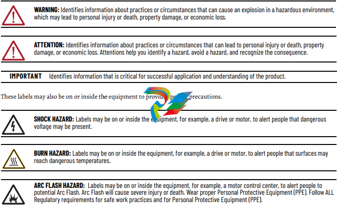
Topology The PowerFlex 7000 drive uses a pulse width modulated (PWM) – current
source inverter (CSI) topology. This topology applies to a wide voltage and
power range. The power semiconductor switches used are easy-to-series for
any medium voltage level. Semiconductor fuses are not required for the power
structure due to the current limiting DC link inductor.
With 6500V PIV rated power semiconductor devices, the number of inverter
components is minimal. For example, only six inverter switching devices are
required at 2400V, 12 at 3300…4160V, and 18 at 6600V.
The PowerFlex 7000 drive also provides inherent regenerative braking for
applications where the load is overhauling the motor, or where high inertia
loads are quickly slowed down. The drive uses the following:
• Symmetrical gate commutated thyristors (SGCTs) for machine converter
switches
• SGCTs for active front-end (AFE) rectifier configurations for the line
converter switches
• Silicon-controlled rectifiers (SCRs) for 18-pulse rectifier configurations
The PowerFlex 7000 drive provides a selectable option for enhanced torque
control capabilities and increased dynamic control performance. This highperformance torque control (HPTC) feature delivers 100% torque at zero speed
and provides torque control through zero speed with smooth direction
transition.
Rectifier Designs Configurations
The PowerFlex 7000 drive offers three rectifier configurations for ‘B’ frame
drives:
• Direct-to-Drive™ (AFE rectifier with integral line reactor and CMC)
• AFE rectifier with separate isolation transformer
• 18-pulse rectifier with separate isolation transformer
Direct-to-Drive
Direct-to-Drive technology does not require an isolation transformer or
multiple rectifier bridges as in voltage source inverter (VSI) topologies offered
by others. The approach is completely different. Instead of multiple
uncontrolled rectifiers, a single AFE rectifier bridge is supplied. The rectifier
semiconductors that are used are SGCTs. Unlike the diodes that are used in
VSI rectifier bridges, SGCTs are turned on and off by a gating signal. A PWM
gating algorithm controls the firing of the rectifier devices, similar to the
control philosophy of the inverter. The gating algorithm uses a specific
42-pulse switching pattern called selective harmonic elimination (SHE) to
mitigate the 5th, 7th, and 11th harmonic orders
A small integral line reactor and capacitor addresses the high harmonic orders
(13th and above) and provides virtually sinusoidal input voltage and current
waveforms back to the distribution system. This configuration delivers
excellent line-side harmonic and power factor performance to meet IEEE 519-
1992 requirements and other global harmonic standards in virtually all cases.
This setup also provides a simple, robust power structure that maximizes
uptime by minimizing the number of discrete components and the number of
interconnections required.
A CMC mitigates the common mode voltage seen at the motor terminals, so
standard (non-inverter duty rated) motors and motor cables can be used. This
technology is ideal for retrofitting existing motor applications
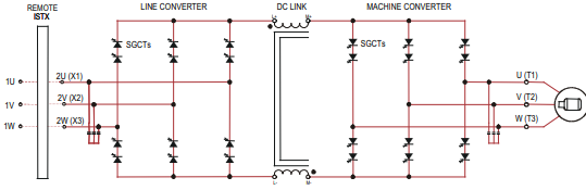
AFE Rectifier with Separate Isolation Transformer
For applications when the line voltage is higher than the motor voltage, a
transformer is required for voltage matching. In this case, providing an AFE
rectifier with a separate isolation transformer is ideal (indoor and outdoor
transformer versions are offered). The isolation transformer replaces the
requirement for an integral line reactor and replaces the requirement for a
CMC that is supplied in the Direct-to-Drive rectifier configuration. However,
the AFE rectifier, its operation, and advantages are the same as the Direct-toDrive configuration.
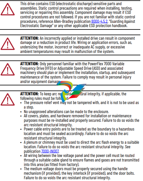
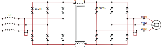
Figure 3 - 3300/4160 AFE Rectifier with Separate Isolation Transformer
For high power constant torque applications and/or when the line voltage is
higher than the motor voltage, a transformer is required for voltage matching
(indoor and outdoor transformer options are available). The 18-pulse rectifier
uses SCRs instead of the SGCTs used for an AFE rectifier. When used for high
power constant torque applications, the 18-pulse rectifier has lower losses than
the AFE rectifier, making 18-pulse ideal for the highest power requirements.
The 18-pulse isolation transformer provides the required input impedance and
addresses common mode voltage just like the separate isolation transformer
used with the AFE rectifier. However, instead of a PWM rectifier switching
pattern and a single rectifier bridge, the 18-pulse configuration mitigates line
side harmonics through harmonic current cancellation in the isolation
transformer phase shifted secondary windings. The inverter is the same
configuration for all available rectifier options.
Figure 4 - 3300/4160V 18-pulse Rectifier with Separate Isolation Transformer
Cooling Technology These VFDs are supplied with heatsinks for most configurations and heatpipes
for the highest-power AFE configurations. While both configurations draw
heat away from the semiconductors, heatpipes are bigger, more efficient, and
require larger fans and airflow.
Information and graphics in this manual show both configurations.
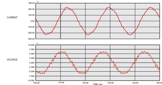
Motor Compatibility The PowerFlex 7000 drive achieves near-sinusoidal current and voltage
waveforms to the motor, resulting in no significant additional heating or
insulation stress. Temperature rise in the motor connected to the VFD is
typically 3 °C (5.5 °F) higher compared to across-the-line operation. Voltage
waveform has dv/dt of less than 50 V/μs. The peak voltage across the motor
insulation is the rated motor RMS voltage divided by 0.707.
Reflected wave and dv/dt issues often associated with VSI drives are a nonissue with the drive. Figure 5 shows typical motor waveforms. The drive uses a
SHE pattern in the inverter to eliminate major order harmonics, plus a small
output capacitor (integral to the drive) to eliminate harmonics at higher
speeds.
Standard motors are compatible without de-rating, even on retrofit
applications.
Motor cable distance is virtually unlimited. Rockwell Automation has tested
this technology for controlling motors up to 15 km (9.3 mi) away from the drive.
Figure 5 - Motor Waveforms at Full Load, Full Speed
Power Component Definition and Maintenance
This section provides an overview of the control components and cabling of
your PowerFlex® 7000 ‘B’ frame drive. This section also details a number of
regular or recurring maintenance tasks that will keep your drive in peak
operating condition.
Figure 20 through Figure 26 identify the control components and cabling of
your drives. Where appropriate, separate diagrams and instructions are
available for both the heatsink and the heatpipe ‘B’ frame models.
For information regarding power wiring and cabling connections (as might be
necessary for routine maintenance), see the PowerFlex 7000 ‘B’ frame
installation manual, publication 7000-IN007.
Control Power Off Tests Perform the following checks before applying control power to the drive.
Rockwell Automation recommends that you complete these checks in the
sequence they are presented here.
Interlocking
When the input contactor option is purchased, a key interlock is provided to
prevent access to the medium voltage compartments of the drive unless the
input isolation switch is locked in the open position.
Where the input switching device is provided by others, Rockwell Automation
will provide a key interlock on the medium voltage compartment of the drive,
and a matching interlock for installation by others on the upstream device. The
interlock shall be installed in a manner that ensures the power to the drive is
off and the drive is electrically isolated whenever the key is freed.
Although key interlocks shipped with all medium voltage equipment are
aligned in the factory, they often move out of position during shipping or are
often misaligned when the cabinet is set down on an uneven floor.
ATTENTION: Servicing energized industrial control equipment can be
hazardous. Severe injury or death can result from electrical shock,
burn, or unintended actuation of control equipment. Hazardous
voltages can exist in the cabinet even with the circuit breaker in the
off position. We recommend that you disconnect or lock out control
equipment from power sources, and confirm discharge of stored
energy in capacitors. If you must work in the vicinity of energized
equipment, the safety-related work practices of NFPA 70E, Standard
for Electrical Safety in the Workplace, must be followed
-
 Hirschmann RS20-1600M2T1SDAEHH03.1.02 Rail Switch
 -
 Hirschmann BRS30-24TX Industrial Rail Switch
 -
 Hirschmann RSPM20-4T14T1EV9HHS999.9.99 Managed Ethernet Switch
 -
 Hirschmann BELDEN RS40-0009CCCCSDAPHH09.0.14 / RS400009CCCCSDAPHH09014
 -
Hirschmann RS40 Rail Switch RS40-0009CCCCSDAE
-
 Hirschmann BELDEN RS30-0802T1T1SDAP / RS300802T1T1SDAP Fully Managed Layer 2 Compact Rail Switch
 -
 Hirschmann BELDEN RS20-0800M2M2SDAUHH / RS200800M2M2SDAUHH
 -
 Hirschmann EAGLE30-04022O6TT999SCCY9HSE3F Industrial Firewall Router Switch
 -
 Hirschmann RS20-1600T1T1SDAEHH09.0.14 RS20 Rail Mount Ethernet Switch
 -
 Hirschmann EAGLE0200T1T1TDDY90000HHE05.3.03 Industrial Security Router
 -
Hirschmann - BELDEN MIPP-AD-1L9P
-
 HIRSCHMANN RSPM20-4Z64Z6TV9HHS9 942 106-999 RAIL SAFETY SWITCH
 -
 HIRSCHMANN FIBEROPTIC MODULE FIP P/N: OZDFIPG3T
 -
 HIRSCHMANN RS20-1600M2M2SDAUHH Ethernet rack-mounted switch
 -
 HIRSCHMANN BELDEN RS20-0400T1T1SDAEHH04.0.01 / RS200400T1T1SDAEHH04001
 -
HIRSCHMANN MM2-4FXM3 MICE Media Module
-
HIRSCHMANN RS20-0800M2M2SDAE Industrial Ethernet Rail Switch
-
 Hirschmann RS20-2400T1T1SDAP / RS20-2400T1T1SDAPHH05.0.02
 -
 GE MLJ1005B010H00C MLJ Digital Synchromism Check
 -
 ALSTOM MICROTECH DX21-M2 Digital Excitation Controller
 -
HIRSCHMANN BRS20-1200ZZZZ-STCY99HHSES
-
 HIRSCHMANN MM3-4FXM2 MICE Media Module
 -
Hirschmann RSB20-0800T1T1SAABHH 8Port ENet Rail Switch RSB20
-
 Hirschmann MACH102-8TP Ethernet Switch
 -
 SAACKE DDZ-M marine steam pressure atomizer
 -
 SAACKE SKV-A marine rotary cup atomizer
 -
 SAACKE Seavis HMI05e
 -
 Kollmorgen MMC-SD-2.0-230 Servo Drive 100-240VAC 2KW 10A Output 3PH 100-240VAC
 -
 Kollmorgen Servo drive CR10550
 -
 Kollmorgen AKD-P01207-NACN-0054 Servo Driver
 -
 Kollmorgen S406M-CA-036 Servostar
 -
.png) Kollmorgen AKD-B02407-NAAN-0000 Digital Servo Drive
Kollmorgen AKD-B02407-NAAN-0000 Digital Servo Drive -
 Kollmorgen SERVOSTAR S406AM-CA Digital Servo Drive
 -
 KOLLMORGEN SERVOSTAR 603-AS SERVO AMPLIFIER_SERVOSTAR603AS_S60301
 -
Kollmorgen S700 Servo Controller (S70602-NANANA-NA)
-
 Kollmorgen MPK411 controller
 -
 KOLLMORGEN MMC-SD-1.3-460-D Smart Drive
 -
 KOLLMORGEN AKM21C-CKB2AA-00 / AKM21CCKB2AA00 Servomotor
 -
 BECKHOFF AX5106-0000-0200 | Digital Compact Servo Drives 1-channel
 -
 BECKHOFF C3620-0000 INDUSTRIAL COMPUTER (MOTORSHELVES)
 -
 Beckhoff EK1960-0000 TwinSAFE Compact Controller
 -
 Beckhoff C6930-0050 Control Cabinet Industrial PC
 -
 Beckhoff CP7711-0001-0030 Industrial Computer Detection
 -
 Beckhoff CX1001-0111 Embedded PC CPU Module
 -
 Beckhoff C6017-0020 | Ultra-compact Industrial PC
 -
 Beckhoff EK1322 | 2-port EtherCAT P junction with feed-in
 -
 Beckhoff CP2219-0010 Panel
 -
 BECKHOFF C6015-0020 ULTRA COMPACT INDUSTRIAL PC
 -
 BECKHOFF CX2030-0120/Standard CPU Module Embedded PC Windows PLC controller
 -
 Beckhoff CP7721-1090-0020 Panel PC
 -
 Beckhoff PC CPU Module CX5130-0175
 -
 Beckhoff C6920-0050 Control Cabinet
 -
 Beckhoff EL6631 EtherCAT 2-Port Communication Interface, Profinet RT Controller
 -
 Beckhoff CP6202-0001-0060 touch screen panel PC
 -
 Beckhoff CP3916-1002-0000 Multi-Touch Control Panel
 -
 Beckhoff EP1809-0021 | EtherCAT Box, 16-channel digital input, 24 V DC, 3 ms, M8Preferred type
 -
 Beckhoff CX8190 PLC Embedded Industrial PC Ethernet Controller
 -
 Beckhoff CX2100-0914 Power Supply for External
 -
 Beckhoff Automation CP6906-0001-0000 HMI
 -
 Beckhoff EP7342-0002 Module
 -
 Beckhoff CX1020-0112 / CX1100-0910 / CX1020-N010 / CX1100-0003 Windows CPU
 -
 Beckhoff EP7211-0034 EtherCAT Box 1 Channel Motion Interface
 -
 Beckhoff C6240-0030 Control cabinet Industrial PC
 -
 beckhoff motherboard CB1052-0004 CB1052-0004
 -
 Beckhoff AX2006-AS Servo Drive / Variable Frequency Drive
 -
BECKHOFF CP6207-0001-0020 NSMP
-
 Beckhoff C6930-1142-0060 Industrial Computer
 -
 Beckhoff FC7501-0000 interface card
 -
 Beckhoff CX5140-0175 Embedded PC PLC CPU CX5140 Industrial Controller
 -
 Beckhoff CP7802-1100-0010: High-End IP65 Control Panel with DVI/USB Extended Interface
 -
BECKHOFF CP3716-1058-0010 CONTROL PANEL
-
 Beckhoff AX8108-0000 Single-Axis Module
 -
 Beckhoff CU8851-0000 | USB extension, USB Extended 2.0 receiver box
 -
Beckhoff C6017-0030 | Ultra-compact Industrial PC
-
 Beckhoff CX1001-0120/CX10010120.cx1000-n001.cx1000-n000 System Overview
 -
 Beckhoff CPU Module CX5140-0155/4GB CPU Module
 -
 Beckhoff CP6533-0001-005: Built-in Panel PC with High-Definition Multi-Touch Control
 -
 Beckhoff EL5042 | EtherCAT Terminal, 2-channel encoder interface, BiSS® C
 -
 Beckhoff C6920-1080-0040: Premium Control Cabinet Industrial PC
 -
 Beckhoff C6920-0060 | Control cabinet Industrial PC
 -
 Beckhoff Embedded-PC CX5010-1121
 -
 Beckhoff CB3050-0010 Mainboard Motherboard
 -
 Beckhoff PLC module CX1020-0000 Basic CPU module (service phase)
 -
 Beckhoff CP7812-1056-0010 15" Multitouch Display Control Panel
 -
 Beckhoff CX5120-0115 /2GB Controller Module
 -
 Beckhoff CP7201-1000-0000 Industrial Panel PC
 -
 Beckhoff Servo Motor AM8061-0JH1-0000
 -
 BECKHOFF CP6503-0001-0050 Built-in Panel PC
 -
Beckhoff CP3919-0010 Display G190ETN01.2 19" PCT V04. Multi-touch Control Panel
-
 Beckhoff CX5110-0112-9020/000368201 Embedded PC Intel Atom Processor
 -
 Beckhoff AX8206-0000 Dual-Axis Module
 -
Beckhoff Nail Operating Terminal CP7032-1031-0010
-
Beckhoff AM8042-0EH1-0000 Servomotor 4.10 Nm (M0), F4 (87 mm)
-
 Beckhoff EK9300 Beckhoff CPU Module
 -
Beckhoff CP3224-0020 Multitouch-Panel-PC
-
 Beckhoff CP2712-0000 12.1" 24VDC Touch Screen WMD0
 -
 BECKHOFF CX5240-0195 / 0000289234 Embedded PC 40 GB CFast Card
 -
 Beckhoff CP6932-1000-0000 Control Panel
 -
 BECKHOFF CX5120-0121 PLC Module
 -
 Beckhoff EL3218 | EtherCAT Terminal, 8-channel analog input
 -
Beckhoff C6640-0050 | Control cabinet Industrial PC
-
 Beckhoff Cx5130-0120/4GB Embedded-PC
 -
 BECKHOFF CX2030-0122 PLC PROCESSOR
 -
 BECKHOFF CX5020-0122 Controller Module
 -
 Beckhoff CP3915-0000 Multitouch Panel
 -
 BECKHOFF EL3014 | EtherCAT Terminal
 -
 BECKHOFF Industrial Computer c6920-1057-0030
 -
 Beckhoff CX5130-0141/4GB CX5130-0141 Embedded PC
 -
 Beckhoff C6240-1052-0040 4-086-06-3073 Industrial Computer
 -
 Beckhoff CX5140-0135 /4GB High-Performance Embedded Industrial PC
 -
 Beckhoff C6515-1001-0000 Industrial PC
 -
 Beckhoff AX5103-0000-0200 - Digital Compact Servo Drives
 -
 Beckhoff CX2030-0130-1003/4GB Basic CPU module
 -
 Beckhoff AX8620-0000 Power Supply Module
 -
 Beckhoff CX9020-0111 module with
 -
 Beckhoff EL7332 PLC Module
 -
 BECKHOFF CP7709-0001-0020 HMI
 -
 Beckhoff CX5120-0155/2GB Embedded PC
 -
 BECKHOFF CP7037-1037-0010 OPERATOR INTERFACE TOUCHSCREEN
 -
 Beckhoff EK9000 | ModbusTCP/UDP Bus Coupler
 -
 Beckhoff Touch Panel Screen CP6020 -0000-0000
 -
 Beckhoff CX2020-0121 Module FAST Shipping
 -
 Beckhoff CX2030-0125 Basic CPU Module
 -
 Beckhoff CP3918-0000 Multi-Touch 18.5" Control Panel
 -
 Automotion LC4A00010 DC BL Motor Control, ATS, Sub Assy, SCP, 115VAC,
 -
 500T-115VAC - VAS ENGINEERING - DORIC 500 SERIES DIGITAL TEMP INDICATOR
 -
 Honeywell X-DCS2000/EN Digital Integrated System Manager 50/60Hz 100-240V #4
 -
 Kollmorgen S60600 Servostar600 606-Fan 4 kVA, 6 A, 3 X 230 - 480 V


