
ABB SDCS-CON-4 Digital inputs
equipment..
WARNING!
• Only qualified electricians are allowed to install and maintain the drive!
• Never work on the drive, motor cable or motor when main power is applied.
Always ensure by measuring with a multimeter (impedance at least 1 Mohm)
that:
1. Voltage between drive input phases U1, V1 and W1 and the frame is
close to 0 V.
2. Voltage between terminals C+ and D- and the frame is close to 0 V.
• Do not work on the control cables when power is applied to the drive or to the
external control circuits. Externally supplied control circuits may cause
dangerous voltages inside the drive even when the main power on the drive is
switched off.
• Do not make any insulation resistance or voltage withstand tests on the drive or
drive modules.
• Isolate the motor cables from the drive when testing the insulation resistance or
voltage withstand of the cables or the motor.
• When reconnecting the motor cable, always check that the C+ and D- cables
are connected with the proper terminal.
Note:
• The motor cable terminals on the drive are at a dangerously high voltage when
the main power is on, regardless of whether the motor is running or not.
• Depending on the external wiring, dangerous voltages (115 V, 220 V or 230 V)
may be present on the relay outputs of the drive system (e.g. SDCS-IOB-2 and
RDIO).
• DCS800 with enclosure extension: Before working on the drive, isolate the
whole drive from the supply
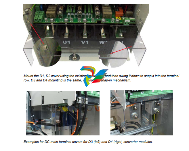
Terminal cover according to VBG 4 regulations
For converter modules size D1 - D4 shrouds for protection against contact are
provided.
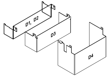 Id No. Id No. | Id No. |
| 3ADT631137P0001 | D1, D2 |
| 3ADV400208P0001 | D3 |
| 3ADV400207P0001 | D4 |
Chapter overview
This chapter contains the instructions that must be followed when selecting the
motor, cables, protections, cable routing and way of operation for the drive system.
Always follow local regulations. This chapter applies to all DCS800 converter
modules.
Attention:
If the recommendations given by ABB are not followed, the drive may experience
problems that the warranty does not cover. See also Technical Guide.
Options
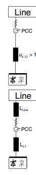
Line reactors (L1)
For armature and field supply.
When thyristor converters operate, the line voltage is short-circuited during
commutation from one thyristor to the next. This operation causes voltage dips in the
mains PCC (point of common coupling). For the connection of a power converter
system to the mains, one of the following configurations applies:
Configuration A
When using a converter, a minimum of impedance is required to
ensure proper performance of the snubber circuit. Use a line reactor
to meet this minimum impedance requirement. The value must
therefore not drop below 1 % uk (relative impedance voltage). It
should not exceed 10 % uk, due to considerable voltage drops at the
converters outputs.
Configuration B
If special requirements have to be met at the PCC (standards like EN
61 800-3, DC and AC drives at the same line, etc), different criteria
must be applied for selecting a line reactor. These requirements are
often defined as a voltage dip in percent of the nominal supply
voltage. The combined impedance of ZLine and ZL1 constitute the total
series impedance of the installation. The ratio between the line
impedance and the line reactor impedance determines the voltage dip
at the PCC. In such cases, line chokes with an impedance around 4 %
are often used.
Example calculation with ukLine = 1 % and ukL1 = 4 %:
Voltage dip = ZLine / (ZLine + ZL1) = 20 %. Detailed calculations see
Technical Guide.
Start, Stop and E-Stop control The relay logic is splitted into four parts: 1: Generation of the On / Off and Start / Stop command: The commands represented by K20 and K21 (latching interface relay) can also be generated by a PLC and transferred to the terminals of the converter either by relays, using galvanic isolation or directly via 24 V signals. There is no need to use hardwired signals. Transfer these commands via serial communication. Even a mixed solution can be realized by selecting different possibilities for the one or the other signal (see parameter group 11). 2: Generation of control and monitoring signals: Control the main contactor K1 for the armature circuit by the dry contact of DO8 located on the SDCS-PIN-4 or SDCS-POW-4. The status of motor (K6) and converter (K8) fans can be monitored by means of MotFanAck (10.06) and ConvFanAck (10.20). 3: Off2 (Coast Stop) and Off3 (E-stop): Beside On / Off and Start / Stop the drive is equipped with two additional stop functions Off2 (Coast Stop) and Off3 (E-stop) according to Profibus standard. Off3 (E-stop) is scalable via E StopMode (21.04) to perform stop category 1. Connect this function to the E-stop push button without any time delay. In case of E StopMode (21.04) = RampStop the K15 timer relay must be set longer than E StopRamp (22.04). For E StopMode (21.04) = Coast the drive opens the main contactor immediately. Off2 (Coast Stop) switches the DC current off as fast as possible and prepares the drive to open the main contactor or drop the mains supply. For a normal DC motor load the time to force the DC current to zero is below 20 ms. This function should be connected to all signals and safety functions opening the main contactor. This function is important for 4-Q drives. Do not open main contactor during regenerative current. The correct sequence is: 1. switch off regenerative current 2. then open the main contactor In case the E-stop push button is hit, the information is transferred to the converter via DI5. In case E StopMode (21.04) = RampStop or TorqueLimit the converter will decelerate the motor and then open the main contactor. If the drive has not finished the function within the K15 timer setting, the drive must get the command to switch off the current via K16. After the K16 timer has elapsed, the main contactor is opened immediately, independent of the drive's status.
-
 Hirschmann RS20-1600M2T1SDAEHH03.1.02 Rail Switch
 -
 Hirschmann BRS30-24TX Industrial Rail Switch
 -
 Hirschmann RSPM20-4T14T1EV9HHS999.9.99 Managed Ethernet Switch
 -
 Hirschmann BELDEN RS40-0009CCCCSDAPHH09.0.14 / RS400009CCCCSDAPHH09014
 -
Hirschmann RS40 Rail Switch RS40-0009CCCCSDAE
-
 Hirschmann BELDEN RS30-0802T1T1SDAP / RS300802T1T1SDAP Fully Managed Layer 2 Compact Rail Switch
 -
 Hirschmann BELDEN RS20-0800M2M2SDAUHH / RS200800M2M2SDAUHH
 -
 Hirschmann EAGLE30-04022O6TT999SCCY9HSE3F Industrial Firewall Router Switch
 -
 Hirschmann RS20-1600T1T1SDAEHH09.0.14 RS20 Rail Mount Ethernet Switch
 -
 Hirschmann EAGLE0200T1T1TDDY90000HHE05.3.03 Industrial Security Router
 -
Hirschmann - BELDEN MIPP-AD-1L9P
-
 HIRSCHMANN RSPM20-4Z64Z6TV9HHS9 942 106-999 RAIL SAFETY SWITCH
 -
 HIRSCHMANN FIBEROPTIC MODULE FIP P/N: OZDFIPG3T
 -
 HIRSCHMANN RS20-1600M2M2SDAUHH Ethernet rack-mounted switch
 -
 HIRSCHMANN BELDEN RS20-0400T1T1SDAEHH04.0.01 / RS200400T1T1SDAEHH04001
 -
HIRSCHMANN MM2-4FXM3 MICE Media Module
-
HIRSCHMANN RS20-0800M2M2SDAE Industrial Ethernet Rail Switch
-
 Hirschmann RS20-2400T1T1SDAP / RS20-2400T1T1SDAPHH05.0.02
 -
 GE MLJ1005B010H00C MLJ Digital Synchromism Check
 -
 ALSTOM MICROTECH DX21-M2 Digital Excitation Controller
 -
HIRSCHMANN BRS20-1200ZZZZ-STCY99HHSES
-
 HIRSCHMANN MM3-4FXM2 MICE Media Module
 -
Hirschmann RSB20-0800T1T1SAABHH 8Port ENet Rail Switch RSB20
-
 Hirschmann MACH102-8TP Ethernet Switch
 -
 SAACKE DDZ-M marine steam pressure atomizer
 -
 SAACKE SKV-A marine rotary cup atomizer
 -
 SAACKE Seavis HMI05e
 -
 Kollmorgen MMC-SD-2.0-230 Servo Drive 100-240VAC 2KW 10A Output 3PH 100-240VAC
 -
 Kollmorgen Servo drive CR10550
 -
 Kollmorgen AKD-P01207-NACN-0054 Servo Driver
 -
 Kollmorgen S406M-CA-036 Servostar
 -
.png) Kollmorgen AKD-B02407-NAAN-0000 Digital Servo Drive
Kollmorgen AKD-B02407-NAAN-0000 Digital Servo Drive -
 Kollmorgen SERVOSTAR S406AM-CA Digital Servo Drive
 -
 KOLLMORGEN SERVOSTAR 603-AS SERVO AMPLIFIER_SERVOSTAR603AS_S60301
 -
Kollmorgen S700 Servo Controller (S70602-NANANA-NA)
-
 Kollmorgen MPK411 controller
 -
 KOLLMORGEN MMC-SD-1.3-460-D Smart Drive
 -
 KOLLMORGEN AKM21C-CKB2AA-00 / AKM21CCKB2AA00 Servomotor
 -
 BECKHOFF AX5106-0000-0200 | Digital Compact Servo Drives 1-channel
 -
 BECKHOFF C3620-0000 INDUSTRIAL COMPUTER (MOTORSHELVES)
 -
 Beckhoff EK1960-0000 TwinSAFE Compact Controller
 -
 Beckhoff C6930-0050 Control Cabinet Industrial PC
 -
 Beckhoff CP7711-0001-0030 Industrial Computer Detection
 -
 Beckhoff CX1001-0111 Embedded PC CPU Module
 -
 Beckhoff C6017-0020 | Ultra-compact Industrial PC
 -
 Beckhoff EK1322 | 2-port EtherCAT P junction with feed-in
 -
 Beckhoff CP2219-0010 Panel
 -
 BECKHOFF C6015-0020 ULTRA COMPACT INDUSTRIAL PC
 -
 BECKHOFF CX2030-0120/Standard CPU Module Embedded PC Windows PLC controller
 -
 Beckhoff CP7721-1090-0020 Panel PC
 -
 Beckhoff PC CPU Module CX5130-0175
 -
 Beckhoff C6920-0050 Control Cabinet
 -
 Beckhoff EL6631 EtherCAT 2-Port Communication Interface, Profinet RT Controller
 -
 Beckhoff CP6202-0001-0060 touch screen panel PC
 -
 Beckhoff CP3916-1002-0000 Multi-Touch Control Panel
 -
 Beckhoff EP1809-0021 | EtherCAT Box, 16-channel digital input, 24 V DC, 3 ms, M8Preferred type
 -
 Beckhoff CX8190 PLC Embedded Industrial PC Ethernet Controller
 -
 Beckhoff CX2100-0914 Power Supply for External
 -
 Beckhoff Automation CP6906-0001-0000 HMI
 -
 Beckhoff EP7342-0002 Module
 -
 Beckhoff CX1020-0112 / CX1100-0910 / CX1020-N010 / CX1100-0003 Windows CPU
 -
 Beckhoff EP7211-0034 EtherCAT Box 1 Channel Motion Interface
 -
 Beckhoff C6240-0030 Control cabinet Industrial PC
 -
 beckhoff motherboard CB1052-0004 CB1052-0004
 -
 Beckhoff AX2006-AS Servo Drive / Variable Frequency Drive
 -
BECKHOFF CP6207-0001-0020 NSMP
-
 Beckhoff C6930-1142-0060 Industrial Computer
 -
 Beckhoff FC7501-0000 interface card
 -
 Beckhoff CX5140-0175 Embedded PC PLC CPU CX5140 Industrial Controller
 -
 Beckhoff CP7802-1100-0010: High-End IP65 Control Panel with DVI/USB Extended Interface
 -
BECKHOFF CP3716-1058-0010 CONTROL PANEL
-
 Beckhoff AX8108-0000 Single-Axis Module
 -
 Beckhoff CU8851-0000 | USB extension, USB Extended 2.0 receiver box
 -
Beckhoff C6017-0030 | Ultra-compact Industrial PC
-
 Beckhoff CX1001-0120/CX10010120.cx1000-n001.cx1000-n000 System Overview
 -
 Beckhoff CPU Module CX5140-0155/4GB CPU Module
 -
 Beckhoff CP6533-0001-005: Built-in Panel PC with High-Definition Multi-Touch Control
 -
 Beckhoff EL5042 | EtherCAT Terminal, 2-channel encoder interface, BiSS® C
 -
 Beckhoff C6920-1080-0040: Premium Control Cabinet Industrial PC
 -
 Beckhoff C6920-0060 | Control cabinet Industrial PC
 -
 Beckhoff Embedded-PC CX5010-1121
 -
 Beckhoff CB3050-0010 Mainboard Motherboard
 -
 Beckhoff PLC module CX1020-0000 Basic CPU module (service phase)
 -
 Beckhoff CP7812-1056-0010 15" Multitouch Display Control Panel
 -
 Beckhoff CX5120-0115 /2GB Controller Module
 -
 Beckhoff CP7201-1000-0000 Industrial Panel PC
 -
 Beckhoff Servo Motor AM8061-0JH1-0000
 -
 BECKHOFF CP6503-0001-0050 Built-in Panel PC
 -
Beckhoff CP3919-0010 Display G190ETN01.2 19" PCT V04. Multi-touch Control Panel
-
 Beckhoff CX5110-0112-9020/000368201 Embedded PC Intel Atom Processor
 -
 Beckhoff AX8206-0000 Dual-Axis Module
 -
Beckhoff Nail Operating Terminal CP7032-1031-0010
-
Beckhoff AM8042-0EH1-0000 Servomotor 4.10 Nm (M0), F4 (87 mm)
-
 Beckhoff EK9300 Beckhoff CPU Module
 -
Beckhoff CP3224-0020 Multitouch-Panel-PC
-
 Beckhoff CP2712-0000 12.1" 24VDC Touch Screen WMD0
 -
 BECKHOFF CX5240-0195 / 0000289234 Embedded PC 40 GB CFast Card
 -
 Beckhoff CP6932-1000-0000 Control Panel
 -
 BECKHOFF CX5120-0121 PLC Module
 -
 Beckhoff EL3218 | EtherCAT Terminal, 8-channel analog input
 -
Beckhoff C6640-0050 | Control cabinet Industrial PC
-
 Beckhoff Cx5130-0120/4GB Embedded-PC
 -
 BECKHOFF CX2030-0122 PLC PROCESSOR
 -
 BECKHOFF CX5020-0122 Controller Module
 -
 Beckhoff CP3915-0000 Multitouch Panel
 -
 BECKHOFF EL3014 | EtherCAT Terminal
 -
 BECKHOFF Industrial Computer c6920-1057-0030
 -
 Beckhoff CX5130-0141/4GB CX5130-0141 Embedded PC
 -
 Beckhoff C6240-1052-0040 4-086-06-3073 Industrial Computer
 -
 Beckhoff CX5140-0135 /4GB High-Performance Embedded Industrial PC
 -
 Beckhoff C6515-1001-0000 Industrial PC
 -
 Beckhoff AX5103-0000-0200 - Digital Compact Servo Drives
 -
 Beckhoff CX2030-0130-1003/4GB Basic CPU module
 -
 Beckhoff AX8620-0000 Power Supply Module
 -
 Beckhoff CX9020-0111 module with
 -
 Beckhoff EL7332 PLC Module
 -
 BECKHOFF CP7709-0001-0020 HMI
 -
 Beckhoff CX5120-0155/2GB Embedded PC
 -
 BECKHOFF CP7037-1037-0010 OPERATOR INTERFACE TOUCHSCREEN
 -
 Beckhoff EK9000 | ModbusTCP/UDP Bus Coupler
 -
 Beckhoff Touch Panel Screen CP6020 -0000-0000
 -
 Beckhoff CX2020-0121 Module FAST Shipping
 -
 Beckhoff CX2030-0125 Basic CPU Module
 -
 Beckhoff CP3918-0000 Multi-Touch 18.5" Control Panel
 -
 Automotion LC4A00010 DC BL Motor Control, ATS, Sub Assy, SCP, 115VAC,
 -
 500T-115VAC - VAS ENGINEERING - DORIC 500 SERIES DIGITAL TEMP INDICATOR
 -
 Honeywell X-DCS2000/EN Digital Integrated System Manager 50/60Hz 100-240V #4
 -
 Kollmorgen S60600 Servostar600 606-Fan 4 kVA, 6 A, 3 X 230 - 480 V


