
OMRON ZFV-NX1 CFP0260 ZFV-A20 VISION CONTROL PANEL
Set value: 5. Upper- and lower-limit with standby sequence
For Upper- and Lower-Limit Alarm Described Above at *2
if the upper-
• In cases 1 and 2 above, the alarm is always OFF
• In case 3. the alarm is always OFF
and lower-limit hysteresis overlaps.
.
*5.Set value: 5. Upper- and lower-limit alarm with standby sequence
The alarm is always OFF
if upper- and lower-limit hysteresis
overlaps.
*6.Refer to the E5@C Digital Temperature Controllers User’s Manual
(Cat. No. H174) for information on the operation of the standby
sequence.
*7.Refer to the E5@C Digital Temperature Controllers User’s Manual
(Cat. No. H174) for information on the LBA.
*8.Refer to the E5@C Digital Temperature Controllers User’s Manual
(Cat. No. H174) for information on the PV change rate alarm.
*9.When heating/cooling control is performed, the MV absolute
value upper-limit alarm functions only for the heating operation
and the MV absolute-value lower-limit alarm functions only for the
cooling operation
The indication accuracy of K thermocouples in the −200 to 1.300°C range, T and N thermocouples at a temperature of −100°C max., and U
and L thermocouples at any temperature is ±2°C ±1 digit max. The indication accuracy of B thermocouples at a temperature of 400°C max. is
not specified. The indication accuracy of B thermocouples at a temperature of 400 to 800°C is ±3°C max.
The indication accuracy of R and S thermocouples at a temperature of 200°C max. is ±3°C ±1 digit max. The indication accuracy of C/W
thermocouples is (±0.3% of PV or ±3°C, whichever is greater) ±1 digit max.
The indication accuracy of PLII thermocouples is (±0.3% of PV or ±2°C, whichever is greater) ±1 digit max.
*2.However, the precision between 0 and 4 mA for a 0 to 20 mA output is ±1% FS max.
*3.Ambient temperature: −10°C to 23°C to 55°C, Voltage range: −15% to 10% of rated voltage
*4.K thermocouple at −100°C max.: ±10°C max.
*5.The unit is determined by the setting of the Integral/Derivative Time Unit parameter.
*6.External serial communications (RS-485) and USB-Serial Conversion Cable communications can be used at the same time.
*7.Refer to your OMRON website for the most recent information on applicable models.
*8.Industrial electromagnetic environment (EN/IEC 61326-1 Table 2)
haracteristics
*1.The indication accuracy of K thermocouples in the −200 to 1.300°C range, T and N thermocouples at a temperature of −100°C max., and U
and L thermocouples at any temperature is ±2°C ±1 digit max. The indication accuracy of B thermocouples at a temperature of 400°C max. is
not specified. The indication accuracy of B thermocouples at a temperature of 400 to 800°C is ±3°C max.
The indication accuracy of R and S thermocouples at a temperature of 200°C max. is ±3°C ±1 digit max. The indication accuracy of C/W
thermocouples is (±0.3% of PV or ±3°C, whichever is greater) ±1 digit max.
The indication accuracy of PLII thermocouples is (±0.3% of PV or ±2°C, whichever is greater) ±1 digit max.
*2.However, the precision between 0 and 4 mA for a 0 to 20 mA output is ±1% FS max.
*3.Ambient temperature: −10°C to 23°C to 55°C, Voltage range: −15% to 10% of rated voltage
*4.K thermocouple at −100°C max.: ±10°C max.
*5.The unit is determined by the setting of the Integral/Derivative Time Unit parameter.
*6.External serial communications (RS-485) and USB-Serial Conversion Cable communications can be used at the same time.
*7.Refer to your OMRON website for the most recent information on applicable models.
*8.Industrial electromagnetic environment (EN/IEC 61326-1 Table 2)
Indication accuracy

(at the temperature of 23°C)
Thermocouple: (±0.3 % of indication value or ±1°C, whichever is greater) ±1 digit max.*1
Platinum resistance thermometer: (±0.2 % of indication value or ±0.8°C, whichever is greater) ±1 digit max.
Analog input: ±0.2% FS ±1 digit max.
CT input: ±5% FS ±1 digit max.
Simple transfer output accuracy ±0.3% FS max.*2
Influence of temperature *3 Thermocouple input (R, S, B, C/W, PL II): (±1% of indication value or ±10°C, whichever is greater) ±1 digit max.
Other thermocouple input: (±1% of indication value or ±4°C, whichever is greater) ±1 digit max. *4
Platinum resistance thermometer: (±1% of indication value or ±2°C, whichever is greater) ±1 digit max.
Analog input: ±1% FS ±1 digit max.
CT input: ±5% FS ±1 digit max.
Influence of voltage *3
Influence of EMS.
(at EN 61326-1)
Input sampling period 50 ms
Hysteresis Temperature input: 0.1 to 999.9°C or °F (in units of 0.1°C or °F)
Analog input: 0.01% to 99.99% FS (in units of 0.01% FS)
Proportional band (P) Temperature input: 0.1 to 999.9°C or °F (in units of 0.1°C or °F)
Analog input: 0.1% to 999.9% FS (in units of 0.1% FS)
Integral time (I) 0 to 9999 s (in units of 1 s), 0.0 to 999.9 s (in units of 0.1 s) *5
Derivative time (D) 0 to 9999 s (in units of 1 s), 0.0 to 999.9 s (in units of 0.1 s) *5
Proportional band (P) for cooling Temperature input: 0.1 to 999.9°C or °F (in units of 0.1°C or °F)
Analog input: 0.1% to 999.9% FS (in units of 0.1% FS)
Integral time (I) for cooling 0 to 9999 s (in units of 1 s), 0.0 to 999.9 s (in units of 0.1 s) *5
Derivative time (D) for cooling 0 to 9999 s (in units of 1 s), 0.0 to 999.9 s (in units of 0.1 s) *5
Control period 0.1. 0.2. 0.5. 1 to 99 s (in units of 1 s)
Manual reset value 0.0% to 100.0% (in units of 0.1%)
Alarm setting range −1.999 to 9.999 (decimal point position depends on input type)
Influence of signal source
resistance Thermocouple: 0.1°C/Ω max. (100 Ω max.), Platinum resistance thermometer: 0.1°C/Ω max. (10 Ω max.)
Insulation resistance 20 MΩ min. (at 500 VDC)
Dielectric strength 100 to 240 VAC: 3.000 VAC, 50/60 Hz for 1 min between terminals of different charge
24 VAC/DC: 2.300 VAC, 50/60 Hz for 1 min between terminals of different charge
Vibration Malfunction 10 to 55 Hz, 20 m/s2 for 10 min each in X, Y and Z directions
Resistance 10 to 55 Hz, 20 m/s2 for 2 hr each in X, Y, and Z directions
Shock Malfunction 100 m/s2. 3 times each in X, Y, and Z directions
Resistance 300 m/s2. 3 times each in X, Y, and Z directions
Weight Controller: Approx. 80 g, Mounting Adapter: Approx. 4 g × 2
Degree of protection Front panel: IP66. Rear case: IP20. Terminals: IP00
Memory protection Non-volatile memory (number of writes: 1.000.000 times)
Setup Tool CX-Thermo version 4.62 or higher
Setup Tool port
E5GC side panel: An E58-CIFQ2 USB-Serial Conversion Cable is used to connect a USB port on the
computer. *6
E5GC bottom panel: An E58-CIFQ2 USB-Serial Conversion Cable and E58-CIFQ2-E Conversion Cable
are used together to connect a USB port on the computer. *6
Standards Approved standards cULus: UL 61010-1/CSA C22.2 No.61010-1. Korean wireless regulations (Radio law: KC Mark) (Some
models only.) *7. EAC
Conformed standards EN 61010-1 (IEC 61010-1), RCM
EMC
EMI: EN61326-1 *8
Radiated Interference Electromagnetic Field Strength: EN55011 Group 1. class A
Noise Terminal Voltage: EN55011 Group 1. class A
EMS: EN61326-1 *8
ESD Immunity: EN61000-4-2
Electromagnetic Field Immunity: EN61000-4-3
Burst Noise Immunity: EN61000-4-4
Conducted Disturbance Immunity: EN61000-4-6
Surge Immunity: EN61000-4-5
Voltage Dip/Interrupting Immunity: EN61000-4-11
| IS215UCVDH2AM GE double-slot controller board |
| IS215UCVDH2AK GE controller for the Mark VI system |
| IS215UCVDH2AA GE controller that runs turbine application code |
| IS215UCVDH2A GE double board computer |
| IS215UCVDH1A GE AMD-K6 processor |
| IS215UCVCH5 GE Mark VI UCV controller |
| IS215UCVBG1A GE Mark VI controller component |
| IS215UCCCM04A GE MARK VI GE CONTROLLER BOARD 3U COMPACT PCI |
| IS215UCCAH3A GE single-slot board |
| IS215PMVDH1A GE Boards and Turbine Control |
| IS215PCMIH1A GE Mark VI to Mark VIe Interface IS215PCMIH1A VME Card Assembly |
| IS215WEPAH2BB GE Mark VI Printed Circuit Board |
| IS215WEMAH1BA GE Mark VIe Wind Energy Main Cabinet board |
| IS215VPROH2BD GE Emergency Turbine Protection card (VPRO.) |
| IS215VPROH2BC GE primary processor board |
| IS215VCMIH2CB GE Mark VI VME Communications Card |
| IS215VCMIH1B GE VCMI Bus Master Controller |
| User name | Member Level | Quantity | Specification | Purchase Date |
|---|


-
 ABB PFSA107-Z42 DTU Stressometer Digital Transmission Unit
 -
 Nidec Mentor MP
 -
 IBA ibaNet-E
 -
 IBA FO Connection to Reflective Memory
 -
 IBA FO Connection to Siemens Systems
 -
 IBA Interface Cards For Fiber Optic Connections
 -
 IBA Field and Drive Buses
 -
 IBA ibaPADU-S Modular System
 -
 IBA ibaMAQS
 -
 STUCKE SYMAP®ARC
 -
 STUCKE SYMAP®R
 -
 STUCKE SYMAP®Compact
 -
 MOOG G123-825-001 BUFFER AMPLIFIER
 -
 Motorola MVME5100 Series VME Processor Modules
 -
 Motorola MVME162 Embedded Controller
 -
 HIMatrix Safety-Related Controller System Manual for the Modular Systems
 -
 Motorola MVME2400 Series VME Processor Module
 -
 Sieger System 57
 -
 KONGSBERG MRU product line continuation
 -
 Woodward easYgen-3100/3200 Genset Control for Multiple Unit Operation
 -
 Woodward MFR 300 Multifunction Relay / Measuring
 -
 ABB AX410, AX411, AX413, AX416, AX418, AX450, AX455 and AX456 Single and dual input analyzers for low level conductivity
 -
 ABB AX410, AX411, AX416, AX450 and AX455 Single and dual input analyzers
 -
 Woodward easYgen-1400 Technical Manual Genset Control
 -
 Woodward easYgen-400 Operation Manual Genset Control
 -
 Woodward High Output Digital Valve Positioner (DVP)DVP5000/DVP10000/DVP12000
 -
 Woodward High Output Digital Valve Positioner DVP5000 and DVP10000
 -
 Woodward TG611-13/-17 Overspeed Test Device Conversion Kit
 -
 Woodward MicroNet Safety Module (MSM)
 -
 Woodward 2301A Electronic Load Sharing and Speed Control 9905/9907 Series
 -
 Woodward-Service Bulletin 01671
 -
 UniOP eTOP40B 12.1” TFT color display
 -
 UniOP eTOP40 TFT Color display
 -
 UniOP eTOP33B 10.4” TFT color display
 -
 UniOP eTOP33C eTOP33-0050 Resistive touchscreen
 -
UniOP eTOP30. eTOP32 eTOP32-0050 Human-machine interface equipment
-
 UniOP eTOP20B and eTOP21B eTOP20B-0050
 -
 UniOP eTOP12 eTOP12-0050 Advanced human-machine interface equipment
 -
 UniOP eTOP11 eTOP11-0050 HMI
 -
 UniOP eTOP06C HMI
 -
 UniOP eTOP06 HMI
 -
 UniOP eTOP05EB eTOP05EB-DF45 HMI
 -
 UniOP eTOP05. eTOP05P Human-machine interface equipment
 -
 UniOP eTOP03 eTOP03-0046
 -
 UniOP eTOP507 507U2P1 eTOP Series 500 Human-Machine Interface
 -
 UniOP eTOP307
 -
 UniOP ETT-VGA Human-machine interface touch unit
 -
 UniOP ePAD32B, ePAD33B and ePAD33BT ePAD33B-0350
 -
 UniOP ePAD05 and ePAD06
 -
 UniOP CP02R-04 Human-machine interface
 -
 UniOP ERT-16 - Industrial PLC Workstation
 -
 UniOP ePAD03 and ePAD04
 -
 UNIOP EPALM10-DA71 state-of-the-art handheld HMI
 -
 Watlow SERIES CLS200 SPECIFICATION SHEET
 -
 Detailed Explanation of B&R Power Panel 300/400: The Core of Industrial Automation Control
 -
 YOKOGAWA Models ANB10S, ANB10D, ANR10S, ANR10D Node Units (for FIO)
 -
 Woodward ESDR 4 Current Differential Protection Relay
 -
 Woodward easYgen-3000 Genset Control for
 -
 Woodward CPC-II Current-to-Pressure Converter
 -
 Woodward 8290-189-EPG-installation-manual 8290-044
 -
 Woodward Product Change Notification 06946A
 -
 Woodward Product Change Notification 06912
 -
 Fisher™ 4660 High-Low Pressure Pilot
 -
 Flexible digital protection and control equipment SYMAP®
 -
 Woodward 723PLUS Digital Control
 -
 Woodward 505 Digital Controller For steam turbineses
 -
 Woodward 85018V2 505E Digital Governor for Extraction Steam Turbines
 -
Woodward 85018V1 Turbine Control Parameters
-
Woodward 26871 505 Enhanced Digital Control for Steam Turbines
-
 Woodward 03365 505E (Extraction / Admission)
 -
 KONGSBERG RMP420-Remote Multipurpose Input/Output
 -
 KONGSBERG RCU501 Remote Controller Unit
 -
 KONGSBERG RCU500 Remote Controller Unit
 -
 K-Gauge TOP KONGSBERG Tank Overfill Protection SystemFeatures
 -
 Kongsberg DPS112 DGNSS (DGPS/DGLONASS) sensor
 -
 Kongsberg d0000930-presafe-atex-report signed
 -
 HIMax TECHNICAL FACTS X Series
 -
 GE Multilin F650
 -
 GE MIF II - Legacy
 -
 GE PQM II Power QualIty Meter
 -
 Hydran 201Ti Mark IV Essential DGA monitoring for transformers
 -
 alstom AMS42/84 5B Amplifier SystemAmplifier Technology at its Best.
 -
 GE VMIVME-5576 Fiber-Optic Reflective Memory with Interrupts
 -
 GE Multilin 750/760 - Legacy Feeder Protection System
 -
 GE Fanuc Automation VMICPCI-7806 Specifications
 -
 VMIVME-7807 VME-7807RC* Intel® Pentium® M-Based VME SBC
 -
 GE Fanuc Automation VMIVME-7750 Specifications
 -
 FOXBORO Compact FBM240. Redundant with Readback, Discrete
 -
 FOXBORO FBM208/b, Redundant with Readback, 0 to 20 mA I/O Module
 -
 FOXBORO FBM201e Analog Input (0 to 20 mA) Interface Modules
 -
 Foxboro DCS FBM206 Pulse Input Module
 -
 FOXBORO FBM216 HART® Communication Redundant Input Interface Module
 -
 FOXBORO Z-Module Control Processor 270 (ZCP270)
 -
 FOXBORO Fieldbus Communications Module, FCM10Ef
 -
 FOXBORO Fieldbus Communications Module, FCM10E
 -
 Foxboro DCS Compact FBM241/c/d, Redundant, Discrete I/O Modules
 -
Foxboro FBM223 PROFIBUS-DP™ Communication Interface Module
-
 Foxboro DCS FBM204. 0 to 20 mAI/OModule
 -
Foxboro FBM239, Discrete 16DI/16DO Module
-
Foxboro FBM202 Thermocouple/mV Input Module
-
 Foxboro E69F Current-to-Pneumatic Signal Converter
 -
 EMERSON M-series Intrinsically Safe I/O
 -
 MVME6100 Series VMEbus Single-Board Computer
 -
 Configuration for AMS 6500 Protection Monitors
 -
 Ovation™ Controller Model OCR1100 (5X00481G04/5X00226G04)
 -
 ABB UCU-22, UCU-23 andUCU-24control units
 -
 ABB force measurement
 -
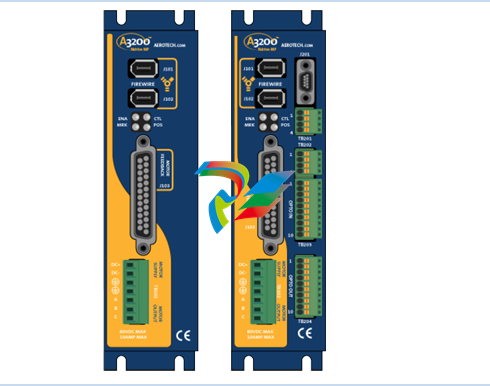 AEROTECH Ndrive MP Hardware Manual
 -
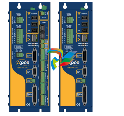 AEROTECH Ndrive HPe 10/20/30
 -
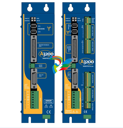 AEROTECH Ndrive CP Hardware Manual
 -
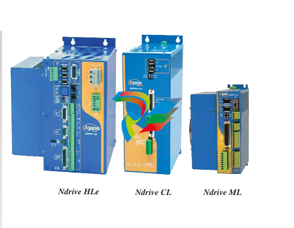 AEROTECH Ndrive Linear Series Digital Servo Amplifiers – Linear
 -
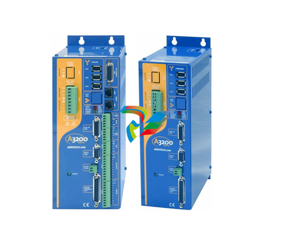 AEROTECH Ndrive HP 10/20/30 P/N: EDU170
 -
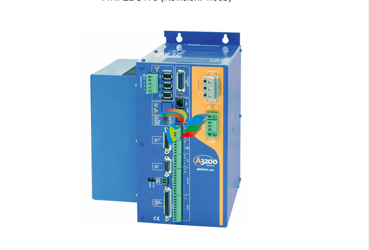 AEROTECH EDU176_Ndrive_HL
 -
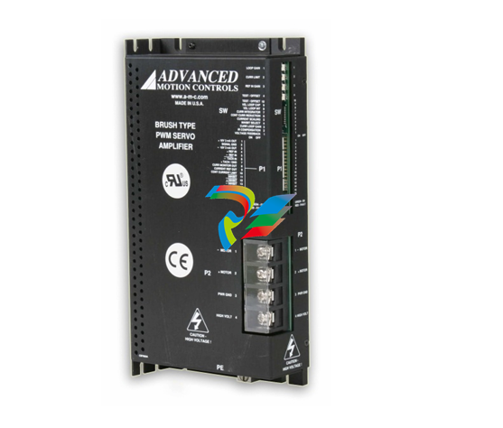 ADVANCEDMOTION CONTROLS Analog Servo Drive 120A10
 -
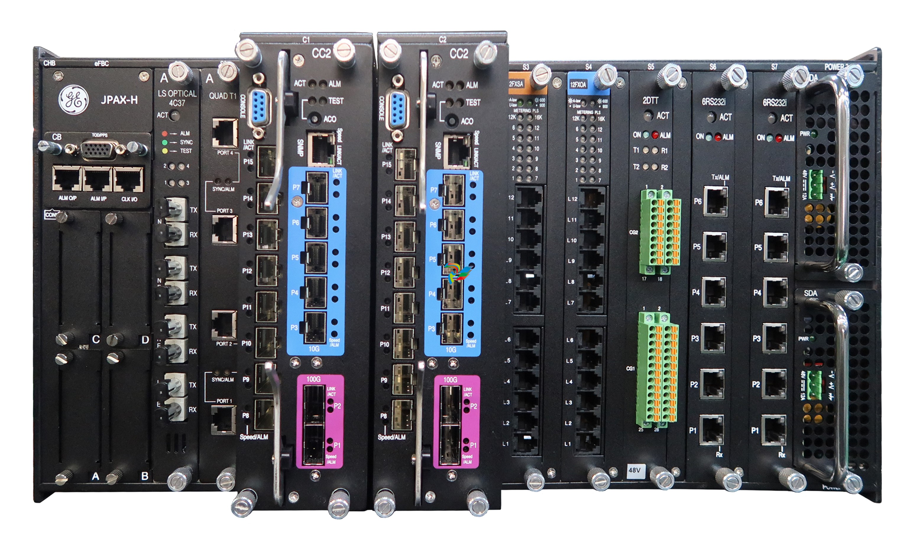 GE JPAX-H
 -
 GE JPAX family
 -
 GE Industry Leading Experience
 -
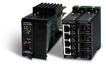 GE Ether-1000 Unit
 -
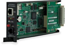 GE Cyber Secured Service Unit
 -
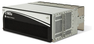 GE Lentronics E1MXe Multiplexer
 -
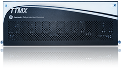 GE TTMX Teleprotection Terminal
 -
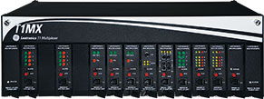 GE Lentronics T1 Multiplexer
 -
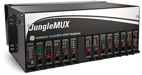 GE Lentronics JungleMUX SONET Multiplexer
 -
 GE Lentronics E1MX Multiplexer
 -
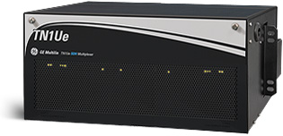
GE Lentronics TN1Ue SDH Multiplexer
-
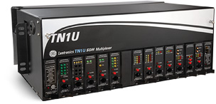 GE Lentronics TN1U SDH Multiplexer
 -
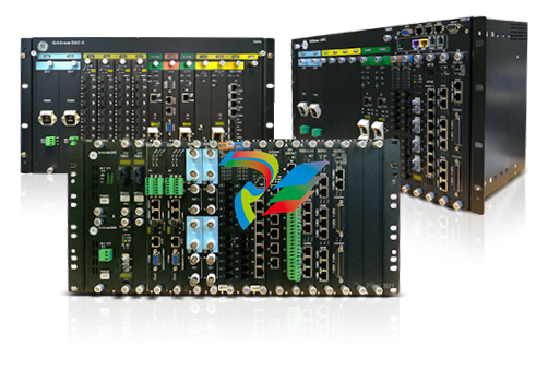 GE Gridcom DXC Family Access and Transmission Multiplexer
 -
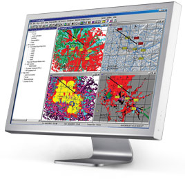
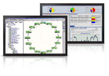 GE Advanced Network Management Simplifying Optical Networks


