
ABB Nextmove ESB-2 motion controller
strap while handling the unit.
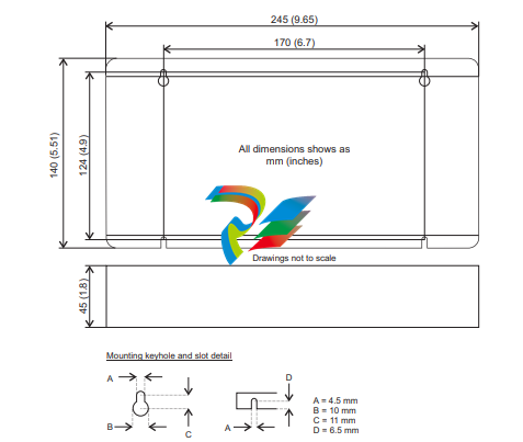
Ensure you have read and understood the location requirements in section 3.1.1. Mount the
NextMove ESB-2 using the supplied M4 screws. For effective cooling, the NextMove ESB-2
must be mounted on a smooth non-flammable vertical surface. Orientation must be as
shown in Figure 1, with the two slots in the metal carrier / heat sink assembly at the bottom.
4.2 Analog I/O The NextMove ESB-2 provides:
Two 12-bit resolution analog inputs.
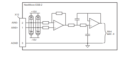
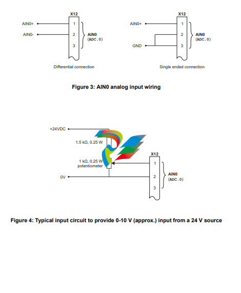
Four 12-bit resolution analog outputs. 4.2.1 Analog inputs The analog inputs are available on connector X12, pins 1 & 2 (AIN0) and 4 & 5 (AIN1). Differential inputs.
Voltage range: ±10 V.
Resolution: 12-bit with sign.
Input impedance: 120 kΩ.
Sampling frequency: 4 kHz maximum, 2 kHz if both inputs are enabled. The analog inputs pass through a differential buffer and second order low-pass filter with a cut-off frequency of approximately 1 kHz. Both inputs are normally sampled at 2 kHz. However, an input can be disabled by setting ADCMODE to 4 (_acOFF). With one input disabled, the remaining input will be sampled at 4 kHz. In Mint, analog inputs can be read using the ADC keyword. See the Mint help file for full details of ADC, ADCMODE and other related ADC... keywords.
4.2.2 Analog outputs
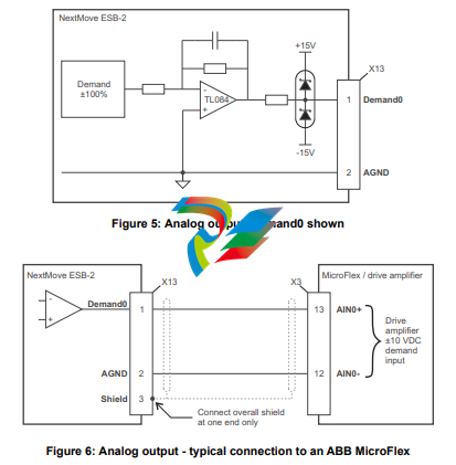
The four analog outputs are available on connector X13, as shown in section 4.1.1.
Four independent bipolar analog outputs.
Output range: ±10 V DC (±0.1%).
Resolution: 12-bit.
Output current: 2.5 mA maximum per output.
Update frequency: 10 kHz maximum (adjustable using the LOOPTIME keyword, factory default 1 kHz).
Mint and the Mint Motion Library use analog outputs Demand0 to Demand3 to control drive amplifiers. Demand outputs 0 to 3 are used by axes configured as servo (see section 5.4.1). A Demand output may be used as a general purpose analog output if it is not assigned to a servo axis - see the DAC keyword in the Mint help file. The analog outputs may be used to drive loads of 4 kΩ or greater. Shielded twisted pair cable should be used. The shield connection should be made at one end only
4.3 Digital I/O
The NextMove ESB-2 provides:
20 general purpose digital inputs.
12 general purpose digital outputs.
4.3.1 Digital inputs
Digital inputs are available on connectors X8, X9 and X10, as shown in section
4.1.1. The digital inputs are arranged in three groups, each with their own common
connection. This allows each group to be configured independently for ‘active high’
or ‘active low’ operation. The general purpose digital inputs DIN0 - DIN19 can be shared
between axes, and are programmable in Mint (using a range of keywords beginning with
the letters INPUT... ) to determine their active level and if they should be edge triggered. The
state of individual inputs can be read directly using the INX keyword. See the Mint help file.
A general purpose digital input can be assigned to a special purpose function such as a home,
limit, stop or error input. See the keywords HOMEINPUT, LIMITFORWARDINPUT, LIMITREVERSEINPUT,
STOPINPUT and ERRORINPUT in the Mint help file.
4.3.1.1 DIN0 - DIN3
Digital inputs DIN0 to DIN3 can be assigned as fast interrupts. These are used as high speed position latches, allowing any combination of axes to be captured by the hardware. The latency between input triggering and capture is 1 μs. Special Mint keywords (beginning with the letters FAST...) allow specific functions to be performed as a result of fast position inputs becoming active. See the Mint help file for details. Digital inputs DIN0 to DIN3 use CREF0 as their common connection.
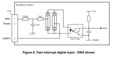
Note: The fast inputs are particularly sensitive to noise, so inputs must use shielded twisted pair cable. Do not connect mechanical switches, relay contacts or other sources liable to signal ‘bounce’ directly to the fast inputs. This could cause unwanted multiple triggering.
4.3.1.2 DIN4 - DIN11 Digital inputs DIN4 to DIN11 have a common specification:
Opto-isolated digital inputs.
Sampling frequency: 1 kHz. Digital inputs DIN4 to DIN11 use CREF1 as their common connection.
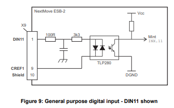
If an input is configured as edge triggered, the triggering pulse must have a duration of at least 1 ms (one software scan) to guarantee acceptance by Mint. The use of shielded cable for inputs is recommended.
4.3.1.3 DIN12 - DIN19.
Digital inputs DIN12 to DIN19 have the same elec
DIN17-DIN19 may also be used as an auxiliary encoder input. DIN17 accepts step (pulse) signals and DIN18 accepts direction signals, allowing an external source to provide the reference for the speed and direction of an axis. The step frequency (15 kHz maximum) determines the speed, and the direction input determines the direction of motion. Both the rising and falling edges of the signal on DIN17 cause an internal counter to be changed; see Figure 11. If 5 V is applied to DIN18 (or it is left unconnected) the counter will increment. If DIN18 is grounded the counter will be decremented. A minimum period of 500 µs is required between transitions on the direction and step input to guarantee the change of direction has been recognized. Typically, one channel of an encoder signal (either A or B) is used to provide the step signal on DIN17, allowing the input to be used as an auxiliary (master) encoder input. The input can be used as a master position reference for cam, fly and follow move types. For this, the MASTERSOURCE keyword must be used to configure the step input as a master (auxiliary) encoder input. The master position reference can then be read with the AUXENCODER keyword (using 0 as the channel parameter). Since a secondary encoder channel is not used, DIN18 allows the direction of motion to be determined. The Z signal on DIN19 can be supplied from the encoder's index signal, and may be read using the AUXENCODERZLATCH keyword. See the Mint help file for details of each AUXENCODER... keyword.
-
 Rolls-Royce PCC1030C Panel Controller Card
 -
 Rolls-Royce RRDIO15 Remote Digital Input/Output Module
 -
 Rolls-Royce TDI-11 Pitch & Direction Indicator Module
 -
 Rolls-Royce CCN 01 CANman Controller Network Module
 -
 Rolls-Royce SLIO 01 CANman Controller Network Module
 -
 Rolls-Royce MPC-210 Winch & Propulsion Control Module
 -
 Rolls-Royce MTI-144 Engine Control Module
 -
 Rolls-Royce Tenfjord FB10-002 Steering Gear Module (E-4500-40-1)
 -
 ROLLS ROYCE MARINE AS CIRCUIT BOARD (PCB) RRAI016
 -
 Rolls-Royce Marine AS PIP6-1 Marine Controller
 -
 ROLLS-ROYCE MPC-300 STARTER CONTROL UNIT A7029099
 -
 Rolls-Royce Data Respons MPCF1-10.4" Maritime Panel Computer
 -
 ROLLS-ROYCE MARINE OLC-40009 PCB CARD
 -
Rolls-Royce Marine Brattvaag WRC1021B Controller Board
-
 ROLLS-ROYCE CCN 01 & ROLLS-ROYCE SLIO 02 CANMAN CONTROLLER NETWORK
 -
.png) ROLLS-ROYCE ATC-3-A7033172 AQUAMASTER TURNING CONTROLLER
ROLLS-ROYCE ATC-3-A7033172 AQUAMASTER TURNING CONTROLLER -
 ROLLS-ROYCE POSCON V.3 JOYSTICK MODULE 6459
 -
.png) Rolls-Royce Marine 389-496-00 Joystick Remote Control Panel 6799-W, 389-996-00
Rolls-Royce Marine 389-496-00 Joystick Remote Control Panel 6799-W, 389-996-00 -
 Rolls-Royce data respons 10.4'' Panel Computer 98H010A0000I/R10I53S
 -
 Rolls-Royce H1127.0101 Marine Controller 000068308
 -
 Rolls-Royce CU40-0106-50 Steering Gear Control Panel
 -
 Beckhoff Polaris CP7011-1002-0010 operator operator HMI display 30.5 cm
 -
 Beckhoff AM8052-0JH1-0000 Servomotor 10.7 Nm (M0), F5 (104 mm)
 -
 Beckhoff BX5100-0000 CANopen Bus Terminal Controller
 -
 Beckhoff CX9020-0115 PLC Module CX90200115
 -
 Beckhoff module EJ7211-0010 EtherCAT plug-in module
 -
 BECKHOFF AX5203-0000 Servo Driver
 -
 BECKHOFF CP6201-0001-0020 24VDC UNMP
 -
 Beckhoff CX5120-0135 Embedded PC CPU Module
 -
 BECKHOFF C5240-0020/000224115 Plc Module
 -
 Beckhoff CP2918-0000 nelCP29xx-0000Pa | Multi-touch built-in Control Panel with DVI/USB Extended interface
 -
 Beckhoff CX2020-0122 Embedded PC Controller
 -
 Beckhoff C6640-0040 Control Cabinet Industrial PC 7-Slot
 -
 BECKHOFF CONTROL CABINET INDUSTRIAL PC - C6930-1062-0050
 -
 Beckhoff Automation EtherCAT Terminal EK1100 EK1122
 -
Beckhoff CP6533-0001-0060 IPC
-
 Beckhoff EK9500 | EtherNet/IP™ Bus Coupler
 -
 Beckhoff CP6202-1047-0050 - An industrial-grade embedded panel computer.
 -
 Beckhoff C6650-0040 Industrial PC
 -
 BECKHOFF CX5230-0185 / 000119805 PLC Module
 -
 BECKHOFF EL4732 | EtherCAT Terminal, 2-channel analog output, voltage, ±10 V, 16 bit, oversampling
 -
 Beckhoff CP6202-0001-0010 Economy Built-In Panel
 -
 Beckhoff AX5206-0000-0202 Digital Compact Servo Drives 2-channel
 -
 Beckhoff CP6606-0001-0020 7-inch Economy Panel PC
 -
 Beckhoff CPU basic module CX2020-0155 + power supply module CX2100-0004
 -
 Beckhoff CP2913-000 Multi-Touch Display
 -
 Beckhoff CP6500-1012-0060 14250369 Control Cabinet
 -
 Beckhoff CP7902-0001-0000 Economy Control Panel with DVI/USB Extended interface
 -
 Beckhoff C6920-0010 Control cabinet Industrial PC
 -
 BECKHOFF C3640-0050 Build-in Industrial PCs
 -
 Beckhoff KL6023-0000 KL6023 EnOcean Wireless-Adapter
 -
 Kollmorgen AKM54G-ANC2DB00 servo motor
 -
 Kollmorgen AKD-P00606-NBCN-0000 Servo Drive
 -
Kollmorgen S200 Series S20350-VTS SERVO DRIVE
-
 KOLLMORGEN AKD-P00606-NBCC-I000 SERVO DRIVE
 -
 Kollmorgen MV65WKS-CE310/22PB Servo Drive Control Module
 -
 Kollmorgen S20360-VTS-021 Servo Drive
 -
 KOLLMORGEN CR06550 High-precision digital servo amplifier
 -
 KOLLMORGEN DBL5N01050-03S-VV0-S40 3-Phase AC Synchronous Brushless Servo Motor
 -
 KOLLMORGEN S70301-NANANA-024 SERVO DRIVE
 -
 Kollmorgen S20360-VTS S200 Series Servo Drive
 -
 Kollmorgen RBE-03011-A00 Brushless Frameless Servo Motor
 -
 KOLLMORGEN AKD-T00306-NBAN-0000 INPUT SERVO DRIVE
 -
 KOLLMORGEN S700 Servo Controller S70302-NANANA
 -
 Kollmorgen AKD-P00607-NBEC-0000 400/480VAC 4.40KVA Servo Drive.
 -
 KOLLMORGEN S70102-NANANA SERVO DRIVE
 -
 KOLLMORGEN AKM21E-ANSNEH02 PM Servo Motor & PRD-AMPE25EB-00 Servo Drive Array
 -
 KollMorgen SC1R06260 Servo Drive 1.4/2.2 KVA 115230 Vac
 -
 Kollmorgen AKD-P00306-NBAN-0000 Servo Drive
 -
Kollmorgen TTB2-2042-3052-A DC Motor Industrial Drive 5.5A 185 oz/in
-
 KOLLMORGEN SERVOSTAR 610-AS SERVO AMPLIFIER_SERVOSTAR610AS_S61001
 -
 KOLLMORGEN PRD-0016400P-10 & PRD-0016600D-30 Axis Control System Modules
 -
KOLLMORGEN Seidel DBL5N01700-03S-000-S40 Servo Motor
-
 Hirschmann RS20-1600M2T1SDAEHH03.1.02 Rail Switch
 -
 Hirschmann BRS30-24TX Industrial Rail Switch
 -
 Hirschmann RSPM20-4T14T1EV9HHS999.9.99 Managed Ethernet Switch
 -
 Hirschmann BELDEN RS40-0009CCCCSDAPHH09.0.14 / RS400009CCCCSDAPHH09014
 -
Hirschmann RS40 Rail Switch RS40-0009CCCCSDAE
-
 Hirschmann BELDEN RS30-0802T1T1SDAP / RS300802T1T1SDAP Fully Managed Layer 2 Compact Rail Switch
 -
 Hirschmann BELDEN RS20-0800M2M2SDAUHH / RS200800M2M2SDAUHH
 -
 Hirschmann EAGLE30-04022O6TT999SCCY9HSE3F Industrial Firewall Router Switch
 -
 Hirschmann RS20-1600T1T1SDAEHH09.0.14 RS20 Rail Mount Ethernet Switch
 -
 Hirschmann EAGLE0200T1T1TDDY90000HHE05.3.03 Industrial Security Router
 -
Hirschmann - BELDEN MIPP-AD-1L9P
-
 HIRSCHMANN RSPM20-4Z64Z6TV9HHS9 942 106-999 RAIL SAFETY SWITCH
 -
 HIRSCHMANN FIBEROPTIC MODULE FIP P/N: OZDFIPG3T
 -
 HIRSCHMANN RS20-1600M2M2SDAUHH Ethernet rack-mounted switch
 -
 HIRSCHMANN BELDEN RS20-0400T1T1SDAEHH04.0.01 / RS200400T1T1SDAEHH04001
 -
HIRSCHMANN MM2-4FXM3 MICE Media Module
-
HIRSCHMANN RS20-0800M2M2SDAE Industrial Ethernet Rail Switch
-
 Hirschmann RS20-2400T1T1SDAP / RS20-2400T1T1SDAPHH05.0.02
 -
 GE MLJ1005B010H00C MLJ Digital Synchromism Check
 -
 ALSTOM MICROTECH DX21-M2 Digital Excitation Controller
 -
HIRSCHMANN BRS20-1200ZZZZ-STCY99HHSES
-
 HIRSCHMANN MM3-4FXM2 MICE Media Module
 -
Hirschmann RSB20-0800T1T1SAABHH 8Port ENet Rail Switch RSB20
-
 Hirschmann MACH102-8TP Ethernet Switch
 -
 SAACKE DDZ-M marine steam pressure atomizer
 -
 SAACKE SKV-A marine rotary cup atomizer
 -
 SAACKE Seavis HMI05e
 -
 Kollmorgen MMC-SD-2.0-230 Servo Drive 100-240VAC 2KW 10A Output 3PH 100-240VAC
 -
 Kollmorgen Servo drive CR10550
 -
 Kollmorgen AKD-P01207-NACN-0054 Servo Driver
 -
 Kollmorgen S406M-CA-036 Servostar
 -
.png) Kollmorgen AKD-B02407-NAAN-0000 Digital Servo Drive
Kollmorgen AKD-B02407-NAAN-0000 Digital Servo Drive -
 Kollmorgen SERVOSTAR S406AM-CA Digital Servo Drive
 -
 KOLLMORGEN SERVOSTAR 603-AS SERVO AMPLIFIER_SERVOSTAR603AS_S60301
 -
Kollmorgen S700 Servo Controller (S70602-NANANA-NA)
-
 Kollmorgen MPK411 controller
 -
 KOLLMORGEN MMC-SD-1.3-460-D Smart Drive
 -
 KOLLMORGEN AKM21C-CKB2AA-00 / AKM21CCKB2AA00 Servomotor
 -
 BECKHOFF AX5106-0000-0200 | Digital Compact Servo Drives 1-channel
 -
 BECKHOFF C3620-0000 INDUSTRIAL COMPUTER (MOTORSHELVES)
 -
 Beckhoff EK1960-0000 TwinSAFE Compact Controller
 -
 Beckhoff C6930-0050 Control Cabinet Industrial PC
 -
 Beckhoff CP7711-0001-0030 Industrial Computer Detection
 -
 Beckhoff CX1001-0111 Embedded PC CPU Module
 -
 Beckhoff C6017-0020 | Ultra-compact Industrial PC
 -
 Beckhoff EK1322 | 2-port EtherCAT P junction with feed-in
 -
 Beckhoff CP2219-0010 Panel
 -
 BECKHOFF C6015-0020 ULTRA COMPACT INDUSTRIAL PC
 -
 BECKHOFF CX2030-0120/Standard CPU Module Embedded PC Windows PLC controller
 -
 Beckhoff CP7721-1090-0020 Panel PC
 -
 Beckhoff PC CPU Module CX5130-0175
 -
 Beckhoff C6920-0050 Control Cabinet
 -
 Beckhoff EL6631 EtherCAT 2-Port Communication Interface, Profinet RT Controller
 -
 Beckhoff CP6202-0001-0060 touch screen panel PC
 -
 Beckhoff CP3916-1002-0000 Multi-Touch Control Panel


