
ABB Nextmove ESB-2 motion controller
Safety Notice
Only qualified personnel should attempt to start-up, program or troubleshoot this equipment. This
equipment may be connected to other machines that have rotating parts or parts that are controlled
by this equipment. Improper use can cause serious or fatal injury
Precautions

Do not touch any circuit board, power device or electrical connection before you first ensure that no high voltage is present at this equipment or other equipment to which it is connected. Electrical shock can cause serious or fatal injury. Only qualified personnel should attempt to start-up, program or troubleshoot this equipment.
Be sure that you are completely familiar with the safe operation and programming of this equipment. This equipment may be connected to other machines that have rotating parts or parts that are controlled by this equipment. Improper use can cause serious or fatal injury.
MEDICAL DEVICE / PACEMAKER DANGER: Magnetic and electromagnetic fields in the vicinity of current carrying conductors and industrial motors can result in a serious health hazard to persons with cardiac pacemakers, internal cardiac defibrillators, neurostimulators, metal implants, cochlear implants, hearing aids, and other medical devices. To avoid risk, stay away from the area surrounding a motor and its current carrying conductors.
The stop input to this equipment should not be used as the single means of achieving a safety critical stop. Drive disable, motor disconnect, motor brake and other means should be used as appropriate
Improper operation or programming may cause violent motion of the motor shaft and driven equipment. Be certain that unexpected motor shaft movement will not cause injury to personnel or damage to equipment. Peak torque of several times the rated motor torque can occur during control failure.
The safe integration of this equipment into a machine system is the responsibility of the machine designer. Be sure to comply with the local safety requirements at the place where the machine is to be used. In Europe these are the Machinery Directive, the ElectroMagnetic Compatibility Directive and the Low Voltage Directive. In the United States this is the National Electrical code and local codes.
Electrical components can be damaged by static electricity. Use ESD (electrostatic discharge) procedures when handling this equipment.
NextMove ESB-2 features
NextMove ESB-2 is a high performance multi-axis intelligent controller for servo and steppermotors.
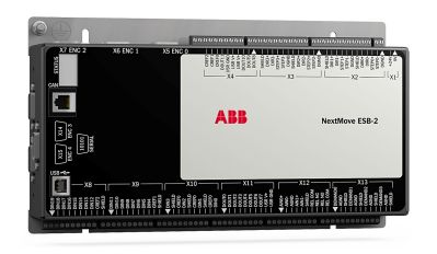
NextMove ESB-2 features the Mint motion control language. Mint is a structured form of Basic, custom designed for stepper or servo motion control applications. It allows you to get started very quickly with simple motion control programs. In addition, Mint includes a wide range of powerful commands for complex applications. Standard features include:
Control of 4 stepper axes and either 3 or 4 servo axes (model dependent). Additional encoder input for master follower applications. A wide variety of motion types including point to point moves, software cams and gearing. 20 general purpose digital inputs, software configurable as level or edge triggered. 12 general purpose digital outputs. 2 differential analog inputs with 12-bit resolution. 4 single-ended analog outputs with 12-bit resolution. USB 1.1 serial port (compatible with USB 2.0 and USB 3.0). CANopen protocol for communication with Mint controllers and other third party CANopen devices. Programmable in Mint. Drop-in replacement for NextMove ESB.
2.2.1 Identifying the catalog number
Different models of NextMove ESB-2 are available. As a reminder of which product has been installed, it is a good idea to write the catalog number in the space provided below.
To prevent equipment damage, be certain that input and output signals are
powered and referenced correctly.
To ensure reliable performance of this equipment be certain that all signals to/
from the NextMove ESB-2 are shielded correctly.
Avoid locating the NextMove ESB-2 immediately above or beside heat
generating equipment, or directly below water steam pipes.
Avoid locating the NextMove ESB-2 in the vicinity of corrosive substances or
vapors, metal particles and dust.
The safe operation of this equipment depends upon its use in the appropriate environment.
The following points must be considered:
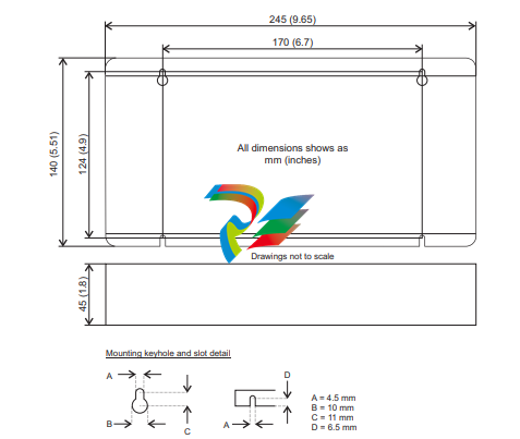
The NextMove ESB-2 is designed to be mounted indoors, permanently fixed and
located.
The NextMove ESB-2 must be secured by the slots in the metal case.
The NextMove ESB-2 must be installed in an ambient temperature of 0 °C to 45 °C
(32 °F to 113 °F).
The NextMove ESB-2 must be installed in relative humidity levels of less than 80% for
temperatures up to 31 °C (87 °F) decreasing linearly to 50% relative humidity at 45 °C
(113 °F), non-condensing.
The NextMove ESB-2 must be installed where the pollution degree according to IEC
60664-1 shall not exceed 2.
There shall not be abnormal levels of nuclear radiation or X-rays.
Before touching the unit be sure to discharge static electricity from your body
and clothing by touching a grounded metal surface. Alternatively, wear an earth
strap while handling the unit.
Ensure you have read and understood the location requirements in section 3.1.1. Mount the
NextMove ESB-2 using the supplied M4 screws. For effective cooling, the NextMove ESB-2
must be mounted on a smooth non-flammable vertical surface. Orientation must be as
shown in Figure 1, with the two slots in the metal carrier / heat sink assembly at the bottom.
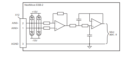
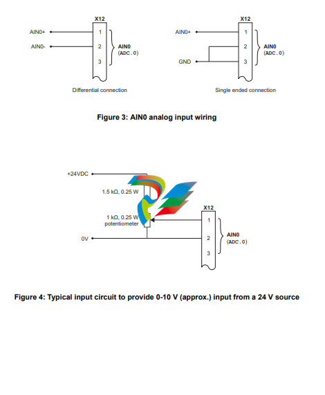
4.2 Analog I/O The NextMove ESB-2 provides:
Two 12-bit resolution analog inputs.
Four 12-bit resolution analog outputs. 4.2.1 Analog inputs The analog inputs are available on connector X12, pins 1 & 2 (AIN0) and 4 & 5 (AIN1). Differential inputs.
Voltage range: ±10 V.
Resolution: 12-bit with sign.
Input impedance: 120 kΩ.
Sampling frequency: 4 kHz maximum, 2 kHz if both inputs are enabled. The analog inputs pass through a differential buffer and second order low-pass filter with a cut-off frequency of approximately 1 kHz. Both inputs are normally sampled at 2 kHz. However, an input can be disabled by setting ADCMODE to 4 (_acOFF). With one input disabled, the remaining input will be sampled at 4 kHz. In Mint, analog inputs can be read using the ADC keyword. See the Mint help file for full details of ADC, ADCMODE and other related ADC... keywords.
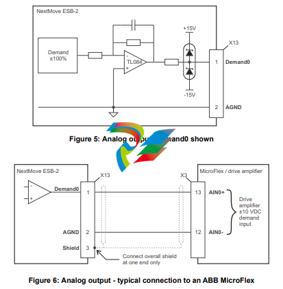
4.2.2 Analog outputs
The four analog outputs are available on connector X13, as shown in section 4.1.1.
Four independent bipolar analog outputs.
Output range: ±10 V DC (±0.1%).
Resolution: 12-bit.
Output current: 2.5 mA maximum per output.
Update frequency: 10 kHz maximum (adjustable using the LOOPTIME keyword, factory
default 1 kHz).
Mint and the Mint Motion Library use analog outputs Demand0 to Demand3 to control drive amplifiers. Demand outputs 0 to 3 are used by axes configured as servo (see section 5.4.1). A Demand output may be used as a general purpose analog output if it is not assigned to a servo axis - see the DAC keyword in the Mint help file. The analog outputs may be used to drive loads of 4 kΩ or greater. Shielded twisted pair cable should be used. The shield connection should be made at one end only
4.3 Digital I/O
The NextMove ESB-2 provides:
20 general purpose digital inputs.
12 general purpose digital outputs.
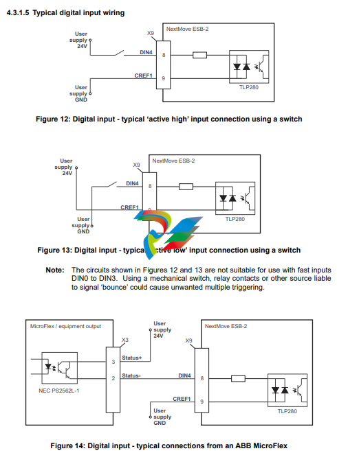
4.3.1 Digital inputs
Digital inputs are available on connectors X8, X9 and X10, as shown in section
4.1.1. The digital inputs are arranged in three groups, each with their own common
connection. This allows each group to be configured independently for ‘active high’
or ‘active low’ operation. The general purpose digital inputs DIN0 - DIN19 can be shared
between axes, and are programmable in Mint (using a range of keywords beginning with
the letters INPUT... ) to determine their active level and if they should be edge triggered. The
state of individual inputs can be read directly using the INX keyword. See the Mint help file.
A general purpose digital input can be assigned to a special purpose function such as a home,
limit, stop or error input. See the keywords HOMEINPUT, LIMITFORWARDINPUT, LIMITREVERSEINPUT,
STOPINPUT and ERRORINPUT in the Mint help file.
4.3.1.1 DIN0 - DIN3
Digital inputs DIN0 to DIN3 can be assigned as fast interrupts. These are used as high speed position latches, allowing any combination of axes to be captured by the hardware. The latency between input triggering and capture is 1 μs. Special Mint keywords (beginning with the letters FAST...) allow specific functions to be performed as a result of fast position inputs becoming active. See the Mint help file for details. Digital inputs DIN0 to DIN3 use CREF0 as their common connection.
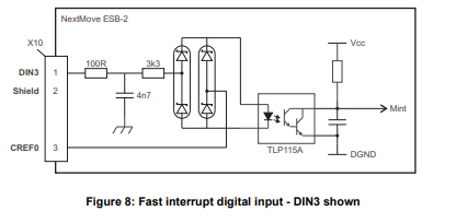
Note: The fast inputs are particularly sensitive to noise, so inputs must use shielded twisted pair cable. Do not connect mechanical switches, relay contacts or other sources liable to signal ‘bounce’ directly to the fast inputs. This could cause unwanted multiple triggering.
4.3.1.2 DIN4 - DIN11
Digital inputs DIN4 to DIN11 have a common specification:
Opto-isolated digital inputs.
Sampling frequency: 1 kHz.
Digital inputs DIN4 to DIN11 use CREF1 as their common connection.
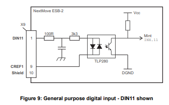
If an input is configured as edge triggered, the triggering pulse must have a duration of at least 1 ms (one software scan) to guarantee acceptance by Mint. The use of shielded cable for inputs is recommended.
4.3.1.3 DIN12 - DIN19.
Digital inputs DIN12 to DIN19 have the same elec
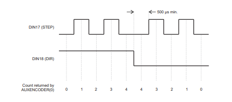
DIN17-DIN19 may also be used as an auxiliary encoder input. DIN17 accepts step (pulse)
signals and DIN18 accepts direction signals, allowing an external source to provide the
reference for the speed and direction of an axis. The step frequency (15 kHz maximum)
determines the speed, and the direction input determines the direction of motion. Both the
rising and falling edges of the signal on DIN17 cause an internal counter to be changed; see
Figure 11. If 5 V is applied to DIN18 (or it is left unconnected) the counter will increment. If
DIN18 is grounded the counter will be decremented. A minimum period of 500 µs is required
between transitions on the direction and step input to guarantee the change of direction has
been recognized.
Typically, one channel of an encoder signal (either A or B) is used to provide the step signal
on DIN17, allowing the input to be used as an auxiliary (master) encoder input. The input can
be used as a master position reference for cam, fly and follow move types. For this, the
MASTERSOURCE keyword must be used to configure the step input as a master (auxiliary)
encoder input. The master position reference can then be read with the AUXENCODER
keyword (using 0 as the channel parameter). Since a secondary encoder channel is not
used, DIN18 allows the direction of motion to be determined. The Z signal on DIN19 can be
supplied from the encoder's index signal, and may be read using the AUXENCODERZLATCH
keyword. See the Mint help file for details of each AUXENCODER... keyword.
Note that encoder input ENC 4 forms another auxiliary encoder input, using normal incremental encoder connections A, B and Z. This supports a higher frequency input and additional functionality - see section 4.4.3
4.4 Other I/O
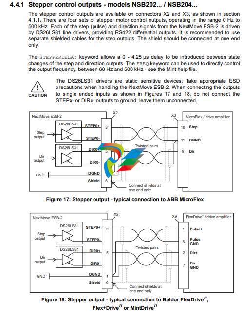
4.4.1 Stepper control outputs - models NSB202... / NSB204...
The stepper control outputs are available on connectors X2 and X3, as shown in section
4.1.1. There are four sets of stepper motor control outputs, operating in the range 0 Hz to
500 kHz. Each of the step (pulse) and direction signals from the NextMove ESB-2 is driven
by DS26LS31 line drivers, providing RS422 differential outputs. It is recommended to use
separate shielded cables for the step outputs. The shield should be connected at one end
only.
The STEPPERDELAY keyword allows a 0 - 4.25 μs delay to be introduced between state
changes of the step and direction outputs. The FREQ keyword can be used to directly control
the output frequency, between 60 Hz and 500 kHz - see the Mint help file.
The DS26LS31 drivers are static sensitive devices. Take appropriate ESD
precautions when handling the NextMove ESB-2. When connecting the outputs
to single ended inputs as shown in Figures 17 and 18, do not connect the
STEPx- or DIRx- outputs to ground; leave them unconnected.
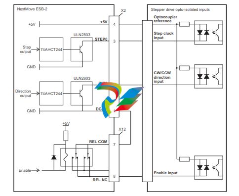
4.4.2 Stepper control outputs - models NSB203... / NSB205...
The stepper control outputs are available on connectors X2 and X3, as shown in section 4.1.1. There are four sets of stepper motor control outputs, operating in the range 0 Hz to 500 kHz. Each of the step (pulse) and direction signals from the NextMove ESB-2 is driven by a ULN2803 open collector Darlington output device. The STEPPERDELAY keyword allows a 0 - 4.25 μs delay to be introduced between state changes of the step and direction outputs. The FREQ keyword can be used to directly control the output frequency, between 60 Hz and 500 kHz - see the Mint help file.
The ULN2803 drivers are static sensitive devices. Take appropriate ESD precautions when handling the NextMove ESB-2. A 5 V, 600 mA supply is provided on connectors X2 and X3 for powering external circuits, as shown in Figure 19. The same 5 V supply is also present on connectors X5, X6, X7, X14 and X15 for powering encoders. Ensure that the total combined current demand of all 5 V outputs does not exceed 1.8 A. It is usually necessary to connect a 470 Ω pull-up resistor between the output and the 5 V supply (pin 4), especially where induced noise is affecting a step or direction output.
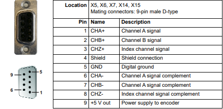
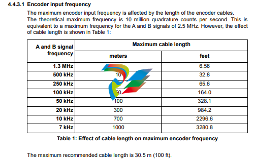
Five incremental encoders may be connected to NextMove ESB-2, each with complementary A, B and Z channel inputs. Each input channel uses a MAX3095 differential line receiver with pull up resistors and terminators. Encoders must provide RS422 differential signals. The use of individually shielded twisted pair cable is recommended. A 5 V (±5%), 250 mA supply is provided on each connector for powering the encoder. The same 5 V supply is also present on connectors X2 and X3 for powering external circuits (see sections 4.4.1 and 4.4.2). Ensure that the total combined current demand of all 5 V outputs does not exceed 1.85 A.
Encoder inputs ENC 0 - ENC 3 can be read and controlled with a range of Mint keywords
beginning with ENCODER... . When using these keywords, the encoder’s number is used
as the channel parameter. For example, Print ENCODER(2) reads the ENC 2 input.
Encoder input ENC 4 can be read and controlled with a range of Mint keywords
beginning with AUXENCODER... . When its position has been latched by a fast interrupt
(see section 4.3.1.1) it can also be controlled using Mint keywords beginning with
FASTAUX... . When using the AUXENCODER... or FASTAUX... keywords, the channel
parameter 1 is used (i.e. auxiliary encoder channel 1). For example,
Print FASTAUXENCODER(1) reads the latched value read from ENC 4. Note that
auxiliary encoder channel 0 is used to reference the auxiliary encoder input formed by
digital inputs DIN17 - DIN19 (see section 4.3.1.4).
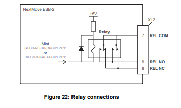
Relay connections
The relay connections are available on connector X12, as shown in section 4.1.1. The relay
outputs are isolated from any internal circuits in the NextMove ESB-2. In normal operation,
while there is no error, the relay is energized and REL COM is connected to REL NO. In the
event of an error or power loss, the relay is de-energized, and REL COM is connected to
REL NC. The relay can be controlled by the RELAY keyword, and can be configured as the
global error output by setting GLOBALERROROUTPUT to 1000 (_RELAY0). See the Mint help
file
USB port
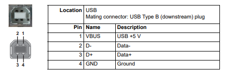
The USB connector can be used as an alternative method for connecting the NextMove ESB-2 to a PC running Mint WorkBench. The NextMove ESB-2 is a self-powered, USB 1.1 (12 Mbps) compatible device. If it is connected to a slower USB 1.0 host PC or hub, communication speed will be limited to the USB 1.0 specification (1.5 Mbps). If it is connected to a faster USB 2.0 (480 Mbps) or USB 3.0 (5 Gbps) host PC or hub, communication speed will remain at the USB 1.1 specification of the NextMove ESB-2. Ideally, the NextMove ESB-2 should be connected directly to a USB port on the host PC. If it is connected to a hub shared by other USB devices, communication could be affected by the activity of the other devices. The maximum recommended cable length is 5 m (16.4 ft).
Serial port
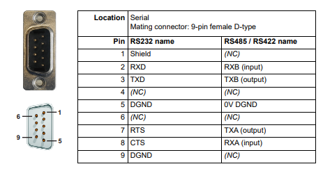
NextMove ESB-2 is available with either an RS232 or RS485 serial port (see section 2.2.1). The port is fully ESD protected to IEC 1000-4-2 (15 kV). When the NextMove ESB-2 is connected to Mint WorkBench, the Tools, Options menu item can be used to configure the serial port. The configuration can also be changed using the Mint keyword SERIALBAUD (see the Mint help file for details). It is stored in EEPROM and restored at power up. The port is capable of operation at up to 115.2 Kbaud on RS232.
Using RS232
The NextMove ESB-2 has a full-duplex RS232 serial port with the following preset configuration:
57.6 Kbaud
1 start bit
8 data bits
1 stop bit
No parity
Hardware handshaking lines RTS and CTS must be connected.
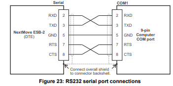
The RS232 port is configured as a DCE (Data Communications Equipment) unit so it is possible to operate the controller with any DCE or DTE (Data Terminal Equipment). Full duplex transmission with hardware handshaking is supported. Only the TXD, RXD and 0V GND connections are required for communication, but since many devices will check the RTS and CTS lines, these must also be connected. Pins 4 and 6 are linked on the NextMove ESB-2. The maximum recommended cable length is 3 m (10 ft) at 57.6 Kbaud (the factory preset rate). When using lower baud rates, longer cable lengths may be used up to maximum of 15 m (49 ft) at 9600 baud.
Multidrop using RS485 / RS422
Multidrop systems allow one device to act as a ‘network master’, controlling and interacting with the other (slave) devices on the network. The network master can be a controller such as NextMove ESB-2, a host application such as Mint WorkBench (or other custom application), or a programmable logic controller (PLC). RS422 may be used for multi-drop applications as shown in Figure 24. Four-wire RS485 may be used for single point-to-point applications involving only one controller. If firmware is updated over RS485/RS422, it can only be downloaded to the controller that was chosen in the Select Controller dialog in Mint WorkBench.
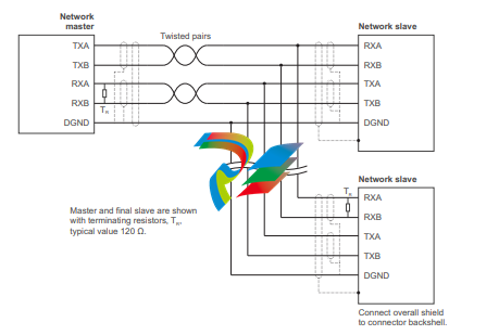
Figure 24: 4-wire RS422 multi-drop connections
Each transmit/receive (TX/RX) network requires a termination resistor at the final RX
connection, but intermediate devices must not be fitted with termination resistors. An
exception is where repeaters are being used which may correctly contain termination
resistors. Termination resistors are used to match the impedance of the load to the
impedance of the transmission line (cable) being used. Unmatched impedance causes the
transmitted signal to not be fully absorbed by the load. This causes a portion of the signal to
be reflected back into the transmission line as noise. If the source impedance, transmission
line impedance, and load impedance are all equal, the reflections (noise) are eliminated.
Termination resistors increase the load current and sometimes change the bias requirements
and increase the complexity of the system
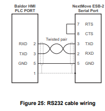
Connecting serial Baldor HMI Operator Panels
Serial Baldor HMI Operator Panels use a 15-pin male D-type connector (marked PLC
PORT), but the NextMove ESB-2 Serial connector uses a 9-pin male D-type connector. The
NextMove ESB-2 may be connected as shown in Figure 25:
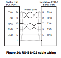
Alternatively, the Baldor HMI panel may be connected using RS485/422, as shown in Figure 26:
CAN
The CAN bus is a serial based network originally developed for automotive applications, but
now used for a wide range of industrial applications. It offers low-cost serial communications
with very high reliability in an industrial environment; the probability of an undetected error is
4.7x10⁻¹¹. It is optimized for the transmission of small data packets and therefore offers fast
update of I/O devices (peripheral devices) connected to the bus.
The CAN protocol only defines the physical attributes of the network, i.e. the electrical,
mechanical, functional and procedural parameters of the physical connection between
devices. The higher level network functionality on NextMove ESB-2 is defined by the
CANopen protocol, one of the most used standards for machine control.
In addition to supporting CANopen, Baldor has developed a proprietary protocol called
Baldor CAN. Both protocols are supported by NextMove ESB-2, but not at the same time.
This is because NextMove ESB-2 only has a single hardware CAN channel. Separate
firmware builds are available to support each of the protocols.
To determine which firmware is currently installed, start Mint WorkBench and connect to the
NextMove ESB-2 (see section 5.3.2). At the bottom of the Mint WorkBench window, the
status bar will show the name of the controller, followed by ‘CANopen’ or ‘Baldor CAN’. If the
correct option is not shown, it will be necessary to download alternative firmware by using the
Install System File and/or Download Firmware menu items in Mint WorkBench. The firmware
can be downloaded from www.abbmotion.com or, in Mint WorkBench, by using the Help, On
The Web, Firmware Updates menu option. See the Mint help file for details about
downloading firmware.
CAN connector
The CAN connection is made using the RJ45 connector on the NextMove ESB-2.

CAN wiring
A very low error bit rate over CAN can only be achieved with a suitable wiring scheme, so the
following points should be observed:
The two-wire data bus line may be routed parallel, twisted and/or shielded, depending on EMC requirements. ABB recommends a twisted pair cable with the shield/screen connected to the connector backshell, in order to reduce RF emissions and provide immunity to conducted interference. The bus must be terminated at both ends only (not at intermediate points) with resistors of a nominal value of 120 Ω. This is to reduce reflections of the electrical signals on the bus, which helps a node to interpret the bus voltage levels correctly. If the NextMove ESB-2 is at the end of the network then ensure that jumper JP1, located just behind the status display, is in position. This will connect an internal terminating resistor. To access the jumper it will be necessary to remove the top cover from the NextMove ESB-2. Before removing the top cover be sure to discharge static electricity from your body and clothing by touching a grounded metal surface. Alternatively, wear an earth strap while handling the unit. All cables and connectors should have a nominal impedance of 120 Ω. Cables should have a length related resistance of 70 mΩ/m and a nominal line delay of 5 ns/m. A range of suitable CAN cables are available from ABB, with part numbers beginning CBL004-5... . The maximum bus length depends on the bit-timing configuration (baud rate). The table opposite shows the approximate maximum bus length (worst-case), assuming 5 ns/m propagation delay and a total effective device internal in-out delay of 210 ns at 1 Mbit/s, 300 ns at 500 - 250 Kbit/s, 450 ns at 125 Kbit/s and 1.5 ms at 50 - 10 Kbit/s. (1) CAN baud rate not supported on Baldor CAN. (2) For bus lengths greater than about 1000 m, bridge or repeater devices may be needed. The compromise between bus length and CAN baud rate must be determined for each application. The CAN baud rate can be set using the BUSBAUD keyword. It is essential that all nodes on the network are configured to run at the same baud rate. The wiring topology of a CAN network should be as close as possible to a single line/bus structure. However, stub lines are allowed provided they are kept to a minimum (<0.3 m at 1 Mbit/s). The 0 V connection of all of the nodes on the network must be tied together through the CAN cabling. This ensures that the CAN signal levels transmitted by NextMove ESB-2 or CAN peripheral devices are within the common mode range of the receiver circuitry of other nodes on the network.
CANopen
The NextMove ESB-2 must have the CANopen firmware loaded to use this protocol
ABB has implemented a CANopen protocol in Mint (based on the ‘Communication Profile’ CiA DS-301) which supports both direct access to device parameters and time-critical process data communication. The NextMove ESB-2 design does not comply with a specific CANopen device profile (DS4xx), although it is able to support and communicate with the following devices:
Any third party digital and analog I/O device that is compliant with the ‘Device Profile for Generic I/O Modules’ (CiA DS-401). Baldor HMI (Human Machine Interface) operator panels, which are based on the ‘Device Profile for Human Machine Interfaces’ (DS403). Other ABB controllers with CANopen support for peer-to-peer access using extensions to the CiA specifications (DS301 and DS302). The functionality and characteristics of all ABB CANopen devices are defined in individual standardized (ASCII format) Electronic Data Sheets (EDS) which can be found on the Mint Motion Toolkit CD (OPT-SW-001), or downloaded from www.abbmotion.com. The configuration and management of a CANopen network must be carried out by a single node acting as the network master. This role can be performed by the NextMove ESB-2 when it is configured to be the Network Manager node (node ID 1), or by a third party CANopen master device. Up to 126 CANopen nodes (node IDs 2 to 127) can be added to the network by a NextMove ESB-2 Manager node using the Mint NODESCAN keyword. If successful, the nodes can then be connected to using the Mint CONNECT keyword. Any network and node related events can then be monitored using the Mint BUS1 event. Note: All CAN related Mint keywords are referenced to either CANopen or Baldor CAN using the ‘bus’ parameter. Although the NextMove ESB-2 has a single physical CAN bus channel that may be used to carry either protocol, Mint distinguishes between the protocols with the ‘bus’ parameter. For CANopen the ‘bus’ parameter must be set to 1. Please refer to the Mint help file for further details on CANopen, Mint keywords and keyword parameters
CAN opto-isolators and power supply
The NextMove ESB-2 CAN channel is opto-isolated, so a voltage in the range 12-24 V must be applied to pin 5 of the CAN connector. From this supply, an internal voltage regulator provides the 5 V at 100 mA required for the isolated CAN circuit. Connection of the supply can be achieved by modifying an existing cable (see Figure 27). However, it is recommended to use adaptor part OPT-CNV001 fitted at the HMI panel (Figure 28). This adaptor provides an RJ45 input to allow standard CAT 5e cable to be used between the HMI panel and the NextMove ESB-2. The adaptor also provides flying lead connections for the application of the CAN power supply. CAN cables supplied by ABB are ‘category 5’ and have a maximum current rating of 1 A, so the maximum number of NextMove ESB-2 units that may be used on one network is limited to ten. Due to the propagation delay of the opto-isolators, the 1 Mbit/s baud rate might not be attainable in some applications.
-
 Rolls-Royce PCC1030C Panel Controller Card
 -
 Rolls-Royce RRDIO15 Remote Digital Input/Output Module
 -
 Rolls-Royce TDI-11 Pitch & Direction Indicator Module
 -
 Rolls-Royce CCN 01 CANman Controller Network Module
 -
 Rolls-Royce SLIO 01 CANman Controller Network Module
 -
 Rolls-Royce MPC-210 Winch & Propulsion Control Module
 -
 Rolls-Royce MTI-144 Engine Control Module
 -
 Rolls-Royce Tenfjord FB10-002 Steering Gear Module (E-4500-40-1)
 -
 ROLLS ROYCE MARINE AS CIRCUIT BOARD (PCB) RRAI016
 -
 Rolls-Royce Marine AS PIP6-1 Marine Controller
 -
 ROLLS-ROYCE MPC-300 STARTER CONTROL UNIT A7029099
 -
 Rolls-Royce Data Respons MPCF1-10.4" Maritime Panel Computer
 -
 ROLLS-ROYCE MARINE OLC-40009 PCB CARD
 -
Rolls-Royce Marine Brattvaag WRC1021B Controller Board
-
 ROLLS-ROYCE CCN 01 & ROLLS-ROYCE SLIO 02 CANMAN CONTROLLER NETWORK
 -
.png) ROLLS-ROYCE ATC-3-A7033172 AQUAMASTER TURNING CONTROLLER
ROLLS-ROYCE ATC-3-A7033172 AQUAMASTER TURNING CONTROLLER -
 ROLLS-ROYCE POSCON V.3 JOYSTICK MODULE 6459
 -
.png) Rolls-Royce Marine 389-496-00 Joystick Remote Control Panel 6799-W, 389-996-00
Rolls-Royce Marine 389-496-00 Joystick Remote Control Panel 6799-W, 389-996-00 -
 Rolls-Royce data respons 10.4'' Panel Computer 98H010A0000I/R10I53S
 -
 Rolls-Royce H1127.0101 Marine Controller 000068308
 -
 Rolls-Royce CU40-0106-50 Steering Gear Control Panel
 -
 Beckhoff Polaris CP7011-1002-0010 operator operator HMI display 30.5 cm
 -
 Beckhoff AM8052-0JH1-0000 Servomotor 10.7 Nm (M0), F5 (104 mm)
 -
 Beckhoff BX5100-0000 CANopen Bus Terminal Controller
 -
 Beckhoff CX9020-0115 PLC Module CX90200115
 -
 Beckhoff module EJ7211-0010 EtherCAT plug-in module
 -
 BECKHOFF AX5203-0000 Servo Driver
 -
 BECKHOFF CP6201-0001-0020 24VDC UNMP
 -
 Beckhoff CX5120-0135 Embedded PC CPU Module
 -
 BECKHOFF C5240-0020/000224115 Plc Module
 -
 Beckhoff CP2918-0000 nelCP29xx-0000Pa | Multi-touch built-in Control Panel with DVI/USB Extended interface
 -
 Beckhoff CX2020-0122 Embedded PC Controller
 -
 Beckhoff C6640-0040 Control Cabinet Industrial PC 7-Slot
 -
 BECKHOFF CONTROL CABINET INDUSTRIAL PC - C6930-1062-0050
 -
 Beckhoff Automation EtherCAT Terminal EK1100 EK1122
 -
Beckhoff CP6533-0001-0060 IPC
-
 Beckhoff EK9500 | EtherNet/IP™ Bus Coupler
 -
 Beckhoff CP6202-1047-0050 - An industrial-grade embedded panel computer.
 -
 Beckhoff C6650-0040 Industrial PC
 -
 BECKHOFF CX5230-0185 / 000119805 PLC Module
 -
 BECKHOFF EL4732 | EtherCAT Terminal, 2-channel analog output, voltage, ±10 V, 16 bit, oversampling
 -
 Beckhoff CP6202-0001-0010 Economy Built-In Panel
 -
 Beckhoff AX5206-0000-0202 Digital Compact Servo Drives 2-channel
 -
 Beckhoff CP6606-0001-0020 7-inch Economy Panel PC
 -
 Beckhoff CPU basic module CX2020-0155 + power supply module CX2100-0004
 -
 Beckhoff CP2913-000 Multi-Touch Display
 -
 Beckhoff CP6500-1012-0060 14250369 Control Cabinet
 -
 Beckhoff CP7902-0001-0000 Economy Control Panel with DVI/USB Extended interface
 -
 Beckhoff C6920-0010 Control cabinet Industrial PC
 -
 BECKHOFF C3640-0050 Build-in Industrial PCs
 -
 Beckhoff KL6023-0000 KL6023 EnOcean Wireless-Adapter
 -
 Kollmorgen AKM54G-ANC2DB00 servo motor
 -
 Kollmorgen AKD-P00606-NBCN-0000 Servo Drive
 -
Kollmorgen S200 Series S20350-VTS SERVO DRIVE
-
 KOLLMORGEN AKD-P00606-NBCC-I000 SERVO DRIVE
 -
 Kollmorgen MV65WKS-CE310/22PB Servo Drive Control Module
 -
 Kollmorgen S20360-VTS-021 Servo Drive
 -
 KOLLMORGEN CR06550 High-precision digital servo amplifier
 -
 KOLLMORGEN DBL5N01050-03S-VV0-S40 3-Phase AC Synchronous Brushless Servo Motor
 -
 KOLLMORGEN S70301-NANANA-024 SERVO DRIVE
 -
 Kollmorgen S20360-VTS S200 Series Servo Drive
 -
 Kollmorgen RBE-03011-A00 Brushless Frameless Servo Motor
 -
 KOLLMORGEN AKD-T00306-NBAN-0000 INPUT SERVO DRIVE
 -
 KOLLMORGEN S700 Servo Controller S70302-NANANA
 -
 Kollmorgen AKD-P00607-NBEC-0000 400/480VAC 4.40KVA Servo Drive.
 -
 KOLLMORGEN S70102-NANANA SERVO DRIVE
 -
 KOLLMORGEN AKM21E-ANSNEH02 PM Servo Motor & PRD-AMPE25EB-00 Servo Drive Array
 -
 KollMorgen SC1R06260 Servo Drive 1.4/2.2 KVA 115230 Vac
 -
 Kollmorgen AKD-P00306-NBAN-0000 Servo Drive
 -
Kollmorgen TTB2-2042-3052-A DC Motor Industrial Drive 5.5A 185 oz/in
-
 KOLLMORGEN SERVOSTAR 610-AS SERVO AMPLIFIER_SERVOSTAR610AS_S61001
 -
 KOLLMORGEN PRD-0016400P-10 & PRD-0016600D-30 Axis Control System Modules
 -
KOLLMORGEN Seidel DBL5N01700-03S-000-S40 Servo Motor
-
 Hirschmann RS20-1600M2T1SDAEHH03.1.02 Rail Switch
 -
 Hirschmann BRS30-24TX Industrial Rail Switch
 -
 Hirschmann RSPM20-4T14T1EV9HHS999.9.99 Managed Ethernet Switch
 -
 Hirschmann BELDEN RS40-0009CCCCSDAPHH09.0.14 / RS400009CCCCSDAPHH09014
 -
Hirschmann RS40 Rail Switch RS40-0009CCCCSDAE
-
 Hirschmann BELDEN RS30-0802T1T1SDAP / RS300802T1T1SDAP Fully Managed Layer 2 Compact Rail Switch
 -
 Hirschmann BELDEN RS20-0800M2M2SDAUHH / RS200800M2M2SDAUHH
 -
 Hirschmann EAGLE30-04022O6TT999SCCY9HSE3F Industrial Firewall Router Switch
 -
 Hirschmann RS20-1600T1T1SDAEHH09.0.14 RS20 Rail Mount Ethernet Switch
 -
 Hirschmann EAGLE0200T1T1TDDY90000HHE05.3.03 Industrial Security Router
 -
Hirschmann - BELDEN MIPP-AD-1L9P
-
 HIRSCHMANN RSPM20-4Z64Z6TV9HHS9 942 106-999 RAIL SAFETY SWITCH
 -
 HIRSCHMANN FIBEROPTIC MODULE FIP P/N: OZDFIPG3T
 -
 HIRSCHMANN RS20-1600M2M2SDAUHH Ethernet rack-mounted switch
 -
 HIRSCHMANN BELDEN RS20-0400T1T1SDAEHH04.0.01 / RS200400T1T1SDAEHH04001
 -
HIRSCHMANN MM2-4FXM3 MICE Media Module
-
HIRSCHMANN RS20-0800M2M2SDAE Industrial Ethernet Rail Switch
-
 Hirschmann RS20-2400T1T1SDAP / RS20-2400T1T1SDAPHH05.0.02
 -
 GE MLJ1005B010H00C MLJ Digital Synchromism Check
 -
 ALSTOM MICROTECH DX21-M2 Digital Excitation Controller
 -
HIRSCHMANN BRS20-1200ZZZZ-STCY99HHSES
-
 HIRSCHMANN MM3-4FXM2 MICE Media Module
 -
Hirschmann RSB20-0800T1T1SAABHH 8Port ENet Rail Switch RSB20
-
 Hirschmann MACH102-8TP Ethernet Switch
 -
 SAACKE DDZ-M marine steam pressure atomizer
 -
 SAACKE SKV-A marine rotary cup atomizer
 -
 SAACKE Seavis HMI05e
 -
 Kollmorgen MMC-SD-2.0-230 Servo Drive 100-240VAC 2KW 10A Output 3PH 100-240VAC
 -
 Kollmorgen Servo drive CR10550
 -
 Kollmorgen AKD-P01207-NACN-0054 Servo Driver
 -
 Kollmorgen S406M-CA-036 Servostar
 -
.png) Kollmorgen AKD-B02407-NAAN-0000 Digital Servo Drive
Kollmorgen AKD-B02407-NAAN-0000 Digital Servo Drive -
 Kollmorgen SERVOSTAR S406AM-CA Digital Servo Drive
 -
 KOLLMORGEN SERVOSTAR 603-AS SERVO AMPLIFIER_SERVOSTAR603AS_S60301
 -
Kollmorgen S700 Servo Controller (S70602-NANANA-NA)
-
 Kollmorgen MPK411 controller
 -
 KOLLMORGEN MMC-SD-1.3-460-D Smart Drive
 -
 KOLLMORGEN AKM21C-CKB2AA-00 / AKM21CCKB2AA00 Servomotor
 -
 BECKHOFF AX5106-0000-0200 | Digital Compact Servo Drives 1-channel
 -
 BECKHOFF C3620-0000 INDUSTRIAL COMPUTER (MOTORSHELVES)
 -
 Beckhoff EK1960-0000 TwinSAFE Compact Controller
 -
 Beckhoff C6930-0050 Control Cabinet Industrial PC
 -
 Beckhoff CP7711-0001-0030 Industrial Computer Detection
 -
 Beckhoff CX1001-0111 Embedded PC CPU Module
 -
 Beckhoff C6017-0020 | Ultra-compact Industrial PC
 -
 Beckhoff EK1322 | 2-port EtherCAT P junction with feed-in
 -
 Beckhoff CP2219-0010 Panel
 -
 BECKHOFF C6015-0020 ULTRA COMPACT INDUSTRIAL PC
 -
 BECKHOFF CX2030-0120/Standard CPU Module Embedded PC Windows PLC controller
 -
 Beckhoff CP7721-1090-0020 Panel PC
 -
 Beckhoff PC CPU Module CX5130-0175
 -
 Beckhoff C6920-0050 Control Cabinet
 -
 Beckhoff EL6631 EtherCAT 2-Port Communication Interface, Profinet RT Controller
 -
 Beckhoff CP6202-0001-0060 touch screen panel PC
 -
 Beckhoff CP3916-1002-0000 Multi-Touch Control Panel


