Bently3500 System Overview
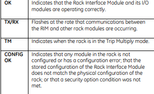
System configuration is secured by means of a keylock switch on the front of the TDI/RIM and two levels of software password protection, preventing unauthorized changes to or tampering with the configuration. Both the TDI and the RIM can be connected to a portable computer via a front-panel serial communications port for local changes to configuration. The RIM can also be permanently connected to a configuration workstation via a rear panel serial communications port, or to a remote computer via an optional modem I/O module. The TDI provides permanent system connectivity via Ethernet ports. The TDI/RIM provides a front-panel DIP switch that permits the user to assign a unique rack address when multiple 3500 racks are networked with one another. The TDI/RIM provides a system reset switch on the front panel, allowing the user to clear any latched alarms in the system as well as latched NOT OK conditions. An I/O module provides a set of rearpanel connections as well, allowing users to remotely activate this switch. For Triple Modular Redundant (TMR) applications, the 3500 System requires a TMR version of the
Monitors
Table 1 summarizes available monitor types in the 3500 System. Each monitor occupies a single slot in the rack. All monitors are microprocessor-based and offer digitally adjustable Alert and Danger setpoints for each channel1. Users can configure alarms for latching or non-latching operation. Status indications for each monitor and channel are provided with bright, front-panel LEDs, allowing observation without operator interaction for easy and convenient operation. Most monitors provide independent 4 to 20 mA proportional outputs for each channel of the I/O module for connection to strip chart recorders or for older process control systems that do not support a digital interface. Where applicable, the monitor’s I/O modules provide transducers with appropriate power via shortcircuit-protected terminals. OK detection routines within each monitor continuously check the integrity of each transducer and the associated field wiring. Transducer input signals are buffered and sent to front-panel coaxial connectors2. Buffered output terminals are also available upon request on the rear of the TDI/RIM’s I/O module.
Notes:
1. In addition to the direct measurement made by the monitor, many channel types provide an enhanced data set consisting of a variety of proportional values that will depend on the monitor type and its configuration. For example, for a radial vibration channel this includes the basic overall (direct) vibration amplitude as well as gap voltage, 1X filtered amplitude, 1X filtered phase, 2X filtered amplitude, 2X filtered phase, NOT 1X amplitude, and Smax. These additional proportional values are provided for each channel, and ALERT alarm setpoints can be established on each proportional value, as desired. DANGER alarm setpoints can be established on any two proportional values returned from each channel.
2. 3500/60, /62, and /63 monitor types do not provide front-panel buffered output connectors.
3. Only standard differential expansion capabilities provided. For ramp differential expansion and complementary input differential expansion, use the 3500/45 Position Monitor instead.
4. The 3500/42M provides individual 4 to 20 mA proportional outputs for each channel. The 3500/40M does not provide 4 to 20 mA outputs.
5. The monitor channels are programmed in pairs and can perform up to two of these functions at a time. Channels 1 and 2 can perform one function, while channels 3 and 4 perform another (or the same) function.
6. Channels configured for velocity or acceleration provide only direct amplitude. Channels configured for Velocity II or Acceleration II provide 1X amplitude/phase and 2X amplitude/phase in addition to direct amplitude.
7. Any vibration channel can be configured for conventional “pieshaped” acceptance region alarms. When configured for circular acceptance regions, circular, rather than pie-shaped, acceptance region alarms can be enabled. Refer to the 3500/42M Operations/Maintenance Manual for additional information, or contact your nearest sales professional.
8. Contact the factory or your local sales professional for details.
9. Only channels 3 and 4 can be used for Case Expansion measurements.
10. The 3500/46M provides frequency response characteristics suitable for use on machines with very slow rotational speeds, such as hydraulic turbine/generator sets, which often operate at speeds of 100 RPM or lower. Also, special signal conditioning and tracking filtering is provided, allowing detection of rough load zone operation, shear pin failure, and other hydro-specific conditions.
11. The 3500/50 is not intended for use in overspeed protection applications. Use the 3500/53 instead.
12. Zero speed functionality requires both channels of the 3500/50 module, making it a single-channel monitor.
13. The 3500/53 is a single channel module, intended for use as part of a 1-out-of-2 or 2-out-of-3 (recommended) overspeed detection system.
14. The 3500/60 and 3500/61 provide identical functions except the 3500/60 does not provide 4 to 20 mA proportional outputs. When these outputs are required, use the 3500/61.

.jpg)
.jpg)
.jpg)
.jpg)
.png)
.jpg)
.jpg)
_lVjBYb.jpg)
.jpg)
.jpg)
.jpg)
.jpg)
.jpg)
.jpg)
.jpg)
.jpg)
.jpg)
.jpg)
.jpg)
.jpg)
.jpg)
.jpg)
.jpg)
.jpg)
.jpg)
.jpg)

.jpg)
.jpg)
