Bently3500 System Overview
Features Digital and Analog Communications
Relays1

The 3500/32 Relay Module provides four double-pole, double throw (DPDT) relays that can actuate based on alarm conditions within 3500 monitor modules. The configuration software allows the user to program various combinations of alarms, ranging from an individual channel’s ALERT or DANGER status, to highly complex Boolean expressions that combine two or more channel statuses to provide special AND or OR voting. By adding the desired number of relay modules, the user can provide individual contacts for each channel, alarm type, and group of channels for global alarm annunciation.

The 3500/34 TMR Relay Module works in conjunction with a special TMR Rack Interface Module and three monitor modules to provide 2-out-of-3 voting for inputs. Relays are epoxy-sealed and installed arc suppressors are standard. Users can program relays for either normally energized or normally de-energized operation. The 3500 Rack also supplies a common system OK relay2 in addition to any alarm relays in the rack. This relay is located in the TDI/RIM’s I/O module and is connected to the OK circuits of all modules in the rack. These circuits monitor the operating condition of each module. Any fault in the module, its transducers, or associated transducer field wiring will be annunciated by the OK relay. This relay is a singlepole, double-throw (SPDT) type and is normally energized, providing added capability of annunciation in the event of primary power loss.
Notes:
1. Although not a required component of the 3500 System, we strongly recommend relays as the appropriate way to interconnect the 3500 System in auto-shutdown applications. Analog (e.g. 4 to 20 mA) and digital (e.g. Modbus*) connections are intended for operator annunciation and trending purposes and do not provide the fault tolerance or integrity necessary for highly reliable machinery shutdown purposes. 2. Dozens of possible event conditions within the rack can drive the NOT OK relay. For this reason, it is not intended for use as part of a
Keyphasor Inputs
The 3500 System can accommodate up to four1 Keyphasor transducers per rack by installing two 3500/25 Keyphasor modules in a rack2. Each 3500/25 is a half-height module that provides power and termination for up to two Keyphasor transducers each. When applications require Keyphasor transducers, simply install a single 3500/25 module. Keyphasor signals from the 3500/25 module(s) can be routed to appropriate monitor modules via the 3500’s rack backplane for use in speed, phase, tracking filter, and other measurements.
Notes: 1. When more than four Keyphasor transducers must be used in a single rack, contact the factory for details regarding special modifications available. 2. When two 3500/25 modules are used, they must be installed in the same rack slot, one above the other.
Communications Gateway

With an appropriate Communications Gateway module in the rack, installations can digitally transfer selected status and current value data to process control systems, historians, plant computers, and other relevant systems. The Communication Gateway modules support a variety of industry-standard protocols and users can install multiple Communications Gateway modules in a rack when the system requires redundant communications or must support multiple communication protocols simultaneously. The modules do not interfere with the 3500 System’s normal operations or machinery protection functions, ensuring that the monitoring system integrity is always maintained, even in the unlikely event of a Communications Gateway module failure. The Communications Gateway supports both Ethernet and serial communications media, allowing a variety of wired and wireless topologies. Communications are bi-directional, allowing selected data to be sent to and retrieved from the 3500 System. In addition, when installations use Ethernet to connect the Communications Gateway to process control or other systems, multiple computers running 3500 Configuration Software and/or 3500 Operator Display Software can reside on the same network. This
Notes
tes: 1. For this mounting option only, the Display Interface Module (DIM) must occupy slot 15 (right-most slot) of the rack.
2. With the use of a special external power supply, the display can be located up to 1219 metres (4000 feet) from the 3500 System.
3. It is recommended that the display be located within 7.6 metres (25 feet) of the 3500 rack., as the video driver circuit is optimized for this range. Lengths above 25 feet will degrade the picture quality. When an extension is necessary, a special KVM Extender is available. However, even with the KVM Extender, there will be some reduction in picture quality. Typically, the picture image will still be acceptable. The KVM Extender must be used indoors, and it is not rated for use in hazardous areas.
4. Distances greater than 4000 feet are supported when Ethernet, rather than serial communications, is used between the rack and the 3500/95 display. Wireless Ethernet can also be used.
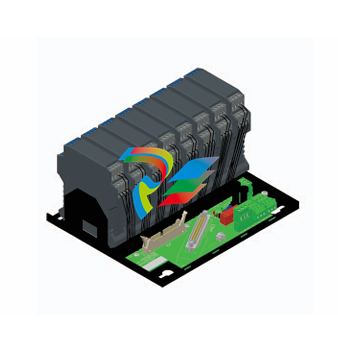
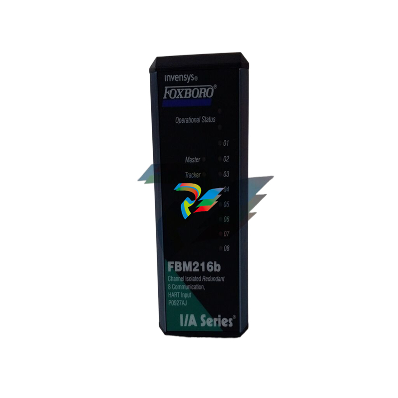
Intrinsic Safety Barriers or Galvanic Isolators

.jpg)
.jpg)
.jpg)

.jpg)
.png)
.jpg)
.jpg)
_lVjBYb.jpg)
.jpg)
.jpg)
.jpg)
.jpg)
.jpg)
.jpg)
.jpg)
.jpg)
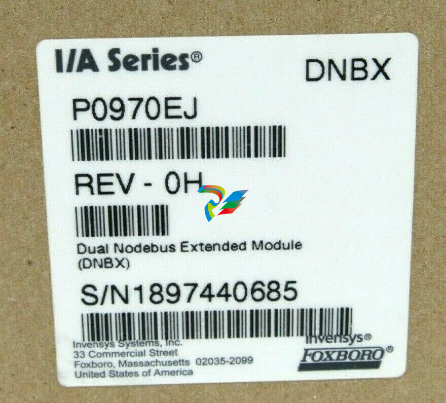
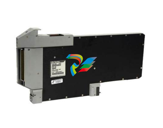
.jpg)
.jpg)
.jpg)
.jpg)
.jpg)
.jpg)
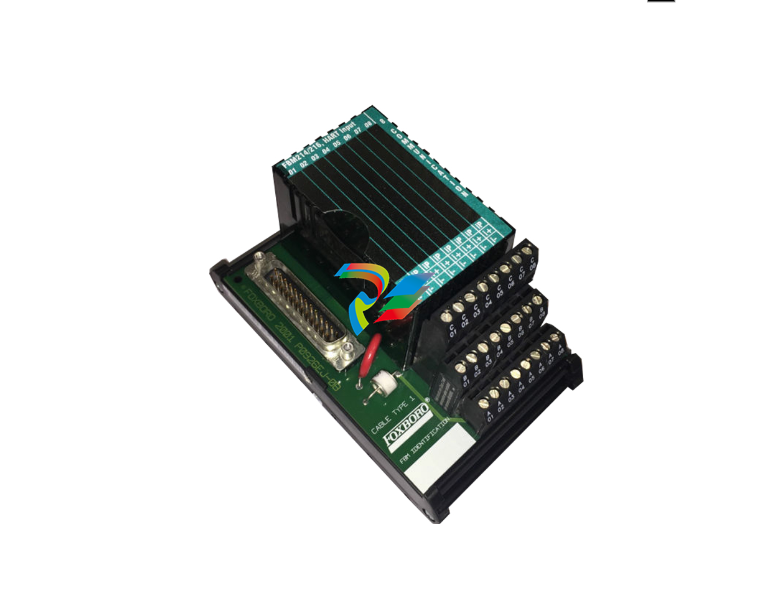
.jpg)
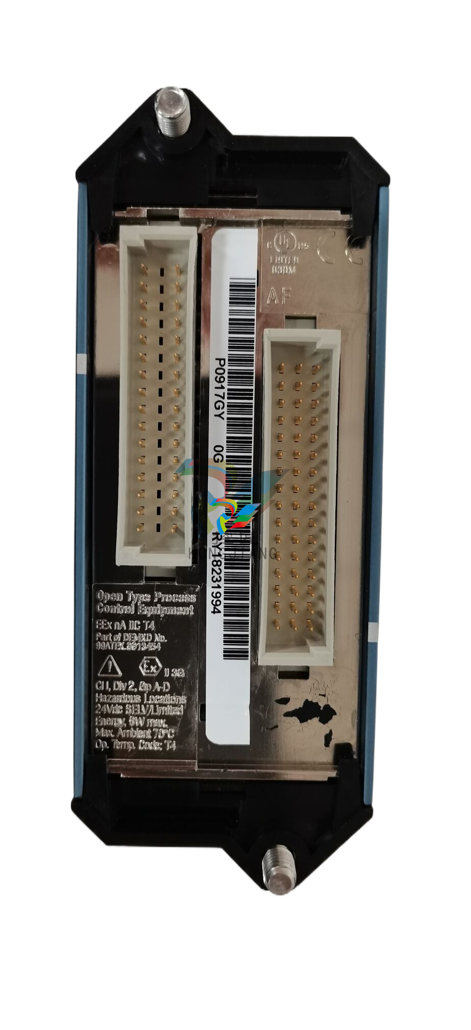
.jpg)
.jpg)
.jpg)

.jpg)
.jpg)

