
Bently3500 System Overview
Description
The 3500 System provides continuous, online monitoring suitable for machinery
protection applications, and is designed to fully meet the requirements of the
American Petroleum Institute’s API 670 standard for such systems. It represents
our most capable and flexible system in a traditional rack-based design, and
represents numerous features and advantages not provided in other systems.
The system’s highly modular design consists of:
• 3500/05 Instrument Rack (required)
• One or two 3500/15 Power Supplies (required)
• 3500/22M Transient Data Interface or 3500/20 Rack Interface Module (required) • One or two 3500/25 Keyphasor® Modules (optional) • 3500 Rack Configuration Software (required)
• One or more 3500/XX Monitor Modules (required)
• One or more 3500/32 Relay Modules or 3500/34 TMR Relay Modules (optional) • One or more 3500/92 Communication Gateway Modules (optional)
• 3500/93, 3500/94, or 3500/95 display OR 3500 Operator Display Software running on a compatible PC (optional)
• Internal or external intrinsic safety barriers, or galvanic isolators for hazardous area installations (optional) These are described in more detail in the following section and in the individual datasheets for each system component.
System Components
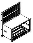
Rack The full-size 3500 Rack is available in 19” EIA railmount, panel-cutout-mount, and bulkhead-mount versions. The rack provides slots for two Power Supplies and a Rack Interface Module in the left-most rack positions that are reserved exclusively for these modules. The remaining 14 slots in the rack can accommodate any combination of monitor, display, relay, Keyphasor module, and communications gateway modules. All modules plug into the rack’s backplane and consist of a main module and an associated I/O module. The I/O module installs at the rear of the rack for panel-mount systems, and above the main module for bulkhead-mount systems. The rack depth is 349 mm (13.75 inches) and NEMA 4 and 4X weatherproof housings are available when required for environmental protection or when purge air is used. A mini-rack (12” wide instead of 19”) is also available and features 7 available monitor slots instead of 14. Like its larger counterpart, the left-most slots are reserved for the Power Supply or Supplies and Rack Interface Module. The mini-rack may be mounted in a panel cutout or, using an optional adapter plate, on 19” EIA mounting rails. Bulkhead mounting is not available.
Power Supply
The 3500/15 Power Supply can be ordered for ac or dc input power, providing compatibility with voltage sources worldwide. Line noise filters are standard. The 3500 Rack can operate from a single supply, or dual Power Supplies can provide redundancy for situations which cannot tolerate power interruption. Dual supplies reside in the upper and lower positions of the left-most rack slot. Redundant Power Supplies can use with separate voltage sources. For example, the primary (bottom) supply can be operate with 120 Vac power while the backup (upper) supply can be powered from an uninterruptible 24 Vdc source. Each Power Supply can individually provide power to the entire rack and its modules. When redundant supplies are used, one supply acts as primary power for the rack while the other acts as a backup, ready to instantly and automatically operate as the primary rack supply without interrupting rack functions., should the primary supply fail. The 3500/15 Power Supply module has selfmonitoring functions that allow it to determine if all its output voltages are within specifications. The module annunciates this via a green “Supply OK” LED on the Power Supply’s front panel.
Rack Interface Module/Transient Data Interface
The Transient Data Interface (TDI) or the Rack Interface Module (RIM) are the 3500 Rack’s primary interfaces to the configuration, display, and condition monitoring software. Each rack requireas one TDI or RIM, which resides in the rack slot immediately adjacent to the Power Supply slot. The TDI and RIM support a proprietary protocol used by both the 3500 Configuration Software to configure the rack and the 3500 Operator Display Software to retrieve rack data and statuses. TDI provides a direct interface with GE’s Bently Nevada System 1® machinery management software without the need for an external communications processor. The RIM requires an external communications processor, such as TDXnet™, TDIX, or DDIX to interface to Data Manager® condition monitoring software. The System OK relay1 is located within the TDI/RIM’s I/O module. It is driven by NOT OK conditions within the TDI/RIM itself and within other modules in the rack.
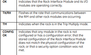
The TDI and RIM supply “self monitoring” functions both for themselves and for the rack, in addition to those provided by the individual monitor, relay, communications, and other modules. While the TDI and RIM provide certain functions common to the entire rack, neither is part of the critical monitoring path and has no effect on the proper, normal operation of the overall 3500 System or its machinery protection functions. The TDI and RIM provide 4 front-panel LEDs as follows:
System configuration is secured by means of a keylock switch on the front of the TDI/RIM and two levels of software password protection, preventing unauthorized changes to or tampering with the configuration. Both the TDI and the RIM can be connected to a portable computer via a front-panel serial communications port for local changes to configuration. The RIM can also be permanently connected to a configuration workstation via a rear panel serial communications port, or to a remote computer via an optional modem I/O module. The TDI provides permanent system connectivity via Ethernet ports. The TDI/RIM provides a front-panel DIP switch that permits the user to assign a unique rack address when multiple 3500 racks are networked with one another. The TDI/RIM provides a system reset switch on the front panel, allowing the user to clear any latched alarms in the system as well as latched NOT OK conditions. An I/O module provides a set of rearpanel connections as well, allowing users to remotely activate this switch. For Triple Modular Redundant (TMR) applications, the 3500 System requires a TMR version of the
Monitors
Table 1 summarizes available monitor types in the 3500 System. Each monitor occupies a single slot in the rack. All monitors are microprocessor-based and offer digitally adjustable Alert and Danger setpoints for each channel1. Users can configure alarms for latching or non-latching operation. Status indications for each monitor and channel are provided with bright, front-panel LEDs, allowing observation without operator interaction for easy and convenient operation. Most monitors provide independent 4 to 20 mA proportional outputs for each channel of the I/O module for connection to strip chart recorders or for older process control systems that do not support a digital interface. Where applicable, the monitor’s I/O modules provide transducers with appropriate power via shortcircuit-protected terminals. OK detection routines within each monitor continuously check the integrity of each transducer and the associated field wiring. Transducer input signals are buffered and sent to front-panel coaxial connectors2. Buffered output terminals are also available upon request on the rear of the TDI/RIM’s I/O module.
Notes:
1. In addition to the direct measurement made by the monitor, many channel types provide an enhanced data set consisting of a variety of proportional values that will depend on the monitor type and its configuration. For example, for a radial vibration channel this includes the basic overall (direct) vibration amplitude as well as gap voltage, 1X filtered amplitude, 1X filtered phase, 2X filtered amplitude, 2X filtered phase, NOT 1X amplitude, and Smax. These additional proportional values are provided for each channel, and ALERT alarm setpoints can be established on each proportional value, as desired. DANGER alarm setpoints can be established on any two proportional values returned from each channel.
2. 3500/60, /62, and /63 monitor types do not provide front-panel buffered output connectors.
3. Only standard differential expansion capabilities provided. For ramp differential expansion and complementary input differential expansion, use the 3500/45 Position Monitor instead.
4. The 3500/42M provides individual 4 to 20 mA proportional outputs for each channel. The 3500/40M does not provide 4 to 20 mA outputs.
5. The monitor channels are programmed in pairs and can perform up to two of these functions at a time. Channels 1 and 2 can perform one function, while channels 3 and 4 perform another (or the same) function.
6. Channels configured for velocity or acceleration provide only direct amplitude. Channels configured for Velocity II or Acceleration II provide 1X amplitude/phase and 2X amplitude/phase in addition to direct amplitude.
7. Any vibration channel can be configured for conventional “pieshaped” acceptance region alarms. When configured for circular acceptance regions, circular, rather than pie-shaped, acceptance region alarms can be enabled. Refer to the 3500/42M Operations/Maintenance Manual for additional information, or contact your nearest sales professional.
8. Contact the factory or your local sales professional for details.
9. Only channels 3 and 4 can be used for Case Expansion measurements.
10. The 3500/46M provides frequency response characteristics suitable for use on machines with very slow rotational speeds, such as hydraulic turbine/generator sets, which often operate at speeds of 100 RPM or lower. Also, special signal conditioning and tracking filtering is provided, allowing detection of rough load zone operation, shear pin failure, and other hydro-specific conditions.
11. The 3500/50 is not intended for use in overspeed protection applications. Use the 3500/53 instead.
12. Zero speed functionality requires both channels of the 3500/50 module, making it a single-channel monitor.
13. The 3500/53 is a single channel module, intended for use as part of a 1-out-of-2 or 2-out-of-3 (recommended) overspeed detection system.
14. The 3500/60 and 3500/61 provide identical functions except the 3500/60 does not provide 4 to 20 mA proportional outputs. When these outputs are required, use the 3500/61.
15. The 3500/62 is designed to accept static proportional signals such as 4 to 20 mA, 1 to 5 Vdc, or any static proportional signal between –10 and +10 Vdc. When dynamic signals (i.e., those where waveform information is required) are used, a 3500/40M or 3500/42M can often be programmed as a custom channel type to such signals, making the 3500 system compatible with virtually any static or dynamic signal from pressure, level, temperature, vibration, flow, position, speed, or other transducers. Consult the factory or your local Bently Nevada sales professional for more information.
16. The 3500/64M is primarily intended for monitoring combustor pressure pulsation instabilities (“humming”) in gas turbines.
Relays1

The 3500/34 TMR Relay Module works in conjunction with a special TMR Rack Interface Module and three monitor modules to provide 2-out-of-3 voting for inputs. Relays are epoxy-sealed and installed arc suppressors are standard. Users can program relays for either normally energized or normally de-energized operation. The 3500 Rack also supplies a common system OK relay2 in addition to any alarm relays in the rack. This relay is located in the TDI/RIM’s I/O module and is connected to the OK circuits of all modules in the rack. These circuits monitor the operating condition of each module. Any fault in the module, its transducers, or associated transducer field wiring will be annunciated by the OK relay. This relay is a singlepole, double-throw (SPDT) type and is normally energized, providing added capability of annunciation in the event of primary power loss.
Notes:
1. Although not a required component of the 3500 System, we strongly recommend relays as the appropriate way to interconnect the 3500 System in auto-shutdown applications. Analog (e.g. 4 to 20 mA) and digital (e.g. Modbus*) connections are intended for operator annunciation and trending purposes and do not provide the fault tolerance or integrity necessary for highly reliable machinery shutdown purposes. 2. Dozens of possible event conditions within the rack can drive the NOT OK relay. For this reason, it is not intended for use as part of a
Notes:1. For this mounting option only, the Display Interface
Module (DIM) must occupy slot 15 (right-most slot) of
the rack.
2. With the use of a special external power supply, the
display can be located up to 1219 metres (4000 feet)
from the 3500 System.
3. It is recommended that the display be located within
7.6 metres (25 feet) of the 3500 rack., as the video
driver circuit is optimized for this range. Lengths above
25 feet will degrade the picture quality. When an
extension is necessary, a special KVM Extender is
available. However, even with the KVM Extender, there
will be some reduction in picture quality. Typically, the
picture image will still be acceptable. The KVM Extender
must be used indoors, and it is not rated for use in
hazardous areas.
4. Distances greater than 4000 feet are supported when
Ethernet, rather than serial communications, is used
between the rack and the 3500/95 display. Wireless
Ethernet can also be used.
Intrinsic Safety Barriers or Galvanic Isolators
For applications where the transducers are located in a hazardous area, the 3500 System can be used with internal or external intrinsic safety barriers. However, the 3500 option for internal safety barriers is generally preferable to external barriers because this option saves cost, requires no extra cabinet space, and needs no additional wiring. Internal barriers improve safety because the connections are pre-wired, reducing the possibility for errors introduced by wiring additional external connections between monitors and barriers. Internal barriers also improve quality because, unlike external barriers, they require no special monitor scale factor calibration to compensate for voltage drop across the barrier. For additional information on 3500 internal barriers, refer to datasheet 141495-01. For those that prefer the use of galvanic isolators to address intrinsic safety requirements, preengineered external galvanic isolators and an appropriate housing are available. For additional information on 3500 galvanic isolators, refer to datasheet 141714-01.
Applications
The 3500 System is intended for continuous, permanent monitoring of rotating and reciprocating machinery in a variety of industries. It is specifically designed for use in auto-shutdown machinery protection applications that require extremely high reliability and availability. Machine types addressed by the 3500 System include but are not limited to: Industrial gas and steam turbines in power generation and mechanical drive service Aeroderivative gas turbines in power generation and mechanical drive service Hydraulic (Hydro) turbines in power generation service Compressors (air/process gas, radial/axial, centrifugal/positive displacement) Turbo Expanders Electric motors and generators Exciters Gear boxes Pumps (centrifugal and positive displacement) Fans Blowers Reciprocating compressors Extruders and pelletizers In addition, GE’s Bently Nevada Custom Products engineering, can often address special requirements for custom configuration of an existing monitor type or modifications to a standard monitor type. Contact your local sales professional for further information.
Features Digital and Analog Communications
Relays1
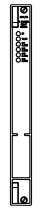
The 3500/32 Relay Module provides four double-pole, double throw (DPDT) relays that can actuate based on alarm conditions within 3500 monitor modules. The configuration software allows the user to program various combinations of alarms, ranging from an individual channel’s ALERT or DANGER status, to highly complex Boolean expressions that combine two or more channel statuses to provide special AND or OR voting. By adding the desired number of relay modules, the user can provide individual contacts for each channel, alarm type, and group of channels for global alarm annunciation.

The 3500/34 TMR Relay Module works in conjunction with a special TMR Rack Interface Module and three monitor modules to provide 2-out-of-3 voting for inputs. Relays are epoxy-sealed and installed arc suppressors are standard. Users can program relays for either normally energized or normally de-energized operation. The 3500 Rack also supplies a common system OK relay2 in addition to any alarm relays in the rack. This relay is located in the TDI/RIM’s I/O module and is connected to the OK circuits of all modules in the rack. These circuits monitor the operating condition of each module. Any fault in the module, its transducers, or associated transducer field wiring will be annunciated by the OK relay. This relay is a singlepole, double-throw (SPDT) type and is normally energized, providing added capability of annunciation in the event of primary power loss.
Notes:
1. Although not a required component of the 3500 System, we strongly recommend relays as the appropriate way to interconnect the 3500 System in auto-shutdown applications. Analog (e.g. 4 to 20 mA) and digital (e.g. Modbus*) connections are intended for operator annunciation and trending purposes and do not provide the fault tolerance or integrity necessary for highly reliable machinery shutdown purposes. 2. Dozens of possible event conditions within the rack can drive the NOT OK relay. For this reason, it is not intended for use as part of a
Keyphasor Inputs
The 3500 System can accommodate up to four1 Keyphasor transducers per rack by installing two 3500/25 Keyphasor modules in a rack2. Each 3500/25 is a half-height module that provides power and termination for up to two Keyphasor transducers each. When applications require Keyphasor transducers, simply install a single 3500/25 module. Keyphasor signals from the 3500/25 module(s) can be routed to appropriate monitor modules via the 3500’s rack backplane for use in speed, phase, tracking filter, and other measurements.
Notes: 1. When more than four Keyphasor transducers must be used in a single rack, contact the factory for details regarding special modifications available. 2. When two 3500/25 modules are used, they must be installed in the same rack slot, one above the other.
Communications Gateway
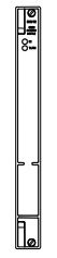
With an appropriate Communications
Gateway module in the rack, installations
can digitally transfer selected status and
current value data to process control
systems, historians, plant computers, and
other relevant systems. The
Communication Gateway modules
support a variety of industry-standard
protocols and users can install multiple
Communications Gateway modules in a
rack when the system requires redundant
communications or must support multiple
communication protocols simultaneously.
The modules do not interfere with the
3500 System’s normal operations or
machinery protection functions, ensuring
that the monitoring system integrity is always
maintained, even in the unlikely event of a
Communications Gateway module failure.
The Communications Gateway supports both Ethernet
and serial communications media, allowing a variety
of wired and wireless topologies. Communications are
bi-directional, allowing selected data to be sent to and
retrieved from the 3500 System. In addition, when
installations use Ethernet to connect the
Communications Gateway to process control or other
systems, multiple computers running 3500
Configuration Software and/or 3500 Operator Display
Software can reside on the same network. This
Notes
tes: 1. For this mounting option only, the Display Interface Module (DIM) must occupy slot 15 (right-most slot) of the rack.
2. With the use of a special external power supply, the display can be located up to 1219 metres (4000 feet) from the 3500 System.
3. It is recommended that the display be located within 7.6 metres (25 feet) of the 3500 rack., as the video driver circuit is optimized for this range. Lengths above 25 feet will degrade the picture quality. When an extension is necessary, a special KVM Extender is available. However, even with the KVM Extender, there will be some reduction in picture quality. Typically, the picture image will still be acceptable. The KVM Extender must be used indoors, and it is not rated for use in hazardous areas.
4. Distances greater than 4000 feet are supported when Ethernet, rather than serial communications, is used between the rack and the 3500/95 display. Wireless Ethernet can also be used.
Intrinsic Safety Barriers or Galvanic Isolators
For applications where the transducers are located in a hazardous area, the 3500 System can be used with internal or external intrinsic safety barriers. However, the 3500 option for internal safety barriers is generally preferable to external barriers because this option saves cost, requires no extra cabinet space, and needs no additional wiring. Internal barriers improve safety because the connections are pre-wired, reducing the possibility for errors introduced by wiring additional external connections between monitors and barriers. Internal barriers also improve quality because, unlike external barriers, they require no special monitor scale factor calibration to compensate for voltage drop across the barrier. For additional information on 3500 internal barriers, refer to datasheet 141495-01. For those that prefer the use of galvanic isolators to address intrinsic safety requirements, preengineered external galvanic isolators and an appropriate housing are available. For additional information on 3500 galvanic isolators, refer to datasheet 141714-01.
Applications
The 3500 System is intended for continuous, permanent monitoring of rotating and reciprocating machinery in a variety of industries. It is specifically designed for use in auto-shutdown machinery protection applications that require extremely high reliability and availability. Machine types addressed by the 3500 System include but are not limited to
Industrial gas and steam turbines in power generation and mechanical drive service Aeroderivative gas turbines in power generation and mechanical drive service Hydraulic (Hydro) turbines in power generation service Compressors (air/process gas, radial/axial, centrifugal/positive displacement) Turbo Expanders Electric motors and generators Exciters Gear boxes Pumps (centrifugal and positive displacement) Fans Blowers Reciprocating compressors Extruders and pelletizers In addition, GE’s Bently Nevada Custom Products engineering, can often address special requirements for custom configuration of an existing monitor type or modifications to a standard monitor type. Contact your local sales professional for further information.
Features Digital and Analog Communications The 3500 System features separate, concurrent digital communication capabilities for connection to:
System 1 machinery management software using Bently Nevada proprietary protocols via Ethernet connections Process control and other plant automation systems using industry-standard protocols via the 3500’s Communications Gateway module Bently Nevada condition monitoring systems via pre-engineered Data Manager ports which interface to an appropriate external communications processor such as TDXnet, TDIX, or DDIX 3500 Configuration and Display software In addition, analog (4 to 20 mA and relay) outputs are available for connection to older plant controls that cannot support digital interfaces.
-
 AEROTECH SM Series High-Performance Stepper Motors
 -
 AEROTECH BLMSC Series Linear Motors
 -
 AEROTECH Custom Linear Motors
 -
 AEROTECH BMS Series Brushless, Slotless Rotary Motors
 -
 AEROTECH BM Series Brushless Rotary Motors
 -
 AEROTECH BLMX Series Linear Motors
 -
 AEROTECH BLMH Series Linear Motors
 -
 AEROTECH BLM Series Linear Motors
 -
 AEROTECH BLMC Series Linear Motors
 -
 AEROTECH BLMUC-143 Linear motor forcer with thermistor
 -
AEROTECH BLMUC-111 Linear motor forcer with thermistor
-
AEROTECH BLMUC-95 Linear motor forcer with thermistor
-
AEROTECH BLMUC-79 Linear motor forcer with thermistor
-
AEROTECH BLMUC Series Linear Motors
-
 AEROTECH Automation1 FLEX Distributed Amplifier Multi-Axis Servo Control System
 -
 AEROTECH Automation1 HXA4 6-Axis Hexapod Servo Drive
 -
 AEROTECH Automation1 iHXA4 6-Axis Hexapod Servo Drive with Motion Controller
 -
 AEROTECH Modular System Control Console
 -
 AEROTECH TV Series Transformers
 -
 AEROTECH TM Series Transformers
 -
 AEROTECH UFM Noise Filter Module
 -
 AEROTECH MFM Motor Filter Module
 -
 AEROTECH MPG Handwheel Pendant
 -
 AEROTECH Automation1 Multi-Axis Joystick
 -
 AEROTECH ETM Enhanced Throughput Module
 -
 AEROTECH Automation1 XL4s High-Speed, Single-Phase Linear Servo Drive
 -
 AEROTECH Automation1 XL2e Enhanced, Compact Linear Servo Drive
 -
 Automation1 iXL2e Enhanced, Compact Linear Servo Drive with Motion Controller
 -
 AEROTECH Automation1 XL5e Enhanced, Linear Servo Drive
 -
 AEROTECH Automation1 iXL5e Enhanced Linear Servo Drive with Motion Controller
 -
 AEROTECH Automation1 GI4 Laser Scan Head Controller
 -
 AEROTECH Automation1 SI4 Stepper Interface
 -
AEROTECH Automation1 XI4 Servo Interface
-
 AEROTECH AEROTECH Automation1 iXI4 Servo Interface with Motion Controller
 -
 AEROTECH Automation1 XC6e Enhanced, High-Power PWM Servo Drive
 -
 AEROTECH Automation1 iXC6e Enhanced, High-Power PWM Servo Drive with Motion Controller
 -
 AEROTECH Automation1 XC2 Compact PWM Servo Drive
 -
 AEROTECH Automation1 XC4 PWM Servo Drive
 -
 AEROTECH Automation1 GL4 Galvo Laser Scan Head Linear Drive
 -
 AEROTECH Automation1 XC2e Enhanced, Compact Servo Drive with PWM+
 -
 AEROTECH Automation1 XC4e Enhanced, PWM Servo Drive
 -
 AEROTECH Automation1 XR3 Multi-Axis Servo Drive Rack
 -
 AEROTECH Automation1 iXR3 Multi-Axis Servo Drive Rack with Motion Controller
 -
 AEROTECH Automation1 iXC2 Compact PWM Servo Drive with Motion Controller
 -
 AEROTECH Automation1 iXC2e Enhanced, Compact PWM+ Servo Drive with Motion Controller
 -
 AEROTECH Automation1 iXC4 PWM Servo Drive with Motion Controller
 -
 AEROTECH Automation1 iXC4e Enhanced, PWM Servo Drive with Motion Controller
 -
 AEROTECH Automation1 iPC Industrial PC with Motion Controller
 -
 AEROTECH EPICS & TANGO Drivers for Distributed Control Systems
 -
 AEROTECH .NET, C, Python & LabVIEW APIs Custom Application Develotpmen
 -
 AEROTECH Automation1 Industrial Ethernet Support
 -
 AEROTECH Automation1 iSMC Intelligent, Software-Based Motion Controller
 -
 AEROTECH Automation1 iXA4 1- 2- or 4-Axis PWM Servo Drive with Motion Controller
 -
 AEROTECH Automation1 XA4 1- 2- or 4-Axis PWM Servo Drive
 -
 CTI 2500-ADP2-DISC Discrete Wiring Adapter for Series 500
 -
 CTI 2500-ADP1 Analog Wiring Adapter for Series 500
 -
 CTI 2500C-RADP-RS485 Remote Base Controller Adapter for Series 500
 -
 CTI 2500C-RADP-RBC Profibus RBC Adapter for Series 500
 -
 CTI 2500C-PADP-120V 120VAC 50W Power Supply for Series 500
 -
 CTI 2500-RADP RBC Adapter for Series 500
 -
 CTI 2500-R4500 520/530/DBC Adapter for Series 500 - MATURE
 -
 CTI 2500-PADP Power Supply Adapter for Series 500
 -
 CTI 2500-IADP I/O Adapter for Series 500
 -
 CTI 2500-VP15A-N4-W7 15" Flat-Panel PC with Windows® 7 Embedded
 -
 CTI 2500S-27-1750 Slice I/O, Ethernet, RS232/485. 900MHz, 2DIO / 4UAI / 2AI
 -
 CTI 2500S-26-1750 Slice I/O, Ethernet, RS232/485. 900MHz, 8DIO / 2UAI
 -
 CTI 2500S-23-1750 Slice I/O, Ethernet, RS232/485. 900MHz, 4DI / 4DO / 2UAI / 2AO
 -
 CTI 2500S-27-1550 Slice I/O, RS232/485. 2DIO / 4UAI / 2AI
 -
 CTI 2500S-26-1550 Slice I/O, RS232/485. 8DIO / 2UAI
 -
 CTI 2500S-23-1550 Slice I/O, RS232/485. 4DI / 4DO / 2UAI / 2AO
 -
 CTI 2500S-27-1050 Slice I/O, Ethernet, 2DIO / 4UAI / 2AI
 -
 CTI 2500S-26-1050 Slice I/O, Ethernet, 8DIO / 2UAI
 -
 CTI 2500S-23-1050 Slice I/O, Ethernet, 4DI / 4DO / 2UAI / 2AO
 -
 CTI 2500C-32F-CJC 32-Pin Field Wiring Connector with Cold Junction Compensation
 -
 CTI 2500C-32F 32-Pin Field Wiring Connector
 -
 CTI 2500C-8-TC Eight Thermocouple Inputs
 -
 CTI 2500C-8-RTD Eight RTD Inputs
 -
 CTI 2500C-8-RL-FC 8 Form-C Relay Outputs
 -
 CTI 2500C-8-IDO-24V 8 Isolated 24VDC Outputs
 -
 CTI 2500C-8-IDO-120V 8 Isolated 120VAC Outputs
 -
 CTI 2500C-16-DO-24V Sixteen 24VDC Digital Outputs
 -
 CTI 2500C-16-DO-120V Sixteen 120VAC Digital Outputs
 -
.png) CTI 500C-16-IDI-24V Sixteen Isolated 24V AC/DC Digital Inputs
CTI 500C-16-IDI-24V Sixteen Isolated 24V AC/DC Digital Inputs -
 CTI 2500C-16-IDI-120V Sixteen Isolated 120V AC/DC Digital Inputs
 -
 CTI 2500C-16-DIDO-SIM Sixteen Digital Input and Output SImulator
 -
 CTI 2500C-16-DI-24V Sixteen 24V AC/DC Digital Inputs
 -
 CTI 2500C-16-DI-120V Sixteen 120V AC/DC Digital Inputs
 -
 CTI 2500C-RBC-RS485 RS485 Remote Base Controller
 -
 CTI 2500C-RBC-PRF Profibus Remote Base Controller
 -
 CTI 2500C-PS-24V-35 35-Watt DC Power Supply
 -
 CTI 2500C-PS-120V-35 35-Watt AC Power Supply
 -
 CTI 2500C-R8 Eight-Slot Base
 -
 CTI 2500C-R4 Four-Slot Base
 -
 CTI 2500C-R16 Sixteen-Slot Base
 -
 CTI 2500C-2572-B Fast Ethernet TCP/IP Adapter
 -
 CTI 2500C-J750 Compact Janus PAC with 3MB Project Memory
 -
 CTI 2500C-C300 CPU with 512K User Memory
 -
 CTI 2500C-C200 CPU with 256K User Memory
 -
 CTI 2500C-C100 CPU with 128K User Memory
 -
 CTI 2500C-8-AO 8 Analog Outputs
 -
 CTI 2500C-8-AI 8 Analog Inputs
 -
 CTI 2559-FCAL Precision Calibration Connector
 -
 CTI 2559-FPC 40-Position Screw-Terminal Connector
 -
 CTI 2500-RFC PLC to RF Modem Cable
 -
 CTI 2500-40F 40-Position Standard Screw-Terminal Connector
 -
 CTI 2505 Vibration Sensor Interface Module
 -
 CTI 2554-A 4-Channel Isolated High Speed Counter Module
 -
 CTI 2553-A 2-Channel Mag Meter Input Module
 -
 CTI 2502 2-Channel High Speed Counter Input Module
 -
 CTI 2559-TC 8-Channel Thermocouple Input Module
 -
 CTI 2556-A 16-Channel Isolated Thermocouple Input Module
 -
 CTI 2556 16-Channel Isolated Thermocouple Input Module
 -
 CTI 2551-A 8-Channel Isolated Thermocouple Input Module
 -
 CTI 2559-RTD 8-Channel RTD Input Module
 -
 CTI 2557-A 16-Channel RTD Input Module
 -
 CTI 2557 16-Channel RTD Input Module
 -
 CTI 2552-A 8-Channel Isolated RTD Input Module
 -
 CTI 2534 8-Point Form-C Relay Output Module
 -
 CTI 2532 16-Point Form-A Relay Output Module
 -
 CTI 2531 32-Point Form-A Relay Output Module
 -
 CTI 2530 8-Point Form-C Relay Output Module
 -
 CTI 2562 8-Channel Analog Output Module
 -
 CTI 2560-A 8-Channel Isolated Analog Output Module
 -
 CTI 2501 8in/4out Analog Module
 -
 CTI 2558 8-Channel Analog Input Module
 -
 CTI 2555-A 16-Channel Analog Input Module
 -
 CTI 2550-A 8-Channel Isolated Analog Input Module
 -
 CTI 2599 8/16/32-Point AC Output Module


