A-BLC Series Linear MotorsUSER MANUAL
2. Verify that the flatness of the surface to which the magnet plate is to be
mounted is 0.005 in. Total Indicator Reading (TIR) per 12.0 inches. This
specification correlates to the overall flatness requirement of 0.005 in.
(.127 mm).
3. Prior to any component installation, verify that the opening for the
magnet plate and coil is dimensioned per Table 2.M.
Never try to place the motor coil assembly directly on the
magnet plates. Serious damage may result. Due to magnetic
attraction.
those responsible for the application and use of this motor assembly must
satisfy themselves that all necessary steps have been taken to assure that each
application and use meets all performance and safety requirements, including
any applicable laws, regulations, codes and standards.
The illustrations, charts, sample programs and layout examples shown in this
guide are intended solely for purposes of example. Since there are many
variables and requirements associated with any particular installation, Anorad
does not assume responsibility or liability (to include intellectual property
liability) for actual use based upon the examples shown in this publication.
Reproduction of the contents of this copyrighted publication, in whole or part,
without written permission of Anorad Corporation, is prohibited.
Throughout this manual we use notes to make you aware of safety
considerations:

Attention statements help you to:
• identify a hazard
• avoid a hazard
• recognize the consequences
IMPORTANT Identifies information that is critical for successful
application and understanding of the product.
Introduction
Using This Manual This motor manual is designed to help you install, integrate and start-up your
new Anorad Linear Motor. You do not have to be an expert in motion control.
However, this manual does assume you have a fundamental understanding of
basic electronics, mechanics, as well as motion control concepts and applicable
safety procedures.
The intent of this manual is to assist the user in the mechanical and electrical
installation of the Anorad LC Series Linear Motor.
Read this entire manual before you attempt to install your linear motor into
your motion system. Doing so will familiarize you with the linear motor
components and their relationship to each other and the system
After installation, check all system parameters to insure you have configured
your linear motor into your motion system properly.
Be sure to follow all instructions carefully and lastly but foremost pay special
attention to safety concerns.
Product Description General
The LC Linear Motor Series is described in this section. Product features are
explored and the part numbering system is explained. This basic information
will help you develop an understanding of the linear motor’s basic
configuration. This configuration information is then used as the fundamental
understanding required to guide you through the rest of this manual.
Product Line Description
Anorad's LC Series of steel core linear motors represents the most advanced
linear motor technology available. The LC linear motor utilizes a unique patent
pending laminated steel core design. Coupled with the latest magnetic
materials and optimized by Finite Element Analysis (FEA), a very high force
density is achieved. The LC Linear Motors ares available in models with
continuous forces from 84.5 N to 5658 N, (19 lbf to 1272 lbf), and peak forces
from 195.7N to 9314 N, (44 lbf to 2094 lbf). Other frame sizes are available
with higher forces.
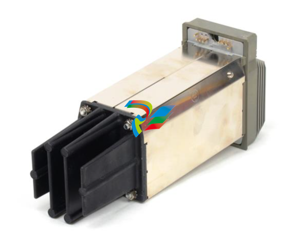
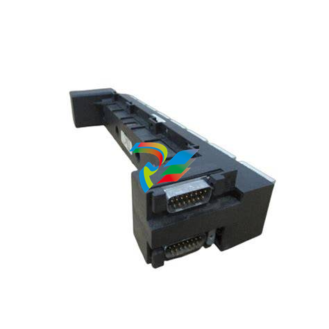
For servo drives that require commutation feedback, an optional trapezoidal
(digital) Hall effect feedback module may be attached to the front of the motor
coil. The LC may also be commutated via software. Anorad offers a full line of
compatible servo controls and drives.
Motor Features
• Steel core design for high force density
• Sinusoidal flux density and low-cog design yields smooth motion
• Robust design for heavy duty applications
• Modular magnet tracks permit unlimited travel
• Internal thermal sensor gives added motor protection
Maintenance Anorad linear motors require no maintenance when operated in a relative clean
environment. For operation in harsh and dirty environments minimal clean is
recommended every 6 months:
• Clean the metallic debris and other contaminants from the air gap. To
effectively remove the metal debris use a strip of masking tape.
Simply put a strip of tape on the magnet track an then remove it.
Keeping the magnet track clean will prevent witness marks. Witness
marks are caused by metal debris being dragged across the surface of
the stainless steel by the magnet field of the moving coil. Witness
marks have no effect on the performance of the motor.
Installation
Unpacking and Inspection Inspect motor assemblies to make certain no damage has occurred in
shipment. Any damage or suspected damage should be immediately



.jpg)
.jpg)
.jpg)

.jpg)
.png)
.jpg)
.jpg)
_lVjBYb.jpg)
.jpg)
.jpg)
.jpg)
.jpg)
.jpg)
.jpg)
.jpg)
.jpg)
.jpg)
.jpg)
.jpg)
.jpg)
.jpg)
.jpg)
.jpg)
.jpg)
.jpg)
.jpg)

.jpg)
.jpg)
