A-BLC Series Linear MotorsUSER MANUAL
documented. Claims for damage due to shipment are usually made against the
transportation company. Also contact Anorad immediately for further advise.
Identify what options your linear motor is equipped with. Ensure the
information listed on the purchase order correlates to the information on the
packing slip that accompanied your motor components Verify that the quantity
of magnet plates received matches your job requirements. Inspect the
assemblies and confirm, if applicable, the presence of specified options.
ATTENTION
!
Linear Motors contain powerful permanent magnets which
require extreme caution during handling. When handing
multiple magnet plates do not allow the plates to come in
contact with each other. Do not disassemble the magnet
plates. The forces between plates are very powerful and can
cause bodily injury. Persons with pacemakers or Automatic
Implantable Cardiac Defibrillator (AICD) should maintain
a minimum distance of 12 inches from magnet assemblies.
Additionally, unless absolutely unavoidable, a minimum
distance of 5 feet must be maintained between magnet
assemblies and other magnetic/ferrous composite
materials. Use only non-metallic instrumentation when
verifying assembly dimension prior to installation (e.g.
calipers, micrometers, laser equipment, etc.)
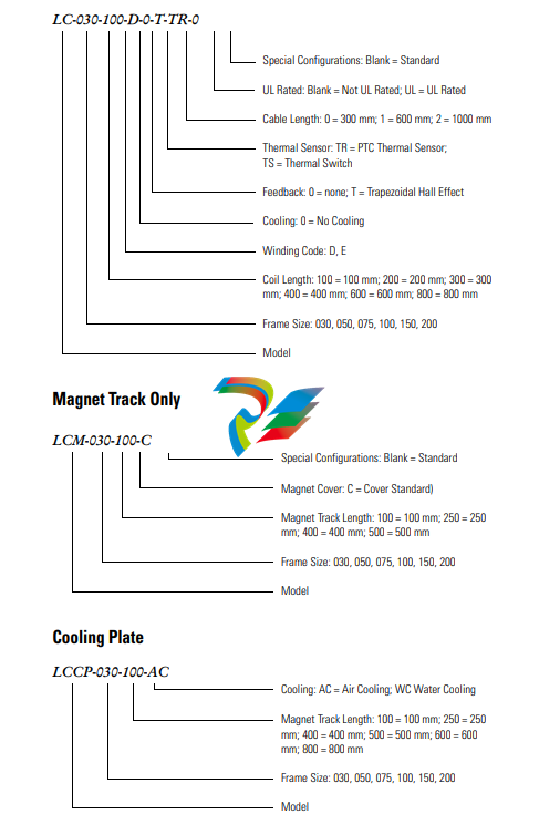
Identifying the Linear Motor
Type
Coil Assembly (example)
1. Ensure the mounting surface to which the magnet plate is to be attached
is clear of any and all foreign material. If necessary, stone the mounting
surface (acetone or methanol may be applied as cleaning agent).
Do not clean the surface using abrasives!
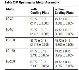
4. Position the moving slide to the end of travel that you wish the cable to
exit. Making sure that the mounting face of the motor coil is clean and
free of burrs, install the motor under the slide. Select a M5 x 0.8 bolt
with a length that extends through the slide by 12 mm minimum, but
not more then 20 mm. Tighten snugly for now, bolts will be torqued
once installation is complete.
5. On the opposite end of the base, install the first magnet plate using M5
x 0.8 and 16 mm long SHCS. Non-magnetic tools and hardware
(beryllium copper, 300 series stainless steel, etc.) should be use. If not
available proceed with care since magnetic items will be attracted to the
magnet plates. Do not tighten bolts at this time. Install additional
magnet plates by placing them on the base and sliding towards the
previous install plate. Orient the plates such that the alignment holes are
toward the same side. This will ensure proper magnet polarity.
6. Move the slide, which you previously mounted motor coil to, over the
magnet plate. There may be some resistance while moving onto the
plate, this is normal. Measure the gap between the motor and magnet
using plastic shim stock. The gap should be 0.79 mm (0.031 in.) to
1.70 mm (0.067 in.). If gap is too large, add appropriate brass or stainless
steel shim between motor and slide. If gap is to small, machine the slide
or place shims under the bearing pucks.
7. Once the motor is gapped properly, install the remaining magnet plates.
8. The final alignment of the magnet plates are done with an aluminum
straight edge, and the alignment tool that was supplied with the magnet
plates. Slightly loosen the magnet plate mounting bolts, but not the ones
that are covered by the motor coil. Place the alignment tool in the holes
on each of the plates, this will properly position the pitch of the plates.
Align the edges of the plate with the aluminum straight edge and tighten
the bolts
9. Position the slide over the complete sections and continue aligning the
remainder of the plates.
10. If the area where the magnet plates are to be installed does not allow you
to use a straight edge describes above, an alternate method of aligning
plates can be done. Space the plate by using a 0.020 plastic shim between
the magnet plates, tighten the bolts, and then remove the shim.
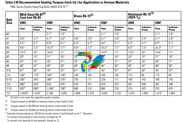
11. Once all the alignment is completed, torque all bolts to values listed in
the tables.When considering torque values for mounting hardware, take
into account the magnet plate, mounting surface and mounting
hardware. Per Table 2.N secure all assemblies in place using all
mounting holes.
ATTENTION
!
Remove alignment tool and make certain all magnet plate
mounting hardware is flush or below magnet surface to
prevent damage to the coil.
Motor/Hall Phasing and
Sequence
See Figure 2.15 for the standard phase and sequence relationship of the LC
series motors when phased in the specific motor direction. The Trapezoidal
Hall signals are used by a compatible three phase brushless servo drive to
perform electronic commutation. Two types of servo drive Hall-based
commutation techniques are possible, Trapezoidal Hall Mode and Encoder
(Software/Digital) Mode with Trapezoidal Hall start-up. Note: For optimal




.jpg)
.jpg)
.jpg)


.jpg)
.png)
.jpg)
.jpg)
_lVjBYb.jpg)
.jpg)
.jpg)
.jpg)
.jpg)
.jpg)
.jpg)
.jpg)
.jpg)
.jpg)
.jpg)
.jpg)
.jpg)
.jpg)
.jpg)
.jpg)
.jpg)
.jpg)
.jpg)

.jpg)
.jpg)
