The ISA112 series of SCADA systems standards, currently in development, will provide guidance on how these various facilityowner SCADA design guidelines, templates and examples can be organized into a set of SCADA design standards. A committee of 300 automation professionals are working on the ISA112 standards and Part 1 is on track to be published in late 2024. A draft SCADA Systems Management Lifecycle diagram is downloadable now; excerpts are shown in Figures 2 and 3.
Background stage
Once the design team has been selected, the next step is to conduct a detailed survey of the existing conditions and legacy systems that must be incorporated (or replaced) by the new design. If it is a legacy site, this includes gathering historical documentation about the facility. From a SCADA perspective, this should include, at a minimum, a set of up-to-date piping and instrumentation diagrams (P&IDs), site layouts, floor plans and electrical drawings.
Ideally, electrical drawings will include not only power distribution drawings, but also drawings for programmable logic controller (PLC) panels, controller panels, motor starters, field wiring, input/output (I/O) signals, control system networks and any other control system wiring. Some utilities will even pay a third-party engineering firm to make a set of as-found electrical drawings, P&IDs and floor layouts, so these can be provided to the main project’s design team as part of the background information.
Once the design team has a good understanding of the project scope and background information, they will develop a short report that outlines their proposed design solution. This is typically called the “design brief,” which can range from a few pages to more than 100. The design brief usually includes conceptual drawings. Sometimes the design brief is referred to as the “conceptual design phase” or a “10% design."
From a SCADA perspective, the design brief must also include a short section about the proposed automation hardware and how it will work.
Preliminary design
After the design brief has been reviewed by the utility and relevant stakeholders, the next step is to carry out the preliminary design. This stage is often called the “30% design.” There is usually a considerable amount of design effort that must be spent at this stage, as this is when the overall project plan is fully developed and the important question of “Will it all work?” must be sorted out. The preliminary design stage should result in a preliminary design report that outlines the various features of the proposed design and the rationale behind them, and it should be accompanied by a set of preliminary drawings.
Figure 3: Recommended SCADA installation and commissioning work processes. (Source: ISA112 SCADA Systems standards committee). From a SCADA perspective, the preliminary design package should include a high-level diagram of the automation equipment to be used, a process flow diagram, floor plans and a list of hazardous areas that may require equipment with special electrical ratings. Many preliminary designs also include preliminary lists of electrical loads, pumps, major valves and instruments. Preliminary design is also when SCADA “proofof-concept” testing should be carried out as needed on proposed automation equipment.
Detailed design phases
Once the preliminary design has been reviewed by the utility and feedback has been gathered, the next step is to proceed to detailed design. A commonly used progression of detailed design stages is 50%, 70%, 90% and construction ready. The decision of how many detailed design stages will be used and if supporting technical memos are to be developed will have been defined in the ToR at the start of the project.
At the end of each detailed design stage, an increasingly detailed package of drawings and specifications will be provided to the utility for review. At each design phase, the number of drawings and length of the specifications will increase as well. For example, at 50% design, the specifications section will usually only consist of a table of contents, whereas at 90%, it is not uncommon for a specifications section to consist of hundreds, if not thousands, of pages organized into numbered sections.
The SCADA team’s role during detailed design
From a SCADA perspective, the main goal during detailed design is to ensure that all the various aspects of the design have been properly coordinated with each other, and that the utility’s SCADA design standards are being followed. The overall process systems, and the SCADA system that controls and monitors them, will only be able to function effectively if all the various aspects of the design have been well designed, coordinated and sized properly for all operating modes.
Operating modes include startup, shutdown, online, offline, normal operation and abnormal situations. Thus, both the utility’s and the design team’s SCADA staff need to be able to review all the drawings and specs together, not just the SCADA-specific sections, so they can check the overall design coordination.


 HIMA K1412B PLC Module
 HIMA K9202B PLC Module
 IS200VTCCH1CBD GE Speedtronic Turbine Control PCB board
 TRICONEX 4200 Digital Output Module
 DEIF SCM-1 PCB CARD Module
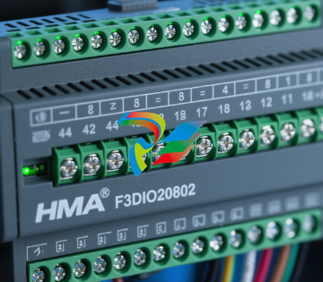 HIMA F3DIO20802 controller plc F3DIO20802
 HIMA B5233 PLC Module
 HIMA B5322 PLC Module
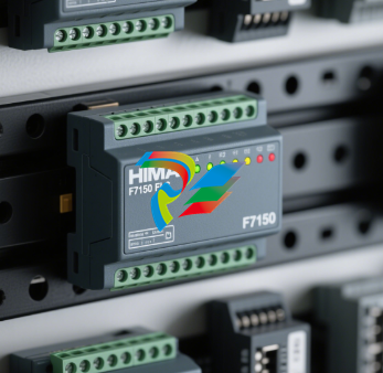 HIMA F7150 PLC Module
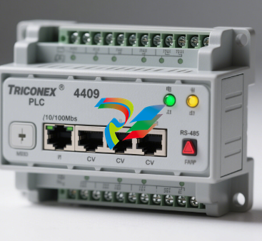 HIMA Z7308 PLC Module
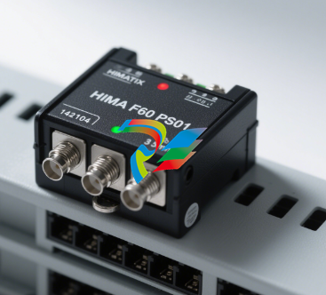 HIMA F60 PS01
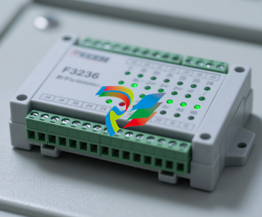 TRICONEX 4409 PLC Module
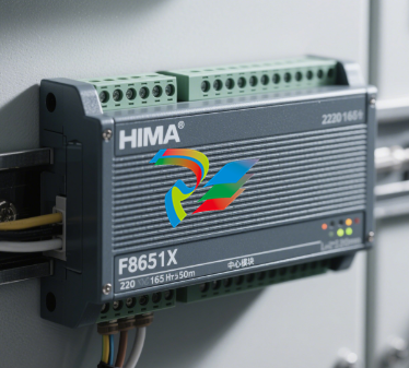 F8651X HIMA Central module F8651X
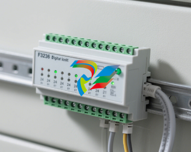 F3236 DIGITAL INPUT MODULE
 HIMA-6E-B HIMA-6E-B Large System Controller
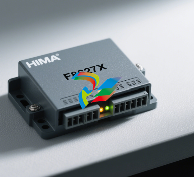 F8627X HIMA communication module F8627X
 HIMA P8403 PLC Module
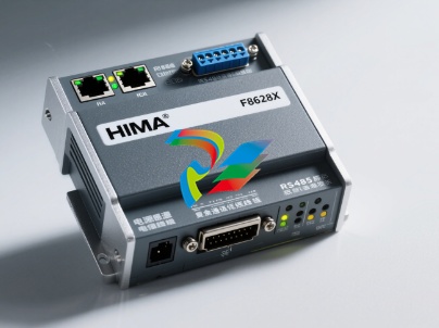 F8628X HIMA F8628X communication module
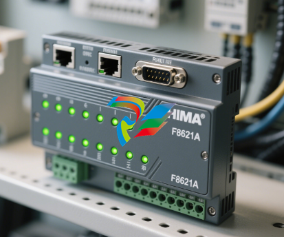 F8621A HIMA communication module
 IS200VRTDH1D GE Mark VI Printed Circuit Board
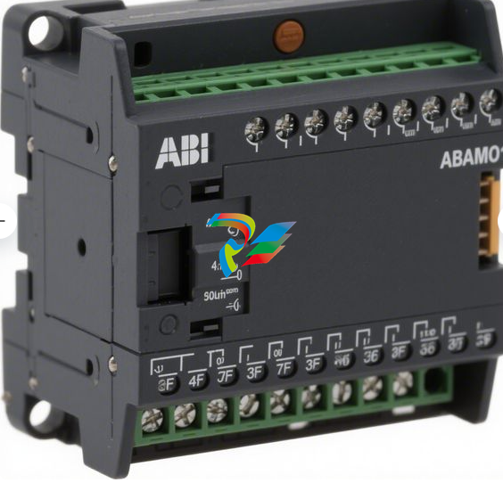 ABB NIAMO1 PLC Module
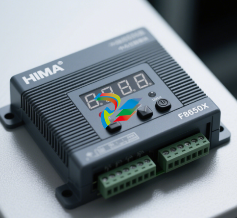 HIMAcard F8650X
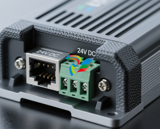 HIMA F8652 98465266 PLC Module
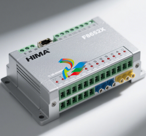 F8652X HIMA Central module
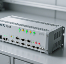 HIMA 62100
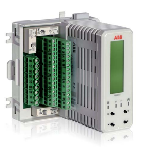 HIMA 99-7105233 B5233-1 NSMP
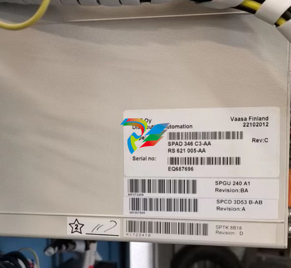 ABBSPAD 346 C3-AA
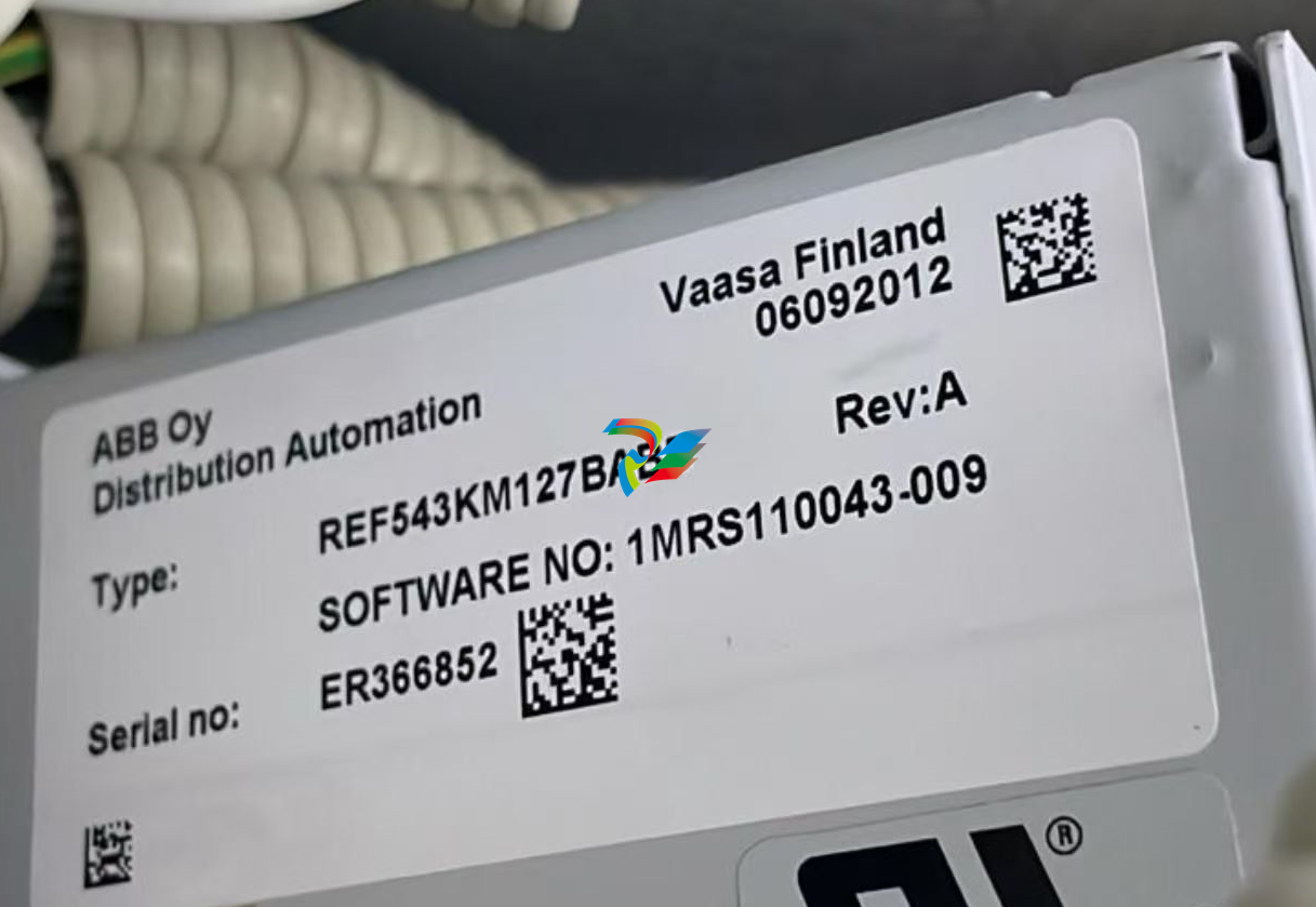 ABBREF543KM127BABB
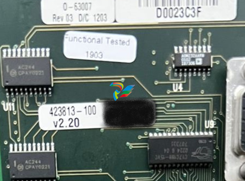 ABB 0-63007 M003742626
 Abb FET3251A0P1B3C0H2M
 ABB 3HAB8800-1
 ABB 3AUA266001B166
 ABB3HNM07686-1
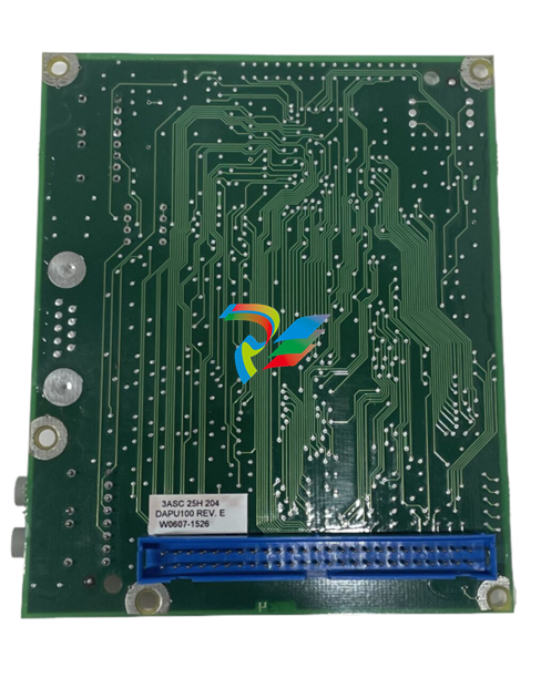 ABB PQF4-3 TAS
 Honeywell 30735863-502 - SWITCH
 Honeywell TK-CCR014 - REDUNDANT NET INTERFACE NEW ORIGINAL FREE EXPEDITED SHIPPING/
 Honeywell 51403165-400 - new 51403165400/
 Honeywell318-049-001 quot100 Batteries(Japan Liion2Ah14.8Wh)INTERMEC/ PR2,PR3 P/N
 Honeywell FC-PSU-UNI2450U - Power Supply
 Honeywell 965-0676-010 - WARNING COMPUTER SV
 Honeywell 51403519-160 - Module
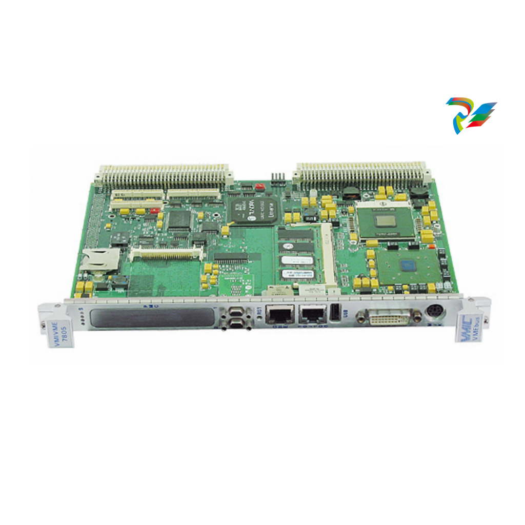 Honeywell 107843 - HOUSING CARBON FILE P/N NE COND # 11438 (4)
 Honeywell VR434VA5009-1000 - Brand new in box Condensing boiler valve DHL fast shipping
 Honeywell SPXCDALMFX - plc new FREE EXPEDITED SHIPPING/
 Honeywell BCM-PWS - BCM-ETH BCM-MS/TP BCM-MS/TP Network controller setFedEx or DHL
 Honeywell IWS-1603-HW - 90-250VAC 1.0A UNMP
 Honeywell 51304386-150 - MEASUREX Factory Packed
 Honeywell CC-IP0101 - Profibus Gateway Module
 Honeywell 50071726 - St 800 Series Pressure Transmitter Remote Diaphragm 11-42VDC
 Honeywell 621-2150 - / 6212150 (NEW NO BOX)
 Honeywell 80360206-001 - USED YAMATAKE CLI BOARD
 Honeywell BMDX001A-001 - ACCURAY / BOARD BMDX001A001
 Honeywell XCL8010A - New CPU Controller.
 Honeywell PGM-7320 - 1PCS NEW Rae Systems MiniRAE 3000 Portable VOC Monitor#XR
 Honeywell BK-G40 - U65 *FULL INSTALLATION* Gas Meter 3?± Inlet/Outlet Spool NEW UNUSED
 Honeywell DM106-0-B-00-0-R-1-00000-000-E0 - DPR100 250V NSNP
 Honeywell KFD840 - PRIMARY FLIGHT DISPLAY CORE PN: 066-01206-0104
 Honeywell 51401914-100 - 51400996-100
 Honeywell TK-PRS021 - Module Via FEDEX/DHL
 Honeywell C7012A1145 - 1PC New UV Flame Detector Expedited Shipping
 Honeywell OV210 - Baxter Bakery Oven Igition Control. For DRO. 00-616973 NEW
 Honeywell 51304431-125 - 1PC New /51304431125 1 year warranty#XR
 Honeywell DPCB21010002 - Tata Printed Circuit Board Rev: 0
 Honeywell 001649-M5T028 - Tata Printed Circuit Board Rev: 0
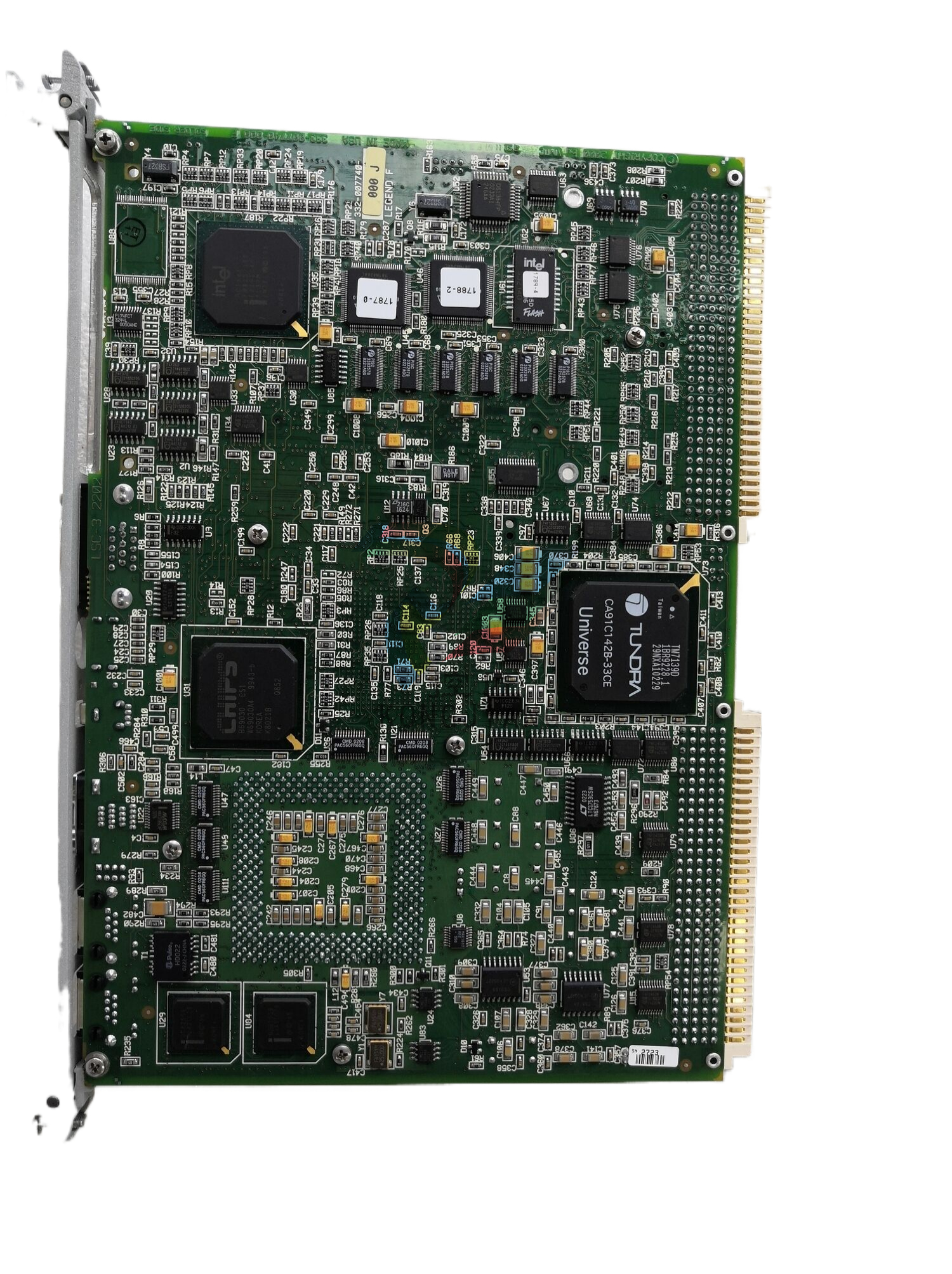 Honeywell XF523-A - / XF523A (NEW IN BOX)
 Honeywell 2MLR-AC22 - " 2mlr-dbsf,2mlf-ad4s,2mlf-dc4s,2mlr-ac22 Rack"
 Honeywell 9436610 - MEASUREX NSMP
 Honeywell RT10A-L0N-18C12S0E - RT10A.WLAN.IN.6803.CAM.STD.GMS
 Honeywell TK-FTEB01 - PCL module Brand New Fast Shipping By DHL
 Honeywell 8694500 - Measurex Control Processor Module
 Honeywell XNX-UTAI-RNNNN - NEW Universal transmitter DHL Fast delivery
 Honeywell SPXCDALMFX - plc new One Year Warranty #
 Honeywell XCL8010A - / XCL8010A (USED TESTED CLEANED)
 Honeywell 51198801-100 - NEW CPU INTERFACE BOARD UPGRADE KIT UPIU 51306154-100
 Honeywell 8C-TCNTA1 - C300 system card brand new Fast Shipping
 Honeywell ANT67A - TCAS Antenna 071-01548-0100 w/ October 2023 Repaired 8130
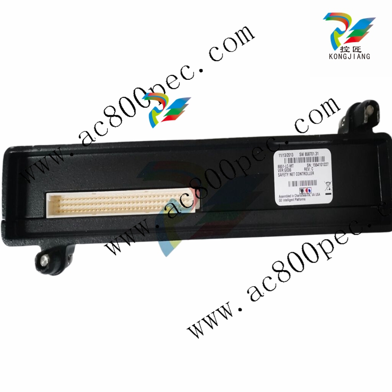 Honeywell R7247C1001 - 2-4SECS NSMP
 Honeywell ALI-80A - Collins Encoding Altimeter - P/N 622-3975-011 - Tested 8130 -Serviceable
 Honeywell J-HAM10 - NSNP
 Honeywell 114M4910-6 - PISTON ASSY PN NS COND 12037
 Honeywell 510STR12D21A-B77P - NSNP
 Honeywell QPP-0001 - FSC QUAD PROCESSOR PACK QPP MODULE CC V1.4
 Honeywell STD830-E1HS4AS-1-A-ADB-11C-B-21A0-00-0000 - 4500PSI NSNP
 Honeywell 900C75-0560 - NEW HC900 Controller module FedEx DHL Fast delivery
 Honeywell 942-M96-M - plc new FREE EXPEDITED SHIPPING
 Honeywell TK-IAH161 - 1PC New ANALOG INPUT TKIAH161 Expedited Shipping
 Honeywell 82408667-001 - NEW MEMORY BOARD ROM/RAM 82408667001
 Honeywell TK-FTEB01 - NEW IN BOX FTE BRIDGE Brand New Fast Shipping FedEx or DHL
