
GEInstallation and Maintenance Manual
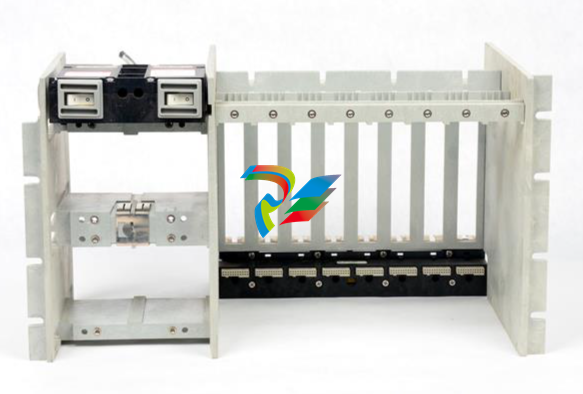
The Earthing Module is a full-height module that provides a low resistance
connection (must be less than 1 Ω) from the 3500 rack to the plant’s intrinsically
safe earth ground. The module operates in conjunction with the 3500 internal
zener barrier I/O modules. Your application will require 1 Earthing Module per rack
when internal barrier I/O modules are used.
2.4 Standard Rack Relay Options
You can configure the standard (or non-TMR) 3500 rack to have individual relays,
bussed relays, or a combination of individual and bussed relays.
2.4.1 Individual Relays
A rack with individual relays contains 1 or more relay cards for each monitor
module. You can configure the monitor and relay modules within a 3500 rack in
many ways.
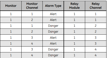
Example 1: The application uses 1 relay module 1 monitor module.
Table 2-1: 1 Relay Module Used With 1 Monitor Module
2.5 Intrinsic Safety — The 3500 Internal Barrier System
To provide Intrinsically Safe (IS) vibration and process variable monitoring, the
3500 system has a range of I/O modules with internal zener barriers. When you
install these modules in a 3500 rack with a 3500/04-01 Earthing Module, they
provide an integrated solution for explosion protection for approved Bently
Nevada transducer systems that are located within all classifications of
hazardous areas (surface industries other than mining).
2.5.1 3500 Internal Barrier System Restrictions
• You must install 1 earthing module in each rack in the internal barrier
system. The earthing module occupies 1 slot position in the rack when it
uses Internal Barrier I/O modules.
• You must change the grounding configuration of the 3500/15 Power
Supplies from the default factory setting. See the 3500/15 Operation and
Maintenance Manual (PN 129767-01) for instructions.
• You must isolate any RS-232 connection to any 3500 module. Monitors
that support RS232 connections include Rack Interface Modules,
Communication Gateways, and the 3500/95 PC Display. See the 3500/20
Operation and Maintenance Manual (PN 129768-01) for instructions. This
restriction does not apply to RS422 and RS485 connections to the rack.
Monitors that support RS422 and/or RS485 connections include the
3500/20, 3500/90, 3500/92, 3500/93, and 3500/95.
• You must not use the 3500/94 VGA Display in internal barrier systems.
• You must not use bussed transducers, as internal barrier systems do not
allow bussed transducers. See the TMR section of this manual for more
information.
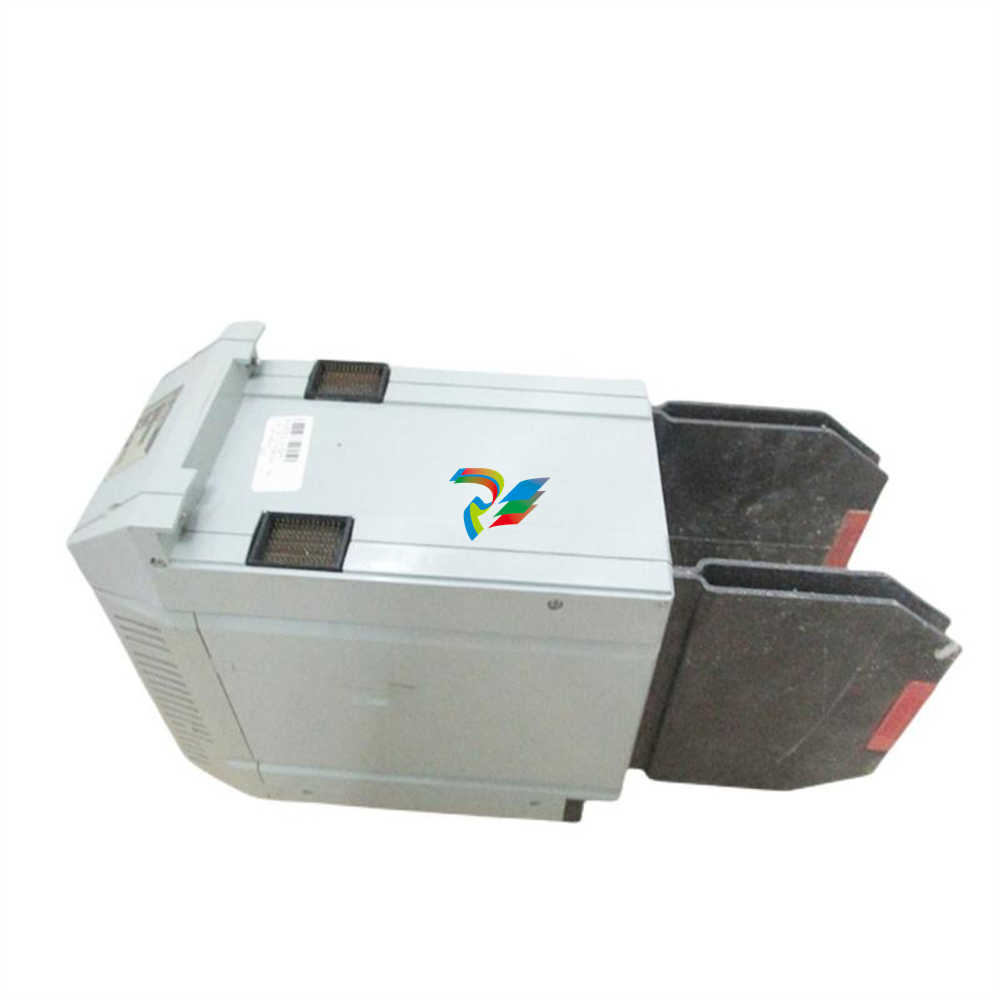
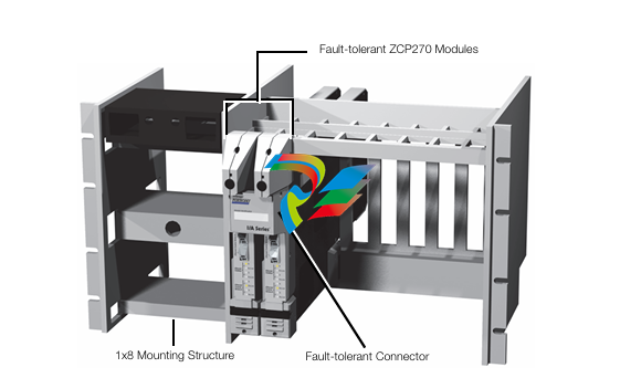
2.5.2 3500 Internal Barrier System Features
• The earthing module supports dual IS Earth connections for cables with
cross-sectional areas up to 10 mm2. This module lets you test IS Earth
continuity online.
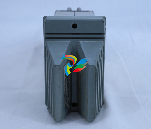
• The design of the internal barrier I/O modules provides the 2 inches (50
mm) of separation required between safe and hazardous area field wiring.
• The connectors for safe areas and hazardous areas have different field
wiring colors (green for safe and blue for hazardous) and connector
pitches. This helps to avoid incorrect field wiring installation.
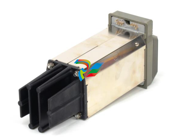
• Quick connect/disconnect connectors simplify field wiring installation and
removal.
4.3 Replacing Modules
When replacing modules, whether main or I/O, you need not remove power from
the rack if the following procedures are followed. Refer to applicable steps in the
procedures above for removing or installing a module.
4.3.1 Main Modules
This assumes that you will replace only the main module of a monitor or power
supply. Before you remove any module, refer to the applicable manual to see how
this may affect rack behavior, and to identify any special handling requirements
that you may require for personal safety.
1. If necessary, upload and save the configuration of the module to be
replaced.
2. Remove the main module from the rack.
3. Install the new main module into the rack.
4. If necessary, configure the new main module.
5. Verify operation.
4.3.2 I/O Modules
This assumes that you will replace only the I/O module of a monitor or the PIM of
a power supply. Before you remove any module, refer to the applicable manual to
see how this may affect rack behavior, and to identify any special handling
requirements that you may require for personal safety.
1. If necessary, upload and save the configuration of the module to be
replaced.
2. Remove the main module from the rack.
3. Remove the field wiring from the I/O module.
4. Remove the old I/O module from the rack.
5. Install the new I/O module into the rack.
6. Connect the field wiring to the new I/O module.
7. Install the main module into the rack.
8. If necessary, re-configure the main module.
9. Verify operation
5.1 General Maintenance Instructions
You cannot repair the boards and components inside of 3500 modules in the field.
3500 rack maintenance consists of testing module channels to verify that they
-
 GE SR745-W2-P1-G1-HI-A-L-R-E Feeder protection relay
 -
 GE IS230TNDSH2A Discrete Output Relay Module Brand
 -
 GE Fanuc IS200TDBSH2ACC Mark VI Terminal Board Brand
 -
 GE PMC-0247RC-282000 350-93750247-282000F Disk Drive
 -
GE PMC-0247RC-282000 350-93750247-282000F Disk Drive
-
 GE VMIVME-1150 Serial Communications Controller
 -
 GE VMIVME-5576 Fiber-Optic Reflective Memory with Interrupts
 -
 GE VMIC Isolated Digital Output VMIVME-2170A
 -
 GE MULTILIN 760 FEEDER MANAGEMENT RELAY 760-P5-G5-S5-HI-A20-R-E
 -
 GE IS200AEPAH1BKE IS215WEPAH2BB Printed circuit board
 -
 GE IS210BPPCH1A Mark VIe I/O Pack Processor Card
 -
 GE IS220PRTDH1A 336A4940CSP6 High-Performance RTD Input Module
 -
GE IS220PDIAH1BE 336A5026ADP4 Discrete Input Module
-
 GE IS420ESWBH3A IONET Switch Module
 -
 GE 516TX 336A4940DNP516TX 16-port Ethernet switch
 -
 GE EVMECNTM13 Embedded control module
 -
 GE EVPBDP0001 EVPBDP032 control module
 -
 GE Hydran M2-X Enhanced Monitoring with Extended Sensor Life
 -
 GE UR6CH Digital I/O Module
 -
 GE IC695CPU315-CD Central processing unit
 -
 GE 531X305NTBAMG1 DR Terminal Board
 -
 GE 531X305NTBALG1 NTB/3TB Terminal Board 531X Series
 -
 GE 531X305NTBAJG1 NTB/3TB Terminal Board.
 -
 GE 531X305NTBAHG1 NTB/3TB Terminal Board 531X
 -
 GE 531X305NTBAEG1 is a PCB that functions as a DR terminal board.
 -
General Electric 531X305NTBACG1 NTB/3TB Terminal Board 531X
-
 GE Digital Energy D20 Analog Input Module
 -
 GE 94-164136-001 main board Control board
 -
 GE 269 PLUS-D/O-100P-125V Digital motor relay
 -
 GALIL DMC-9940 High-performance motion controller
 -
 FUJI NP1BS-08 base plate
 -
 FUJI NP1Y32T09P1 Transistor drain type digital output module
 -
 FUJI NP1Y16R-08 Digital Output Module
 -
 FUJI NP1X3206-A High-speed digital input module
 -
 FUJI NP1AYH4I-MR current output module
 -
 FUJI NP1S-22 Power module redundancy
 -
 FUJI RPXD2150-1T servo drive module
 -
 FUJI FVR008E7S-2UX Ac frequency converter
 -
 FUJI Ac frequency converter FVR008E7S-2
 -
 FUJI FVR004G5B-2 Small general-purpose frequency converter
 -
 FUJI A50L-2001-0232 Industrial control module
 -
 FUJI A50L-001-0266#N High-performance servo amplifier
 -
 Honeywell FS7-2173-2RP Gas sensor
 -
 Honeywell 10106/2/1 Digital Input Module in Stock
 -
 FRCE SYS68K CPU-40 B/16 PLC core processor module
 -
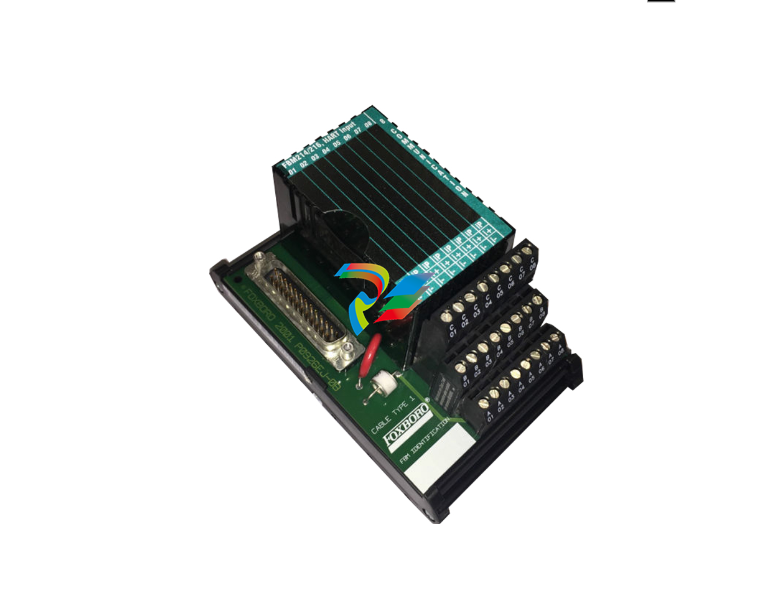
 Foxboro FBM I/O cards PBCO-D8-009
 -
 Foxboro AD916AE Digital Control System (DCS) Module
 -
 GE SR750-P5-G5-S5-HI-A20-R-E Multilin Relay
 -
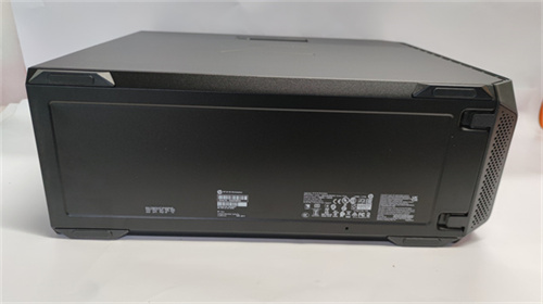
.jpg) FOXBORO H90 H90C9AA0117S Industrial Computer Workstation
FOXBORO H90 H90C9AA0117S Industrial Computer Workstation -
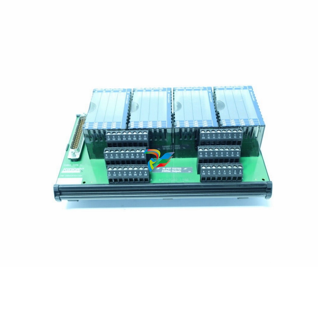
.jpg) FOXBORO RH928AW | I/A Series Relay Output Module
FOXBORO RH928AW | I/A Series Relay Output Module -
.jpg) Foxboro N-2AX+DIO Multi-functional input/output module
Foxboro N-2AX+DIO Multi-functional input/output module -
 Foxboro RH924WA FCP280 Fiber Optic Network Adapter
 -
 FOXBORO H92 Versatile Hardware Component In
 -
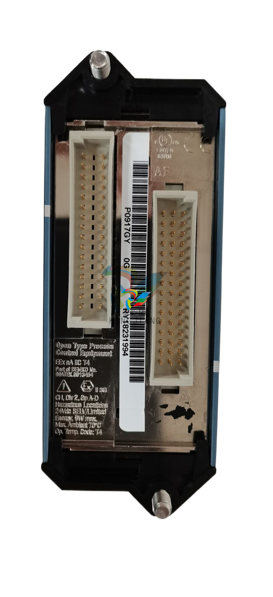
 Foxboro FBM218 P0922VW HART® Communication Redundant Output Interface Module
 -
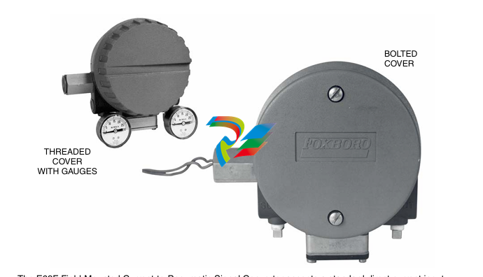
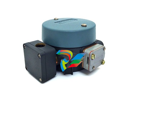 Foxboro E69F-TI2-J-R-S E69F Series Current-To-Pneumatic Signal Converter
 -
 Foxboro E69F-BI2-S Converter
 -
.jpg) Foxboro H92A049E0700 The host of the DCS control station
Foxboro H92A049E0700 The host of the DCS control station -
 Foxboro H90C9AA0117S Industrial computer workstation
 -
 Foxboro RH101AA High-performance industrial control module
 -
 Foxboro P0922YU FPS400-24 I/A Series Power supply
 -
.png) FOXBORO P0973LN Chassis-based managed switch with independent power supply
FOXBORO P0973LN Chassis-based managed switch with independent power supply -
.jpg) FOXBORO P0926PA Input/output module
FOXBORO P0926PA Input/output module -
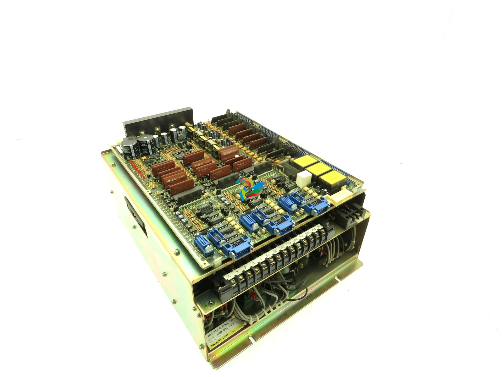 Fanuc A06B-6050-H402 3 AXIS ANALOG AC SERVO DRIVE
 -
.jpg) FOXBORO L0130AD L0130AE-0H Power module group
FOXBORO L0130AD L0130AE-0H Power module group -
_lVjBYb.jpg) FOXBORO 0399085B 0303440C+0303458A Combination Control Module
FOXBORO 0399085B 0303440C+0303458A Combination Control Module -
 FOXBORO SY-0399095E (SY-0303451D+SY-0303460E) Process control board
 -
.jpg) FOXBORO 0399071D 0303440C+0303443B Input/Output (I/O) Module
FOXBORO 0399071D 0303440C+0303443B Input/Output (I/O) Module -
.jpg) FOXBORO RH924UQ Redundant Controller module
FOXBORO RH924UQ Redundant Controller module -
 FFOXBORO E69F-TI2-S current pneumatic converter
 -
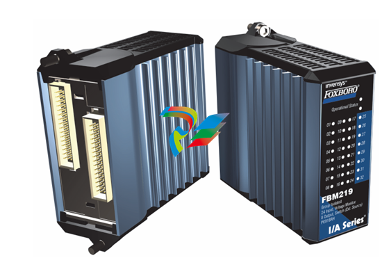 FOXBORO FBM219 RH916RH Discrete I/O Module
 -
 FOXBORO FBM227 P0927AC Module
 -
.jpg) FOXBORO 0399144 SY-0301059F SY-1025115C/SY-1025120E I/O module
FOXBORO 0399144 SY-0301059F SY-1025115C/SY-1025120E I/O module -
.jpg) FOXBORO SY-60399001R SY-60301001RB Industrial Control Module
FOXBORO SY-60399001R SY-60301001RB Industrial Control Module -
 FOXBORO 0399143 SY-0301060R SY-1025115C SY-1025120E Combined control board
 -
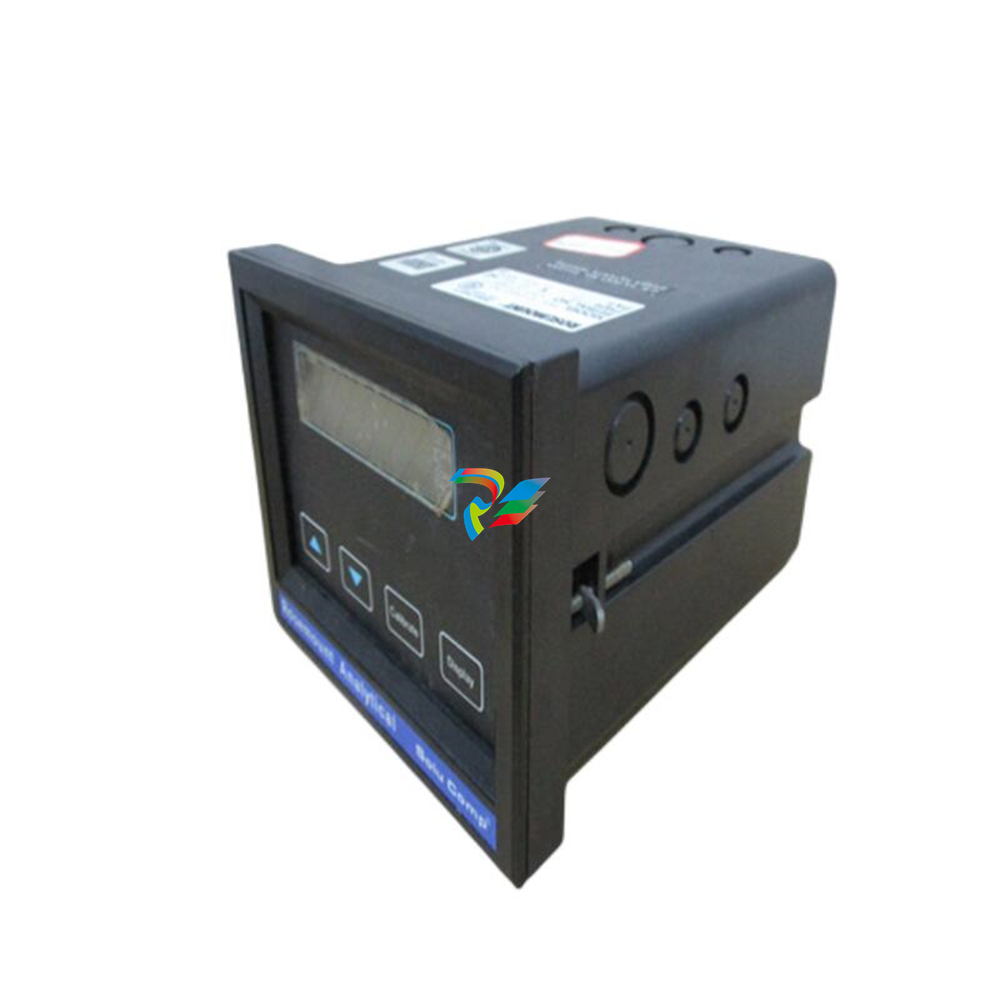
 FOXBORO 873EC-JIPFGZ electrodeless conductivity analyzer
 -
 FOXBORO P0916PH (High-density HART I/O Module)
 -
 FOXBORO 870ITEC-AYFNZ-7 Intelligent Electrochemical Transmitters
 -
 FOXBORO Compact FBM240. Redundant with Readback, Discrete
 -
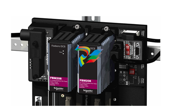 FOXBORO FBM208/b, Redundant with Readback, 0 to 20 mA I/O Module
 -
 FOXBORO FBM201e Analog Input (0 to 20 mA) Interface Modules
 -
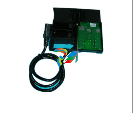
.jpg) FOXBORO P0916WG Terminal cable
FOXBORO P0916WG Terminal cable -
 FOXBORO P0926MX 2-Port Splitter
 -
.jpg) FOXBORO AD908JQ High-Frequency Module
FOXBORO AD908JQ High-Frequency Module -
.jpg) FOXBORO AD916CC Processor module
FOXBORO AD916CC Processor module -
 Foxboro DCS FBM206 Pulse Input Module
 -
 FOXBORO FBM216 HART® Communication Redundant Input Interface Module
 -
 Foxboro p0903nu 1×8 unit sub-component module
 -
 Foxboro P0911SM Industrial control module
 -
 Foxboro CM902WM I/O module
 -
 Foxboro CM902WL Power module
 -
 Foxboro P0972VA Industrial Control Module
 -
 Foxboro Z-Module Control Processor 270 (ZCP270)
 -
 Foxboro PO916JS 16-channel terminal block module
 -
 Foxboro PO911SM High-performance digital/analog input/output module
 -
 Foxboro P0972PP-NCNI Network Interface Module
 -
.jpg) FOXBORO P0971QZ controller module
FOXBORO P0971QZ controller module -
 FOXBORO P0971DP Thermal resistance input/output module
 -
 FOXBORO P0970VB Cable connector
 -
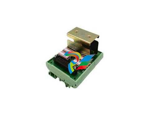
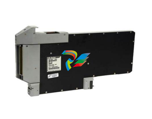
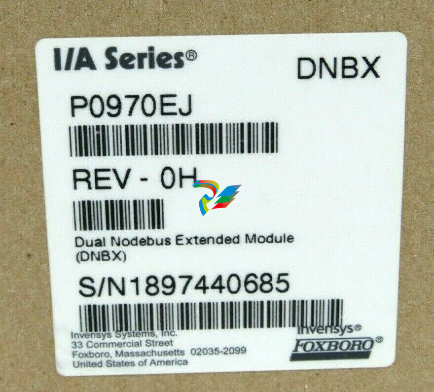 FOXBORO P0970EJ-DNBX Dual-node bus expansion module
 -
 FOXBORO P0970BP Redundant power supply system
 -
.jpg) FOXBORO P0970BC-DNBI DeviceNet bus interface module
FOXBORO P0970BC-DNBI DeviceNet bus interface module -
.jpg) FOXBORO P0961FX-CP60S Main control CPU module
FOXBORO P0961FX-CP60S Main control CPU module -
.jpg) FOXBORO P0961EF-CP30B Network Interface Unit
FOXBORO P0961EF-CP30B Network Interface Unit -
.jpg) FOXBORO P0961CA Optical fiber local area network module
FOXBORO P0961CA Optical fiber local area network module -
.jpg) FOXBORO P0961BD-GW30B gateway processor module
FOXBORO P0961BD-GW30B gateway processor module -
.jpg) FOXBORO P0961BC-CP40B/I/A Series high-performance control processor module
FOXBORO P0961BC-CP40B/I/A Series high-performance control processor module -
FOXBORO P0960JA-CP40 High-performance control processor
-
FOXBORO P0926TM Control module
-
 FOXBORO P0916BX Termination Assembly
 -
.jpg) FOXBORO P0916AE P0916AG P0916AW Thermal resistance input type DCS card module
FOXBORO P0916AE P0916AG P0916AW Thermal resistance input type DCS card module -
 FOXBORO P0916AC FOXBORO distributed control system (DCS) compression terminal assembly
 -
.jpg) FOXBORO P0912CB High-performance interface module
FOXBORO P0912CB High-performance interface module -
.jpg) FOXBORO P0911VJ Thermal resistance input output module
FOXBORO P0911VJ Thermal resistance input output module -
.jpg) FOXBORO P0911QH-A High-precision module
FOXBORO P0911QH-A High-precision module -
 FOXBORO P0911QB-C P0911QC-C Thermal resistance input/output module
 -
 FOXBORO P0904BH P0904FH P0904HB Distributed Control system (DCS) module
 -
 FOXBORO P0903ZP P0903ZQ Embedded System Debugging Module
 -
 Foxboro P0903ZL P0903ZN Industrial power module
 -
 Foxboro P0903ZE I/A Series Fieldbus Isolator Module
 -
 FOXBORO P0903NW Industrial Control Module
 -
.jpg) FFOXBORO P0903NQ Industrial power module
FFOXBORO P0903NQ Industrial power module -
 FFOXBORO P0903AA Control Module
 -
 FOXBORO P0400DL Digital output module
 -
.jpg) FOXBORO P0400BJ Digital output module
FOXBORO P0400BJ Digital output module -
 FOXBORO GW30 industrial control module
 -
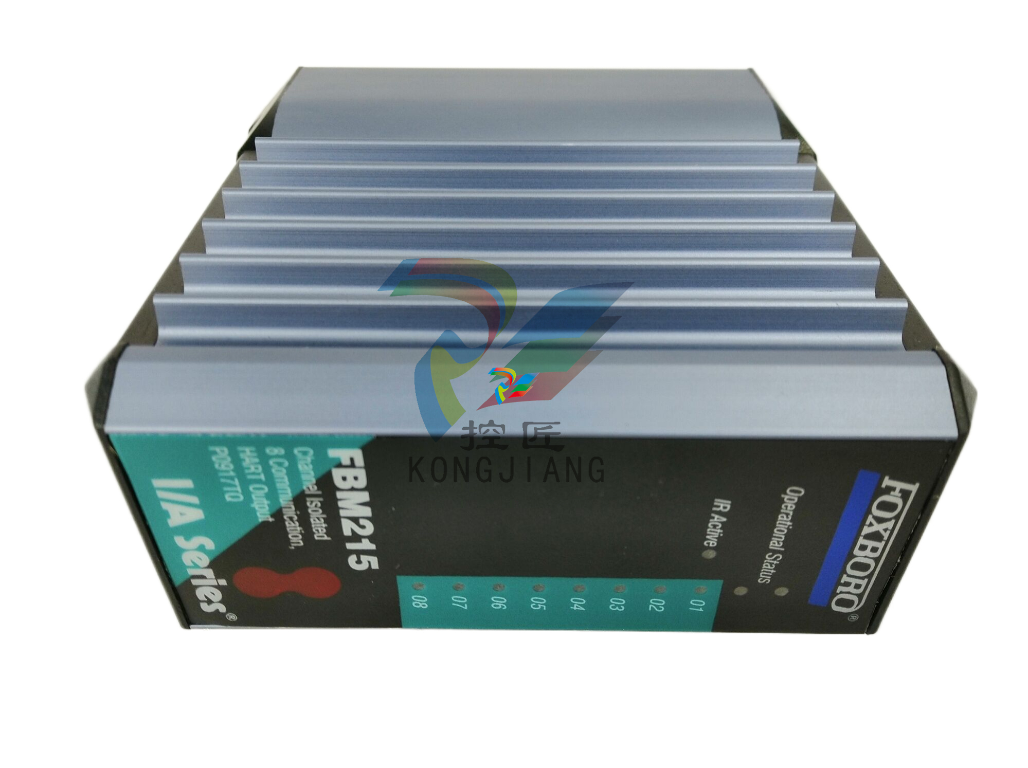
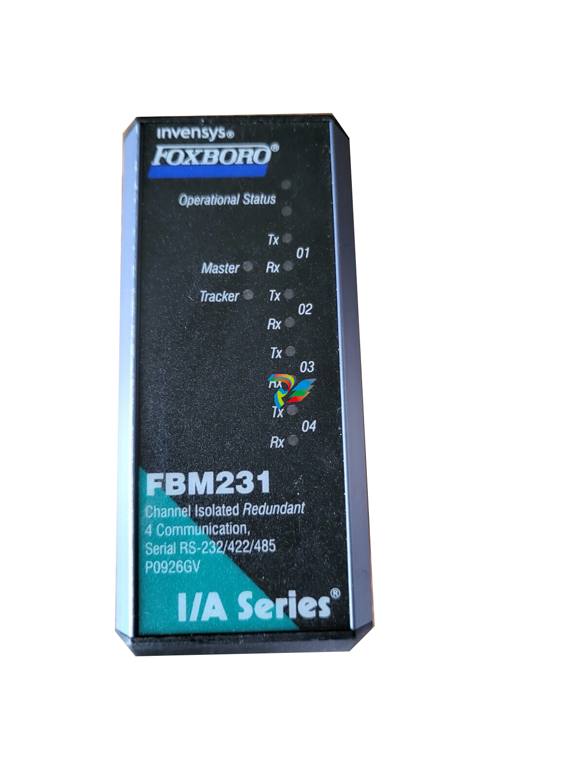 FOXBORO FBM231 Communication Output Module
 -
 FOXBORO Fieldbus Communications Module, FCM10Ef
 -
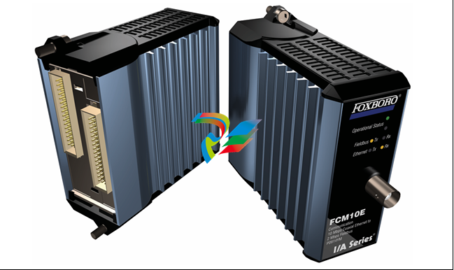 FOXBORO Fieldbus Communications Module, FCM10E


