
ABBDCS Thyristor Power Converters for DC Drive Systems 25 to 5150 A Operating Instructions DCS 600 MultiDrive
armature-circuit current since EMF control is active.
If the unit aborts the auto-tuning routine with the signal 15.02 = -1, the probable
cause of this can be read out of Parameter 6.02 and has to be eliminated as far
as possible (supply, switching sequence etc.).
Afterwards repeat the auto-tuning routine.
If necessary, perform manual balancing.
Switch OFF power!
Read out values of:
41.11 = ......... 41.12 = ......... 43.02 = ......... 43.03 = ............ 43.06 = .........
Use values of 41.11 and 43.06 from the first auto-tuning routine.
Re-activate the field unit used by entering:
a) 15.05 = 1
or
b) 15.05 = 2
and install the supply fuses removed before
2.5 Speed feedback balancing
Activate EMF speed feedback:
50.03 = CALC BY EMF
Select no field weakening mode:
15.06 = FIX
50.01 = Desired speed / or motor rating plate
Scale speed control circuit to maximum speed.
Switch ON power.
DANGER: System components now energized!
Start drive.
Increase reference value in LOCAL mode to 10 % of the maximum speed.
Drive should run up to 10 % of the rated voltage.
Continue with one of the following sections:
• Only when an analog tacho is being used!
• Only when an encoder (pulse encoder) is being used!
• Only when the EMF signal is being used as speed feedback!
Only when an analog tacho is being used!
Connect measuring instrument:
- to X3: 1... 3 or X1: 1... 3
+ to X3: 4 or X1: 4
Check to make sure that the tacho voltage does not exceed the input voltage range
selected with maximum speed.
Turn Potentiometer R2716 [on SDCS-CON-2 board] or R9 [on PS5311 board; if
SDCS-IOB-3 board is used with PS5311] to minimum (left-hand stop).The
measured value must have a positive sign; if necessary interchange tacho cables.
Stop the drive and switch OFF power!
50.03 = ANALOGUE TAC
Analog tacho is used for speed control.
Switch ON power.
DANGER: System components now energized!
Start drive.
Increase reference value in LOCAL mode to 10 % of the maximum speed.
Drive should run up to 10 % of the rated voltage.
Use Potentiometer R2716 [on SDCS-CON-2 board] or R9 [on PS5311 board] to
set the tacho voltage to 10 % of the maximum tacho voltage.
Stop the drive and switch OFF power!
Only when an encoder (pulse encoder) is being used!
3.07 = Content of pulse counter *)
If the shape of the curve corresponds to the diagram below, this means
the wiring is correct and the pulses will be correctly evaluated [see
also documentation entitled “Technical Data”, Chapter I/O boards].
*) This Parameter must be transmitted from the SDCS-CON-2 board to the SDCS-AMC-DC board!
Fig.: Curve shape of the encoder’s pulse counter for sense of rotation "forwards”
Switch OFF power, thus stopping the drive; drive coasts.
50.04 = Number of encoder pulses
As specified on the encoder’s rating plate
50.03 = CON- ENCODER
The encoder connected to the SDCS-CON-2 board is used for speed control.
Switch ON power.
DANGER: System components now energized!
Start drive.
Increase reference value in LOCAL mode to 10 % of the maximum speed
Drive should run at 10 % of the desired speed;
if possible, check with manual tacho.
Stop the drive and switch OFF power!
Only when the EMF signal is being used as speed feedback!
Drive should run at 10 % of the desired speed;
if possible, check with manual tacho.
Stop the drive and switch OFF power
Balancing the field supply unit and the EMF controller
When matching the field supply unit to the system conditions, differences in the procedures must be taken into account; these different procedures result from the operating
mode used. Only the work of that section has to be performed which deals with
the operating mode actually used in your system!
Constant field current control ⇒ Section 2.6.1
Field weakening control with setting range smaller than 1 : 1.5 ⇒ Section 2.6.2
Field weakening control with setting range larger than 1 : 1.5 ⇒ Section 2.6.3
2.6.2 Field weakening control with setting range < 1 : 1.5
CAUTION: Not permitted when Chapter 2.5 was quit with EMF control!
15.06 = EMF CON
Field weakening function activated
99.05 = Speed at field weakening point according to motor rating plate
41.19 = ? reference armature voltage scaled to Supply voltage
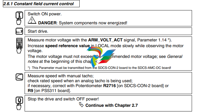
Switch ON power.
DANGER: System components now energized!
Start drive.
Measure motor voltage with the ARM_VOLT_ACT signal, Parameter 1.14 *).
Increase speed reference value in LOCAL mode slowly while observing the
motor voltage.
The motor voltage must not exceed the recommended motor voltage; see General
notes at the beginning of this chapter.
Check that field is being weakened.
Do not exceed the maximum motor speed permitted. When an analog tacho is being
used, the display at the CDP 312 panel is not yet necessarily correct.
The motor voltage must not exceed the recommended motor voltage; see General
notes at the beginning of this chapter.
If the field is not being properly weakened, or not being weakened at all, perform the
work of section "Field weakening control with setting range larger than 1 : 1.5” !
*) This Parameter must be transmitted from the SDCS-CON-2 board to the SDCS-AMC-DC board!
Measure speed with manual tacho;
check rated speed when an analog tacho is being used;
if necessary, correct with Potentiometer R2716 [on SDCS-CON-2 board] or
-
 Hirschmann RS20-1600M2T1SDAEHH03.1.02 Rail Switch
 -
 Hirschmann BRS30-24TX Industrial Rail Switch
 -
 Hirschmann RSPM20-4T14T1EV9HHS999.9.99 Managed Ethernet Switch
 -
 Hirschmann BELDEN RS40-0009CCCCSDAPHH09.0.14 / RS400009CCCCSDAPHH09014
 -
Hirschmann RS40 Rail Switch RS40-0009CCCCSDAE
-
 Hirschmann BELDEN RS30-0802T1T1SDAP / RS300802T1T1SDAP Fully Managed Layer 2 Compact Rail Switch
 -
 Hirschmann BELDEN RS20-0800M2M2SDAUHH / RS200800M2M2SDAUHH
 -
 Hirschmann EAGLE30-04022O6TT999SCCY9HSE3F Industrial Firewall Router Switch
 -
 Hirschmann RS20-1600T1T1SDAEHH09.0.14 RS20 Rail Mount Ethernet Switch
 -
 Hirschmann EAGLE0200T1T1TDDY90000HHE05.3.03 Industrial Security Router
 -
Hirschmann - BELDEN MIPP-AD-1L9P
-
 HIRSCHMANN RSPM20-4Z64Z6TV9HHS9 942 106-999 RAIL SAFETY SWITCH
 -
 HIRSCHMANN FIBEROPTIC MODULE FIP P/N: OZDFIPG3T
 -
 HIRSCHMANN RS20-1600M2M2SDAUHH Ethernet rack-mounted switch
 -
 HIRSCHMANN BELDEN RS20-0400T1T1SDAEHH04.0.01 / RS200400T1T1SDAEHH04001
 -
HIRSCHMANN MM2-4FXM3 MICE Media Module
-
HIRSCHMANN RS20-0800M2M2SDAE Industrial Ethernet Rail Switch
-
 Hirschmann RS20-2400T1T1SDAP / RS20-2400T1T1SDAPHH05.0.02
 -
 GE MLJ1005B010H00C MLJ Digital Synchromism Check
 -
 ALSTOM MICROTECH DX21-M2 Digital Excitation Controller
 -
HIRSCHMANN BRS20-1200ZZZZ-STCY99HHSES
-
 HIRSCHMANN MM3-4FXM2 MICE Media Module
 -
Hirschmann RSB20-0800T1T1SAABHH 8Port ENet Rail Switch RSB20
-
 Hirschmann MACH102-8TP Ethernet Switch
 -
 SAACKE DDZ-M marine steam pressure atomizer
 -
 SAACKE SKV-A marine rotary cup atomizer
 -
 SAACKE Seavis HMI05e
 -
 Kollmorgen MMC-SD-2.0-230 Servo Drive 100-240VAC 2KW 10A Output 3PH 100-240VAC
 -
 Kollmorgen Servo drive CR10550
 -
 Kollmorgen AKD-P01207-NACN-0054 Servo Driver
 -
 Kollmorgen S406M-CA-036 Servostar
 -
.png) Kollmorgen AKD-B02407-NAAN-0000 Digital Servo Drive
Kollmorgen AKD-B02407-NAAN-0000 Digital Servo Drive -
 Kollmorgen SERVOSTAR S406AM-CA Digital Servo Drive
 -
 KOLLMORGEN SERVOSTAR 603-AS SERVO AMPLIFIER_SERVOSTAR603AS_S60301
 -
Kollmorgen S700 Servo Controller (S70602-NANANA-NA)
-
 Kollmorgen MPK411 controller
 -
 KOLLMORGEN MMC-SD-1.3-460-D Smart Drive
 -
 KOLLMORGEN AKM21C-CKB2AA-00 / AKM21CCKB2AA00 Servomotor
 -
 BECKHOFF AX5106-0000-0200 | Digital Compact Servo Drives 1-channel
 -
 BECKHOFF C3620-0000 INDUSTRIAL COMPUTER (MOTORSHELVES)
 -
 Beckhoff EK1960-0000 TwinSAFE Compact Controller
 -
 Beckhoff C6930-0050 Control Cabinet Industrial PC
 -
 Beckhoff CP7711-0001-0030 Industrial Computer Detection
 -
 Beckhoff CX1001-0111 Embedded PC CPU Module
 -
 Beckhoff C6017-0020 | Ultra-compact Industrial PC
 -
 Beckhoff EK1322 | 2-port EtherCAT P junction with feed-in
 -
 Beckhoff CP2219-0010 Panel
 -
 BECKHOFF C6015-0020 ULTRA COMPACT INDUSTRIAL PC
 -
 BECKHOFF CX2030-0120/Standard CPU Module Embedded PC Windows PLC controller
 -
 Beckhoff CP7721-1090-0020 Panel PC
 -
 Beckhoff PC CPU Module CX5130-0175
 -
 Beckhoff C6920-0050 Control Cabinet
 -
 Beckhoff EL6631 EtherCAT 2-Port Communication Interface, Profinet RT Controller
 -
 Beckhoff CP6202-0001-0060 touch screen panel PC
 -
 Beckhoff CP3916-1002-0000 Multi-Touch Control Panel
 -
 Beckhoff EP1809-0021 | EtherCAT Box, 16-channel digital input, 24 V DC, 3 ms, M8Preferred type
 -
 Beckhoff CX8190 PLC Embedded Industrial PC Ethernet Controller
 -
 Beckhoff CX2100-0914 Power Supply for External
 -
 Beckhoff Automation CP6906-0001-0000 HMI
 -
 Beckhoff EP7342-0002 Module
 -
 Beckhoff CX1020-0112 / CX1100-0910 / CX1020-N010 / CX1100-0003 Windows CPU
 -
 Beckhoff EP7211-0034 EtherCAT Box 1 Channel Motion Interface
 -
 Beckhoff C6240-0030 Control cabinet Industrial PC
 -
 beckhoff motherboard CB1052-0004 CB1052-0004
 -
 Beckhoff AX2006-AS Servo Drive / Variable Frequency Drive
 -
BECKHOFF CP6207-0001-0020 NSMP
-
 Beckhoff C6930-1142-0060 Industrial Computer
 -
 Beckhoff FC7501-0000 interface card
 -
 Beckhoff CX5140-0175 Embedded PC PLC CPU CX5140 Industrial Controller
 -
 Beckhoff CP7802-1100-0010: High-End IP65 Control Panel with DVI/USB Extended Interface
 -
BECKHOFF CP3716-1058-0010 CONTROL PANEL
-
 Beckhoff AX8108-0000 Single-Axis Module
 -
 Beckhoff CU8851-0000 | USB extension, USB Extended 2.0 receiver box
 -
Beckhoff C6017-0030 | Ultra-compact Industrial PC
-
 Beckhoff CX1001-0120/CX10010120.cx1000-n001.cx1000-n000 System Overview
 -
 Beckhoff CPU Module CX5140-0155/4GB CPU Module
 -
 Beckhoff CP6533-0001-005: Built-in Panel PC with High-Definition Multi-Touch Control
 -
 Beckhoff EL5042 | EtherCAT Terminal, 2-channel encoder interface, BiSS® C
 -
 Beckhoff C6920-1080-0040: Premium Control Cabinet Industrial PC
 -
 Beckhoff C6920-0060 | Control cabinet Industrial PC
 -
 Beckhoff Embedded-PC CX5010-1121
 -
 Beckhoff CB3050-0010 Mainboard Motherboard
 -
 Beckhoff PLC module CX1020-0000 Basic CPU module (service phase)
 -
 Beckhoff CP7812-1056-0010 15" Multitouch Display Control Panel
 -
 Beckhoff CX5120-0115 /2GB Controller Module
 -
 Beckhoff CP7201-1000-0000 Industrial Panel PC
 -
 Beckhoff Servo Motor AM8061-0JH1-0000
 -
 BECKHOFF CP6503-0001-0050 Built-in Panel PC
 -
Beckhoff CP3919-0010 Display G190ETN01.2 19" PCT V04. Multi-touch Control Panel
-
 Beckhoff CX5110-0112-9020/000368201 Embedded PC Intel Atom Processor
 -
 Beckhoff AX8206-0000 Dual-Axis Module
 -
Beckhoff Nail Operating Terminal CP7032-1031-0010
-
Beckhoff AM8042-0EH1-0000 Servomotor 4.10 Nm (M0), F4 (87 mm)
-
 Beckhoff EK9300 Beckhoff CPU Module
 -
Beckhoff CP3224-0020 Multitouch-Panel-PC
-
 Beckhoff CP2712-0000 12.1" 24VDC Touch Screen WMD0
 -
 BECKHOFF CX5240-0195 / 0000289234 Embedded PC 40 GB CFast Card
 -
 Beckhoff CP6932-1000-0000 Control Panel
 -
 BECKHOFF CX5120-0121 PLC Module
 -
 Beckhoff EL3218 | EtherCAT Terminal, 8-channel analog input
 -
Beckhoff C6640-0050 | Control cabinet Industrial PC
-
 Beckhoff Cx5130-0120/4GB Embedded-PC
 -
 BECKHOFF CX2030-0122 PLC PROCESSOR
 -
 BECKHOFF CX5020-0122 Controller Module
 -
 Beckhoff CP3915-0000 Multitouch Panel
 -
 BECKHOFF EL3014 | EtherCAT Terminal
 -
 BECKHOFF Industrial Computer c6920-1057-0030
 -
 Beckhoff CX5130-0141/4GB CX5130-0141 Embedded PC
 -
 Beckhoff C6240-1052-0040 4-086-06-3073 Industrial Computer
 -
 Beckhoff CX5140-0135 /4GB High-Performance Embedded Industrial PC
 -
 Beckhoff C6515-1001-0000 Industrial PC
 -
 Beckhoff AX5103-0000-0200 - Digital Compact Servo Drives
 -
 Beckhoff CX2030-0130-1003/4GB Basic CPU module
 -
 Beckhoff AX8620-0000 Power Supply Module
 -
 Beckhoff CX9020-0111 module with
 -
 Beckhoff EL7332 PLC Module
 -
 BECKHOFF CP7709-0001-0020 HMI
 -
 Beckhoff CX5120-0155/2GB Embedded PC
 -
 BECKHOFF CP7037-1037-0010 OPERATOR INTERFACE TOUCHSCREEN
 -
 Beckhoff EK9000 | ModbusTCP/UDP Bus Coupler
 -
 Beckhoff Touch Panel Screen CP6020 -0000-0000
 -
 Beckhoff CX2020-0121 Module FAST Shipping
 -
 Beckhoff CX2030-0125 Basic CPU Module
 -
 Beckhoff CP3918-0000 Multi-Touch 18.5" Control Panel
 -
 Automotion LC4A00010 DC BL Motor Control, ATS, Sub Assy, SCP, 115VAC,
 -
 500T-115VAC - VAS ENGINEERING - DORIC 500 SERIES DIGITAL TEMP INDICATOR
 -
 Honeywell X-DCS2000/EN Digital Integrated System Manager 50/60Hz 100-240V #4
 -
 Kollmorgen S60600 Servostar600 606-Fan 4 kVA, 6 A, 3 X 230 - 480 V


