
ABBCondition MonitoringMService V7.7 - User Manua MService V7.7 - User Manua [Document Type] ABB Ability™ Condition Monitoring for electrical systems - CMES User Manual MService Condition Monitoring V7.7 User Manual
NOTICE
This document contains information about one or more ABB products and may include a description of or a reference to
one or more standards that may be generally relevant to the ABB products. The presence of any such description of a
standard or reference to a standard is not a representation that all of the ABB products referenced in this document support all of the features of the described or referenced standard. In order to determine the specific features supported by a
particular ABB product, the reader should consult the product specifications for the particular ABB product.
ABB may have one or more patents or pending patent applications protecting the intellectual property in the ABB products described in this document.
The information in this document is subject to change without notice and should not be construed as a commitment by
ABB. ABB assumes no responsibility for any errors that may appear in this document.
Products described or referenced in this document are designed to be connected and to communicate information and
data through network interfaces, which should be connected to a secure net-work. It is the sole responsibility of the system/product owner to provide and continuously ensure a secure connection between the product and the system network and/or any other networks that may be connected.
The system/product owners must establish and maintain appropriate measures, including, but not limited to, the installation of firewalls, application of authentication measures, encryption of data, installation of antivirus programs, and so
on, to protect these products, the network, its system, and interfaces against security breaches, unauthorized access,
interference, intrusion, leakage, and/or theft of data or information.
ABB performs functionality testing on the products and updates that we release. However, system/product owners are
ultimately responsible for ensuring that any product updates or other major system updates (to include but not limited to
code changes, configuration file changes, third-party software updates or patches, hardware change out, and so on) are
compatible with the security measures implemented. The system/ product owners must verify that the system and associated products function as expected in the environment in which they are deployed.
In no event shall ABB be liable for direct, indirect, special, incidental or consequential damages of any nature or kind arising from the use of this document, nor shall ABB be liable for incidental or consequential damages arising from use of any
software or hardware described in this document.
This document and parts thereof must not be reproduced or copied without written permission from ABB, and the contents thereof must not be imparted to a third party nor used for any unauthorized purpose.
The software or hardware described in this document is furnished under a license and may be used, copied, or disclosed
only in accordance with the terms of such license. This product meets the requirements specified in EMC Directive
2014/30/EU and in Low Voltage Directive 2014/35/EU.
TRADEMARKS
MNS and MNS iS a registered trademark.
Microsoft, Windows 2008, Windows 7, and Windows 8 are registered trademarks of Microsoft Corporation.
Product names of other products are registered trademarks of their manufacturers.
This document relates to the MService Release 7.7 and following.
All rights to copyrights, registered trademarks, and trademarks reside with their respective owners.
Copyright © 2019 ABB.
All rights reserved.
Release: July 2019
Document Number: 1TGC910104
Revision: M0202
1 General
1.1. Target Group
MService is the embedded Condition Monitoring device for ABB Low Voltage Switchgears. Audiences
of this manual are service technicians and switchgear operators on site.
The document describes how to get the device installed in a switchgear network, and how to operate
it using the web-based user interface.
The reader shall be familiar with the terms and concept of ABB MNS Low Voltage Switchgear.
1.1 Use of Warning, Caution, Information and Tip icon
This publication includes Warning, Caution, and Information icons where appropriate to point out
safety related or other important information. It also includes Tip icons to point out useful hints to the
reader. The corresponding symbols should be interpreted as follows:
The electrical warning icon indicates the presence of a hazard that
could result in electrical shock.
The warning icon indicates the presence of a hazard that could result in
personal injury.
The information icon alerts the reader to pertinent facts and conditions.
Although Warning notices are related to personal injury, and Caution notices are associated with
equipment or property damage, the operation of damaged equipment could, under certain operational conditions, result in impaired process performance leading to personal injury or death. It is,
therefore, imperative that you comply fully sigh all Warning and Caution notices.
1.2 Terminology
List of the terminology, acronyms, abbreviations and definitions that the document uses.
Abbreviation Term Description
Eth. Ethernet Ethernet is a local area network (LAN) technology.
The Ethernet standard specifies the physical medium, access control rules and the message
frames.
HMI /
WebHMI
Human Machine Interface
Hard- and Software which implements the user interface.
A WebHMI is a SW providing the HMI in an Internet
web browser
LVS Low voltage switchgear
Low voltage switchgear assembly built in accordance with IEC 61439-1.
MCC Motor Control Centre Common term for switchgear used for motor control and protection.
MNS Modular Low Voltage Switchgear family from ABB
UMC /
M10x
Universal Motor Controller
An intelligent motor controller for 3-phase AC induction motors combining the two classical functions of motor protection and motor management in a single device plus offering diagnostic
and fieldbus communication.
MTQ22-FBP The MTQ22-FBP Ethernet adapter module allows
the connection of FBP devices to Ethernet
MNS iS The integrated intelligent switchgear solution
from ABB.
MStart
MFeed
MControl
MConnect
MSpeed
MLink
MView
MNavigate
MNS iS components integrated in the switchgear,
see the MNS iS System Guide for technical details
OPC Open Platform Communications
The industrial de-facto standard for exchange of
information between components and process
supervision and monitoring applications using
TCP/IP based networks
OPC ID OPC Network identifier
The OPC ID configured for MLink devices and for
the OPC Server defines, which MLink devices are
communicating to which OPC server. This defines
a kind of logical sub-net within a certain IP network.
TCP/IP Transmission Control
Protocol / Internet
Protocol
TCP/IP is a high-level connection oriented, reliable, full duplex communication protocol developed for networked integration of the heterogeneous computer systems.
NAMUR NAMUR is an international user association of automation technology in process industries.
1.3 Related Documentation
[1] 1TGC910001B0204 MNS iS System Guide
[2] 1TGC910232M0201 OPC Server Interface Manual V7.7
[3] 1TGC910221M0201 MNS iS Interface Manual Web Interface_Rel_7.0
[4] NE107 (2006-02-10) NAMUR Recommendation Self-Monitoring and Diagnosis of Field Devices
1.4 Related System Version
The content of this document is related to MService V7.7 and onwards
1.5 Cyber Security
Following cyber security-based recommendations must be considered using MService device in an industrial Ethernet network environment:
• MService shall be connected to an isolated network in general. If MService is connected to a
plant network a firewall shall be considered to control access to MService web-based user interface.
• Insertion of a USB drive / pen-drive / stick into a USB port of MService shall be prevented at any
time except connecting an external hard-disk for data backup purpose. Inserting a faulty USB
drive (e.g. with faulty USB-HID(*) descriptor) can lead to a stop of MService functionality. In such
a case MService will not record any data from connected field devices any longer and a device
reboot is required.
To prevent an unrestricted access to the USB ports of MService USB Port Locks shall be used.
These port locks reduce the risk of data leakage, data theft and unauthorized uploads with a
software-free solution that physically blocks USB ports from unauthorized access. There’s even
an option to block multiple adjacent ports with one lock and allow continued secure use of authorized USB devices.
• User must log-off from MService when leaving the workplace to prevent another person using
the active login account. The log-off button must be used in this case as closing the Web
browser will not terminate the active web-session.
(*) HID - Human Interface Device
2 System Overview
2.1 Product Concept
The MService device implements an innovative approach to condition monitoring: The supervision of
the performance and health status of a MNS and MNS iS switchgear are made possible with a smallscale and easy-to-use embedded industrial PC.
The MService implements the whole condition monitoring concept from collecting field level real-time
data to performing assessment algorithms. Based on that, it is possible to work out a prognosis of
developing situations and prompting the operator for action. However, if the situation continues and
results in a tripping or failure, the MService offers clear diagnosis for fast problem resolution.
MService targets two main application scenarios:
• Customer’s staff can use the device for performance analysis and continuous support of
maintenance planning for MNS and MNS iS system, with MService installed as permanent part of
the switchgear.
• ABB’s service personnel use the device to place it in a customer’s switchgear to support customer decisions in keeping the switchgear in good condition by collecting data for a certain
time and derive an assessment on the switchgear performance and operational status.
To fit to these scenarios, the MService employs a small-scale, compact approach to enable fast commissioning and ease of use.
2.2 Supported Functions
MService Condition Monitoring covers the following main functions:
• Collection of operational data of the supervised modules
• Collection of all alarms and trips generated in the supervised modules
• Collection of maintenance warnings derived from additional assessment logic related to the supervised modules.
• Display of the MNS or MNS iS system structure highlighting modules signaling problems
• Display of historical data in trend displays
• Detailed information on the identification, location, and type of supervised modules
• Online supervision of temperature or power loss related problems within individual cubicles.
MService can supervise all modules in MNS and MNS iS, which are connected to the internal switchgear
communication bus. This includes:
• Motor starter and feeder modules (all sizes), which are equipped with measuring and communication electronic device MControl
• Motor starter and feeder modules (all sizes), which are equipped with intelligent device, UMC
and M10x, communicates to MLink.
• Circuit breakers connected to the switchgear communication with the interface MConnect
• Circuit breakers connected to the switchgear communication with the interface MLink
Excluded from supervision in MService are all modules not connected to the internal switchgear communication such as MSpeed (Variable Speed drives in MNS iS) and conventional modules.
In general, MService supports all types of modules which are also accessible in MView.
MService firmware version 7.7 is extended to MNS - Intelligent Switchgear,
UMC100/UMC100.3/M10x-M/Emax/Emax2 connects to MLink. In order to configure MService to MNS – Intelligent Switchgear, MNS Engineer, MNavigate and
MNavigate Plus version release 7.7 onwards shall be used. See more details in
1TGA710500 INSUM Upgrade Guideline UMC100 and 1TGA710501 INSUM Upgrade
Guideline M10x
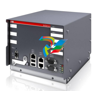
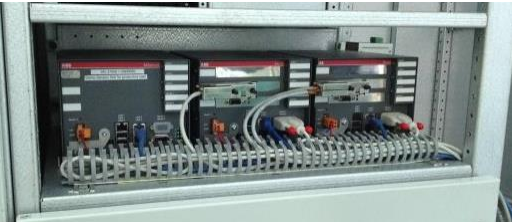
2.3 Hardware characteristics
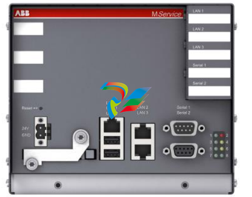
Fig. 2: MService interfaces
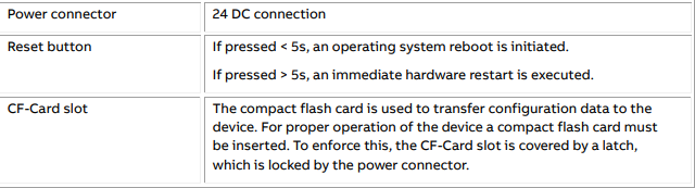
All interfaces of the MService devices are in the front plate. The following interfaces are relevant for the
operation of the device:
3.2 MService mounting in MNS and MNS iS Cubicle
The MService device is placed in the control compartment of a MNS iS switchboard. The device is mechanically held by means of a device support (single support 300mm for MService only, double support
400mm for MLink/MService combinations).
The electrical power (24V DC) is typically taken from the control voltage distribution bar in the same
compartment
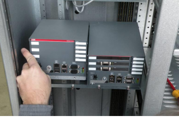
The MService is installed on a MLink mounting kit which is housed in an 8E withdrawable
module compartment of the MNS cubicle. The MLink mounting kit is capable to support
mounting for two MLink and one MService within an 8E compartment. The installation instruction and the required part of the mounting kit can be found in the “1TNA810039 -- Manufacture Instruction – Installation of MService and MLink” .
3.3 MService in MNS and MNS iS network
MService collects the operational data from the switchgear using the built-in OPC Server. Therefore,
the device must be connected to the switchgear network. All MService and MLink devices must be configured appropriately.
Different possibilities exist, how to set up the network, the most common are depicted in the following sections.
Do not connect several MService devices to the same network before the correct network
settings are downloaded and activated. A failure of the network communication may be
result if ignoring this.
Since the design of computer networks is in most cases governed by company rules on site, ABB provides the required network equipment only on special request.
The network sketches in the following sections always assume, that all devices are connected to a network switch forming a local area network (LAN) depicted by the grey line.
3.3.1 Client PC requirements and configuration recommendations
The MService WebHMI uses standard web technologies limiting the software requirements on the client PC to a minimum. To use the web interface of the MService device a standard PC is needed with
the following minimum characteristics
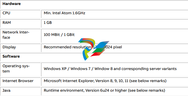
Microsoft Internet Explorer 11
Using version 11 of Internet Explorer requires Java Runtime Environment to be upgraded to at least
Version 7 update 55.
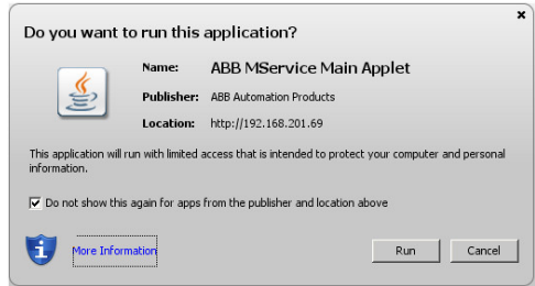
Java Runtime Environment
The main display of the MService WebHMI is implemented as Java applet. Starting with Java 7, Oracle
introduced a security check, asking the user to run the applet. The Java runtime shows a
dialog, asking for permission to run the applet. The Java applet is digitally signed
and the user can select to accept the signature. If the certificate is accepted, the
security dialog is not shown again for this MService and on this PC.
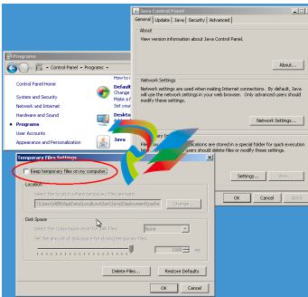
Furthermore, it is recommended to configure the Java Runtime environment in the following manner:
• Disable “Keep temporary files on my computer”
-
 Applied Materials (AMAT) 0190-34512 4-Channel DeviceNet Scanner Interface
 -
 Applied Materials (AMAT) 0190-34282 High-Stability Process Control Module
 -
Applied Materials (AMAT) 0190-27707 High-Precision DeviceNet I/O Controller
-
 Applied Materials (AMAT) 0190-27072 High-Performance Semiconductor Interface
 -
 AMAT 0190-24007 CPCI-3720CF Single Board Computer
 -
 AMAT 0190-23905 Spellman ESC High Voltage Power Supply
 -
 AMAT 0190-22967 High-Density Analog I/O Control Board
 -
 AMAT 0190-22543 High-Precision Analog Input/Output Module
 -
 AMAT 0190-17964 Etch DPS Interlock Module
 -
 AMAT 0190-17894 Interlock Module Conductor HART
 -
 AMAT 0190-17081 2U CompactPCI System Host Processor
 -
 AMAT 0190-16926 and 0190-16928 Based on Compact PCI
 -
AMAT 0190-15915 Intelligent I/O Control Module
-
 AMAT 0190-15840 4-Port UPA DeviceNet Interface Module
 -
 AMAT 0190-15384 Advanced Digital Signal Interface Module
 -
 AMAT 0190-14027 Wafer Flat Finder PCB
 -
 AMAT 0190-12695 SBS CL7 3U CompactPCI Single Board Computer
 -
 AMAT 0190-11817 CP3-SER16-TTL 16-Port Serial Interface Card
 -
 AMAT 0190-11524 CDN500-25 Interlock Module
 -
 AMAT 0190-07450 CompactPCI 48-Channel Digital I/O Interface Board
 -
 AMAT 0190-05990-001 Maglev Rotation System Controller (300mm)
 -
 AMAT 0190-05647 LK3710 Serial Module Transition Card
 -
 AMAT 0190-04457 High-Performance Integrated Circuit Control Module
 -
 Applied Materials (AMAT) 0190-04098 | 5.X Factory Interface I/O Distribution Board
 -
 Applied Materials (AMAT) 0190-03705 | MF Producer SE/E Interlock Module
 -
 Applied Materials (AMAT) 0190-02748 | Flex Scanner Transition Module
 -
 Applied Materials (AMAT) 0190-02362 | Mainframe Interlock 1 Relay Module
 -
 Applied Materials (AMAT) 0190-01227 | Intelligent Motor Control OMS Board
 -
 Applied Materials (AMAT) 0190-00318 | VME 486 Video Controller
 -
 Applied Materials (AMAT) 0130-14007 | Advanced RF Signal Assembly
 -
 Applied Materials (AMAT) 0130-14005 | RF Cable/Interface Assembly
 -
 Applied Materials (AMAT) 0130-01218 | High-Efficiency RF Interface Controller
 -
 Applied Materials (AMAT) 0110-77040 | Head Pneumatic Controller
 -
 Applied Materials (AMAT) 0110-00077 | Precision Control Module
 -
 AMAT 0101-57015 high-performance Next-Generation Deflection Amplifier Board
 -
 AMAT 0100-77040 critical Head Pneumatic Controller Board
 -
 AMAT 0100-76291 Data Buffer / Memory Expansion Interface
 -
 AMAT 0100-76290 Advanced I/O Interface Board
 -
 AMAT 0100-76269 Control Board / Interface Module
 -
 AMAT 0100-71462-01 high-performance Process Controller PCB
 -
 AMAT 0100-71171 Chamber Interlock Control PCB
 -
 AMAT 0100-71154 Semiconductor Circuit Board / Electronic Group Card
 -
 AMAT 0100-70034 PCB Assembly (PCBA) for Endpoint VGA I/O Interconnect.
 -
 AMAT 0100-38032 ESC (Electrostatic Chuck) Controller PCB
 -
 AMAT 0100-36035 DPS Source Match / Seriplex I/O Distribution PCB
 -
 AMAT 0100-35231 Seriplex I/O Distribution Module
 -
 AMAT 0100-35217 TC Amp Interlock PCB Module
 -
 AMAT 0100-35065 High-Precision Serial Isolator PCB
 -
 AMAT 0100-35054 Advanced Chamber Interface Module
 -
 AMAT 0100-20453 DeviceNet Digital I/O Interface Board
 -
 AMAT 0100-20100 High-Performance Semiconductor Component
 -
 AMAT 0100-20068 Precision CCD Image Control Board
 -
 AMAT 0100-20064 Advanced Semiconductor Control Module
 -
Applied Materials (AMAT) 0100-20018 Advanced Communication Interface Module
-
 Applied Materials (AMAT) 0100-20016 High-Performance Interface and Control Module
 -
 Applied Materials (AMAT) 0100-20003 Digital I/O (DI/DO) Interface Board
 -
 Applied Materials (AMAT) 0100-20001 System Electronics Interface (SEI) / PCB Assembly
 -
 Applied Materials (AMAT) 0100-11030 Chamber Hardware / Gas Distribution Component
 -
 Applied Materials (AMAT) 0100-11022 Semiconductor Board Card
 -
 Applied Materials (AMAT) 0100-11018 Advanced Interface Control Module
 -
 Applied Materials (AMAT) 0100-11001 Precision Analog Output Board
 -
 Applied Materials (AMAT) 0100-11000 High-Precision Analog Input Board
 -
 Applied Materials (AMAT) 0100-09237 Advanced Signal Interface Module
 -
 Applied Materials (AMAT) 0100-09204 Advanced Digital Interface Control Board
 -
 Applied Materials (AMAT) 0100-09172 High-Density Digital I/O Control Board
 -
 Applied Materials (AMAT) 0100-09137 High-Performance VME Control Module
 -
 Applied Materials (AMAT) 0100-09054 Precision Analog Input Board
 -
 Applied Materials (AMAT) 0100-09029 Turbo Interconnect Interface Module
 -
 AMAT 0100-03391 Precision Semiconductor Control
 -
 AMAT 0100-01984 | VME System Interface & Logic Controller Board
 -
 AMAT 0100-01363 | VME Intelligent System Control & I/O Board
 -
 AMAT 0100-01321 | VME DeviceNet Scanner / Interface Board
 -
AMAT 0100-00793 | VME Multi-Channel Interface & Logic Board
-
 AMAT 0100-00689 | VME PCB Power Module
 -
 AMAT 0100-00580 | VME Intelligent System Controller Board
 -
 AMAT 0100-00523 | VME Multi-Channel Analog-to-Digital (A/D) Board
 -
 AMAT 0100-00493 | VME Multi-Function System Controller Board
 -
 AMAT 0100-00398 | VME Interface System Control Board
 -
 AMAT 0100-00369 | VME 12-Channel High-Speed Stepper Motor Controller
 -
 AMAT 0100-00196 | VME System Mainframe CPU Controller Board
 -
 AMAT 0100-00169 | VME 12-Channel Stepper Motor Controller Board
 -
 AMAT 0100-00162 | VME Dual Channel Serial Communication Board
 -
 AMAT 0100-00137 | VME Stepper Motor Controller Interface Board
 -
 AMAT 0100-00075 | VME Digital Input/Output (DI/O) Interface Board
 -
 AMAT 0100-00007 VME Analog Input/Output Interface Board
 -
 AMAT 0100-00002 | VME Slave I/O Interface PCB
 -
 AMAT 0090-05596 High-Voltage DC Power Cable Assembly
 -
 AMAT 0090-01809 | High-Performance RF Power Cable Assembly
 -
 AMAT 0010-29958 | CCM HART 3 Mainframe Control Assembly
 -
 AMAT 0010-20003 System Controller Card Cage Assembly
 -
.png) AMAT 0010-11239 PVD High-Voltage Power Interface Assembly
AMAT 0010-11239 PVD High-Voltage Power Interface Assembly -
 AMAT 0010-09416 RF Matching Network Assembly
 -
 AMAT 0010-00019 Analog Power Supply Assembly
 -
 AMAT AS00009-02 (31-000-00940) | Precision Semiconductor Component
 -
 AMAT 0010-00028 Power Supply Module
 -
 AMAT 0330-1586A Serial Communication PCB
 -
 AMAT 0190-09690 Seriplex SENSORbus SPX-MUXADIO-001
 -
 AMAT 0190-04397 DeviceNet I/O Interface Board
 -
 AMAT 0190-02506 DeviceNet I/O Interface Card
 -
 AMAT 0090-00475 Seriplex 210 MUXADIO
 -
 AMAT 410-0198-1 Multi-Output Switching Power Supply
 -
 AMAT 0100-20458 high-reliability Configurable Interlock Personality Board
 -
 AMAT VAS104350-0415 Gasline Heater Control Unit
 -
 AMAT VME6U1V2 VMEbus Backplane Interface Module
 -
AMAT 0920-01070 high-performance RF Power Generator
-
 AMAT 0090-76133A VME Single Board Computer (SBC)
 -
 AMAT 0190-24115 DeviceNet I/O Interface Card
 -
 AMAT 0190-37607 Backplane / Base Board Assembly
 -
 AMAT 0190-32372 Analog Input/Output (I/O) Board
 -
 AMAT 0190-09956 Loadlock Interface PCB Base Assembly
 -
 AMAT 0190-07908 four-channel DeviceNet Interface Card
 -
 AMAT 0190-07905 (UPS) control board
 -
 AMAT 0190-07502 Precision Controller / Interface Board
 -
 AMAT 0190-03680 I/O Backplane
 -
 AMAT 0190-02200 Water Leak Detection Control Board
 -
 AMAT 0100-76124 Digital I/O Board Assembly
 -
 AMAT 0100-35563 Leak Detector Configuration PCB
 -
 AMAT 0100-35250 Chamber Interface DPS Centura PCB
 -
 AMAT 0100-35124 Seriplex I/O Distribution Board
 -
 AMAT 0100-35058 Loadlock Interlocks PCB
 -
 AMAT 0100-20213 RF Match Detector PCB
 -
 AMAT 0100-20063 Interface PCB Assembly
 -
 AMAT 0100-09225 TC AMP/INTERLOCK PCB
 -
 AMAT 0100-09153 Gas Panel Interface PCB
 -
 AMAT 0100-09127 Loader Interconnect Board
 -
 AMAT 0100-09009 Buffer I/O PCB Card
 -
 AMAT 0100-02813 Signal Conditioning Board
 -
 AMAT 0100-01911 AC Gas Heater Control Board


