
Summary of the User Manual for ABB InstrumentationIT 2600T Pressure Transmitter
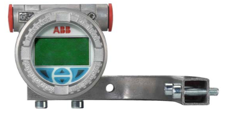
Summary of ABB 364Gx/Ax Pressure Transmitter User Manual
This document is the user manual for the 364Gx and 364Ax models of ABB InstrumentationIT 2600T series pressure transmitters, covering operational guidelines throughout the entire lifecycle of the device, including safety specifications, installation, configuration, operation, calibration, maintenance, and troubleshooting.
I. Safety and Responsibility
Personnel Qualification Requirements
Only trained professional personnel are allowed to perform installation, wiring, commissioning, and maintenance. They must have qualifications in electrical operations, high-pressure handling, and corrosive medium management, and use insulated tools compliant with DIN EN 60900 standards.Core Safety Warnings
The device may come into contact with high pressure or corrosive media. Before operation, pressure must be relieved and medium compatibility checked.
Electrical installation must comply with local regulations (such as DIN 31000/VDE 1000). In explosive environments, non-sparking tools must be used.
Misuse is prohibited (e.g., using as a climbing aid, supporting loads, tampering with nameplates or housings). Unauthorized repairs or modifications will invalidate the warranty.
Environmental Protection and Disposal
Unpacking and Inspection
After unpacking, check for transportation damage and accessories (including manuals, calibration reports, 3mm Allen key, etc.). Storage must use the original packaging, and the environment must meet technical parameter requirements (no storage time limit, but warranty terms apply).Installation Preparation
Confirm that the device model meets measurement requirements (range, temperature resistance, explosion-proof rating, etc.) and check the compatibility of components in contact with the medium (gaskets, process interfaces). Installation should avoid interfering environments such as severe temperature changes and vibrations.Installation Methods
Pipe Mounting: Supports 2-inch pipes. The bracket fixing torque is 10-12Nm, and the transmitter fixing torque is 1±0.2Nm.
Wall Mounting: The bracket fixing torque is 10-12Nm, and the transmitter fixing torque is 1±0.2Nm; gaskets must be used.
LCD Display Positioning: The display direction can be adjusted by rotating through 4 90° interfaces on the back.
Wiring Requirements
Use 18-22 AWG (0.35-0.8mm²) twisted-pair cables with a maximum length of 1500 meters. The shield layer must be grounded at only one end.
Protective earthing must be connected to a dedicated terminal with a grounding resistance ≤5Ω, and the wire specification must be ≥15 AWG (1.6mm²).
HART communication requires a loop resistance ≥250Ω; additional resistance must be added if insufficient.
Calibration Preparation
A stable pressure source and reference indicator (with accuracy at least 4 times that of the transmitter) are required. Ensure the device is powered off, free of residual media, and the write protection switch is set to "OFF".Sensor Adjustment
Zero Adjustment: Perform via CoMeter, HHT, or PC under stable zero pressure.
High/Low Point Adjustment: Calibrate at low and high range pressures via LCD (Calibrate > Sensor Trim), HHT, or PC.
Output Adjustment
4mA and 20mA outputs can be calibrated via LCD (Calibrate > Output Trim) to ensure consistency with standard ammeters.PV Scaling and Reset
PV scaling is used to align the process zero, supporting pressure-based automatic setting or manual input of offset values. Sensor adjustment functions are disabled after scaling.
PV scaling can be removed via LCD (Device Config > PV Scaling > Reset PV Scaling).
Factory calibration reset: Restore factory calibration values of sensors and outputs via LCD (Calibrate > Reset to Factory Trim).
Common Faults and Solutions
No Output Current: Check power supply (10.5-42Vdc), polarity, wiring cleanliness; replace the electronic module if necessary.
Abnormal Output: Check if pressure is within range, if output is saturated, and if damping settings are reasonable; perform output calibration if needed.
HART Communication Failure: Confirm loop resistance ≥250Ω, correct address, and noise-free power supply.
Diagnostic Information
The LCD displays common fault codes such as "Electronic Fail" (electronic fault), "Sensor Fail" (sensor fault), and "PV out of Limit" (PV overrange). These can be resolved by restarting, checking process conditions, or replacing components.Global Service Support
Contact information for service centers in regions such as Italy, Germany, the United States, Canada, India, and China is provided, supporting technical consultation and maintenance.Certifications and Compliance
Complies with explosion-proof standards such as ATEX, FM, and CSA, with IP67 protection rating, and meets PED directive requirements (based on Sound Engineering Practice, SEP).
The device materials are recyclable. It is not subject to the WEEE Directive 2002/96/EC and must be disposed of through professional recycling agencies; mixing with municipal waste is prohibited.
II. Installation and Storage
IV. Calibration and Maintenance
V. Troubleshooting and Diagnostics
VI. Other Information
-
 AEROTECH SM Series High-Performance Stepper Motors
 -
 AEROTECH BLMSC Series Linear Motors
 -
 AEROTECH Custom Linear Motors
 -
 AEROTECH BMS Series Brushless, Slotless Rotary Motors
 -
 AEROTECH BM Series Brushless Rotary Motors
 -
 AEROTECH BLMX Series Linear Motors
 -
 AEROTECH BLMH Series Linear Motors
 -
 AEROTECH BLM Series Linear Motors
 -
 AEROTECH BLMC Series Linear Motors
 -
 AEROTECH BLMUC-143 Linear motor forcer with thermistor
 -
AEROTECH BLMUC-111 Linear motor forcer with thermistor
-
AEROTECH BLMUC-95 Linear motor forcer with thermistor
-
AEROTECH BLMUC-79 Linear motor forcer with thermistor
-
AEROTECH BLMUC Series Linear Motors
-
 AEROTECH Automation1 FLEX Distributed Amplifier Multi-Axis Servo Control System
 -
 AEROTECH Automation1 HXA4 6-Axis Hexapod Servo Drive
 -
 AEROTECH Automation1 iHXA4 6-Axis Hexapod Servo Drive with Motion Controller
 -
 AEROTECH Modular System Control Console
 -
 AEROTECH TV Series Transformers
 -
 AEROTECH TM Series Transformers
 -
 AEROTECH UFM Noise Filter Module
 -
 AEROTECH MFM Motor Filter Module
 -
 AEROTECH MPG Handwheel Pendant
 -
 AEROTECH Automation1 Multi-Axis Joystick
 -
 AEROTECH ETM Enhanced Throughput Module
 -
 AEROTECH Automation1 XL4s High-Speed, Single-Phase Linear Servo Drive
 -
 AEROTECH Automation1 XL2e Enhanced, Compact Linear Servo Drive
 -
 Automation1 iXL2e Enhanced, Compact Linear Servo Drive with Motion Controller
 -
 AEROTECH Automation1 XL5e Enhanced, Linear Servo Drive
 -
 AEROTECH Automation1 iXL5e Enhanced Linear Servo Drive with Motion Controller
 -
 AEROTECH Automation1 GI4 Laser Scan Head Controller
 -
 AEROTECH Automation1 SI4 Stepper Interface
 -
AEROTECH Automation1 XI4 Servo Interface
-
 AEROTECH AEROTECH Automation1 iXI4 Servo Interface with Motion Controller
 -
 AEROTECH Automation1 XC6e Enhanced, High-Power PWM Servo Drive
 -
 AEROTECH Automation1 iXC6e Enhanced, High-Power PWM Servo Drive with Motion Controller
 -
 AEROTECH Automation1 XC2 Compact PWM Servo Drive
 -
 AEROTECH Automation1 XC4 PWM Servo Drive
 -
 AEROTECH Automation1 GL4 Galvo Laser Scan Head Linear Drive
 -
 AEROTECH Automation1 XC2e Enhanced, Compact Servo Drive with PWM+
 -
 AEROTECH Automation1 XC4e Enhanced, PWM Servo Drive
 -
 AEROTECH Automation1 XR3 Multi-Axis Servo Drive Rack
 -
 AEROTECH Automation1 iXR3 Multi-Axis Servo Drive Rack with Motion Controller
 -
 AEROTECH Automation1 iXC2 Compact PWM Servo Drive with Motion Controller
 -
 AEROTECH Automation1 iXC2e Enhanced, Compact PWM+ Servo Drive with Motion Controller
 -
 AEROTECH Automation1 iXC4 PWM Servo Drive with Motion Controller
 -
 AEROTECH Automation1 iXC4e Enhanced, PWM Servo Drive with Motion Controller
 -
 AEROTECH Automation1 iPC Industrial PC with Motion Controller
 -
 AEROTECH EPICS & TANGO Drivers for Distributed Control Systems
 -
 AEROTECH .NET, C, Python & LabVIEW APIs Custom Application Develotpmen
 -
 AEROTECH Automation1 Industrial Ethernet Support
 -
 AEROTECH Automation1 iSMC Intelligent, Software-Based Motion Controller
 -
 AEROTECH Automation1 iXA4 1- 2- or 4-Axis PWM Servo Drive with Motion Controller
 -
 AEROTECH Automation1 XA4 1- 2- or 4-Axis PWM Servo Drive
 -
 CTI 2500-ADP2-DISC Discrete Wiring Adapter for Series 500
 -
 CTI 2500-ADP1 Analog Wiring Adapter for Series 500
 -
 CTI 2500C-RADP-RS485 Remote Base Controller Adapter for Series 500
 -
 CTI 2500C-RADP-RBC Profibus RBC Adapter for Series 500
 -
 CTI 2500C-PADP-120V 120VAC 50W Power Supply for Series 500
 -
 CTI 2500-RADP RBC Adapter for Series 500
 -
 CTI 2500-R4500 520/530/DBC Adapter for Series 500 - MATURE
 -
 CTI 2500-PADP Power Supply Adapter for Series 500
 -
 CTI 2500-IADP I/O Adapter for Series 500
 -
 CTI 2500-VP15A-N4-W7 15" Flat-Panel PC with Windows® 7 Embedded
 -
 CTI 2500S-27-1750 Slice I/O, Ethernet, RS232/485. 900MHz, 2DIO / 4UAI / 2AI
 -
 CTI 2500S-26-1750 Slice I/O, Ethernet, RS232/485. 900MHz, 8DIO / 2UAI
 -
 CTI 2500S-23-1750 Slice I/O, Ethernet, RS232/485. 900MHz, 4DI / 4DO / 2UAI / 2AO
 -
 CTI 2500S-27-1550 Slice I/O, RS232/485. 2DIO / 4UAI / 2AI
 -
 CTI 2500S-26-1550 Slice I/O, RS232/485. 8DIO / 2UAI
 -
 CTI 2500S-23-1550 Slice I/O, RS232/485. 4DI / 4DO / 2UAI / 2AO
 -
 CTI 2500S-27-1050 Slice I/O, Ethernet, 2DIO / 4UAI / 2AI
 -
 CTI 2500S-26-1050 Slice I/O, Ethernet, 8DIO / 2UAI
 -
 CTI 2500S-23-1050 Slice I/O, Ethernet, 4DI / 4DO / 2UAI / 2AO
 -
 CTI 2500C-32F-CJC 32-Pin Field Wiring Connector with Cold Junction Compensation
 -
 CTI 2500C-32F 32-Pin Field Wiring Connector
 -
 CTI 2500C-8-TC Eight Thermocouple Inputs
 -
 CTI 2500C-8-RTD Eight RTD Inputs
 -
 CTI 2500C-8-RL-FC 8 Form-C Relay Outputs
 -
 CTI 2500C-8-IDO-24V 8 Isolated 24VDC Outputs
 -
 CTI 2500C-8-IDO-120V 8 Isolated 120VAC Outputs
 -
 CTI 2500C-16-DO-24V Sixteen 24VDC Digital Outputs
 -
 CTI 2500C-16-DO-120V Sixteen 120VAC Digital Outputs
 -
.png) CTI 500C-16-IDI-24V Sixteen Isolated 24V AC/DC Digital Inputs
CTI 500C-16-IDI-24V Sixteen Isolated 24V AC/DC Digital Inputs -
 CTI 2500C-16-IDI-120V Sixteen Isolated 120V AC/DC Digital Inputs
 -
 CTI 2500C-16-DIDO-SIM Sixteen Digital Input and Output SImulator
 -
 CTI 2500C-16-DI-24V Sixteen 24V AC/DC Digital Inputs
 -
 CTI 2500C-16-DI-120V Sixteen 120V AC/DC Digital Inputs
 -
 CTI 2500C-RBC-RS485 RS485 Remote Base Controller
 -
 CTI 2500C-RBC-PRF Profibus Remote Base Controller
 -
 CTI 2500C-PS-24V-35 35-Watt DC Power Supply
 -
 CTI 2500C-PS-120V-35 35-Watt AC Power Supply
 -
 CTI 2500C-R8 Eight-Slot Base
 -
 CTI 2500C-R4 Four-Slot Base
 -
 CTI 2500C-R16 Sixteen-Slot Base
 -
 CTI 2500C-2572-B Fast Ethernet TCP/IP Adapter
 -
 CTI 2500C-J750 Compact Janus PAC with 3MB Project Memory
 -
 CTI 2500C-C300 CPU with 512K User Memory
 -
 CTI 2500C-C200 CPU with 256K User Memory
 -
 CTI 2500C-C100 CPU with 128K User Memory
 -
 CTI 2500C-8-AO 8 Analog Outputs
 -
 CTI 2500C-8-AI 8 Analog Inputs
 -
 CTI 2559-FCAL Precision Calibration Connector
 -
 CTI 2559-FPC 40-Position Screw-Terminal Connector
 -
 CTI 2500-RFC PLC to RF Modem Cable
 -
 CTI 2500-40F 40-Position Standard Screw-Terminal Connector
 -
 CTI 2505 Vibration Sensor Interface Module
 -
 CTI 2554-A 4-Channel Isolated High Speed Counter Module
 -
 CTI 2553-A 2-Channel Mag Meter Input Module
 -
 CTI 2502 2-Channel High Speed Counter Input Module
 -
 CTI 2559-TC 8-Channel Thermocouple Input Module
 -
 CTI 2556-A 16-Channel Isolated Thermocouple Input Module
 -
 CTI 2556 16-Channel Isolated Thermocouple Input Module
 -
 CTI 2551-A 8-Channel Isolated Thermocouple Input Module
 -
 CTI 2559-RTD 8-Channel RTD Input Module
 -
 CTI 2557-A 16-Channel RTD Input Module
 -
 CTI 2557 16-Channel RTD Input Module
 -
 CTI 2552-A 8-Channel Isolated RTD Input Module
 -
 CTI 2534 8-Point Form-C Relay Output Module
 -
 CTI 2532 16-Point Form-A Relay Output Module
 -
 CTI 2531 32-Point Form-A Relay Output Module
 -
 CTI 2530 8-Point Form-C Relay Output Module
 -
 CTI 2562 8-Channel Analog Output Module
 -
 CTI 2560-A 8-Channel Isolated Analog Output Module
 -
 CTI 2501 8in/4out Analog Module
 -
 CTI 2558 8-Channel Analog Input Module
 -
 CTI 2555-A 16-Channel Analog Input Module
 -
 CTI 2550-A 8-Channel Isolated Analog Input Module
 -
 CTI 2599 8/16/32-Point AC Output Module


