
SAM Lyngsø MarineDMS2100i Bridge Manoeuvring System MAN B&W ME/ME-C Engines User Manual
Diesel Manoeuvring System, DMS2100i Page 6 of 112
User Manual for MAN B&W ME/ME-C Engines 2004.11.02
1. DMS2100i Introduction
The Diesel Manoeuvring System - DMS2100i is a Bridge Manoeuvring System used for remote
control of a ship’s Propulsion Line, with a MAN B&W two-stroke low speed ME-Engine connected to a Fixed Pitch Propeller (FPP).
The DMS2100i is operated by means of Telegraph Levers and standard DMS2100i Panels with
build in four-line display.
The DMS2100i is operated as a completely independent stand-alone system, with all information and internal alarms displayed on the DMS Operator Panels.
When the DMS2100i are delivered together with a Lyngsø Marine Universal Monitoring System, UMS2100 alarm system or as an integrated part of the Universal Control System
UCS2100, the systems can be interconnected by means of a communication network, so that
alarms, indications and measurements values from the DMS2100i can be displayed on the
Graphical Operator Station (GOS) and alarm Panels in the Alarm and Control System also.
The DMS2100i can be configured to provide complete control for:
· Main Engine Remote Start/Stop from Bridge
· Start Blocking indications
· Main Engine Setpoint System
· Main Engine Shutdown Indications from ME Safety System
· Main Engine Slowdown System
· Main Engine Speed Measurement and Indication
· Control Transfer for Bridge/ECR/Local Change-over
· Sub-telegraph Control with Finished With Engine (FWE), Stand-by and Sea-mode
· Main Engine Running Mode Selector (Economy mode, Emission Mode etc.)
· Dual Serial Interface to the ME-Engine Electronic Control System (ECS)
· Alarm Announcement and Indication
The DMS2100i can be extended with the following options:
· DPS2100 Engine Safety System (independent system for Shutdowns and overspeed)
· Communication Telegraph System for Bridge order communication to ECR/Local
· Bridge Wing Control (Wing Panels Optional) and Electric Shaft on Telegraph Levers
· Manoeuvring Order Printer integrated in the system
· Integration with Lyngsø Marine Alarm and Control System
· Serial interface (Modbus) to other types of ships alarm system
This User Manual gives an overview of the hardware and describes the functionality of the
DMS2100i Bridge Manoeuvring System, and includes wiring diagrams etc.
Also the Monitoring and Control System, the Safety System, the Telegraph Lever System with
Electric Shaft for the Bridge Wings and other related system and options are described to give a
complete overview of the remote control system.
1.1 References
[1] MBD ME-Engine Interface & Requirements to External Control Systems
[2] MBD ME-Engine Engine Control System – I/O Specification
[2] MBD ME-Engine Engine Control System – Available Options
[2] MBD ME-Engine Serial Interface – Requirement Specification
[2] Propulsion Control System, PCS2100, System Description
[3] Diesel Protection System, DPS2100, System Description and User Manual
[4] Universal Monitoring System, UMS2100, System Description and User Manual
[5] Universal Control System, UCS2100, System Description and User Manual
1.2 Definitions and Abbreviations
AAM Analog Output Module type 401
AEM Analog Input Module type 402
AI Analog Input
AO Analog Output
BAP Basic Alarm Panel
BRG Bridge
BT Bow Thruster
CPP Controllable Pitch Propeller
DG Diesel Generator
DI Digital Input
DO Digital Output
DMS Diesel Manoeuvring System - Bridge Manoeuvring System
DNM Dual STELLA NET communication interface Module
DPS Diesel Protection System - Engine Safety System
DSN Dual STELLA NET communication interface
DZM DrehZahl relais Module - speed relay module type 402
ECR Engine Control Room
ECS Electronic Control System for MBD ME-Engine
EMG Emergency
ENT Enter key
ER Engine Room
ESC Escape key
ESS Engine Safety System
EXH Exhaust
FIM 405 Filter Module for 24 Vdc Power Supply
FPP Fixed Pitch Propeller
GOS Graphic Operator Station
I/O Input/Output
I/P Current to Pressure converter
IOM Input Output Module - type 402
LC Local Control
LCD Liquid Crystal Display
LED Light Emitting Diode
LOP Local Operator Panel
LP Low pass Filter
LM Lyngsø Marine
MAM MIC40 Input/Output Adapter, Gamma to digital I/O modules
Diesel Manoeuvring System, DMS2100i Page 9 of 112
User Manual for MAN B&W ME/ME-C Engines 2004.11.02
810.000.705-01 Lyngsø Marine A/S
SAM Electronics GmbH
MBD MAN B&W Diesel
ME Main Engine
MEP Mean Effective Cylinder Pressure
MIC40 Input/Output Adapter, Gamma to digital I/O modules
MSB Main Switch Board
MXM Multiplexer Module type 402 (16 channel analog input)
NA Not Applicable
PCC Propulsion Control Cabinet
PCS Propulsion Control System
PLC Programmable Logic Controller - Gamma computer
PMS Power Management System - ships generator control system
PS Port Side
PTO Power Take Off
REM Binary input and relay output module type 401
RPM Rotations Per Minute
SB Star Board side
SG Shaft Generator
SHD Shutdown
SIM Serial Input/Output Interface Module
SIO Serial Input/Output Communication
SLD Slowdown
ST Stern Thruster
TAM Tacho Adapter Module type 401
TC Turbo Charger
UPS Uninterruptible Power Supply
UMS Universal Monitoring System - ships alarm system
UCS Universal Control System- ships alarm and control system
Diesel Manoeuvring System, DMS2100i Page 10 of 112
User Manual for MAN B&W ME/ME-C Engines 2004.11.02
810.000.705-01 Lyngsø Marine A/S
SAM Electronics GmbH
2. DMS2100i System Overview
The DMS2100i control functions for a Propulsion Line existing of a MAN B&W two-stroke
low speed ME-Engine with Fixed Pitch Propeller are handled by one DMS2100i Gamma PLC
mounted in the DMS control cabinet, together with the units for a DPS2100 Engine Safety System.
The Main Engine Safety System is completely independent of the DMS. The Main Engine may
be equipped with a standard Safety System from the Main Engine manufacturer. If the Main Engine manufacturer supply does not include a Safety System, the DMS can be delivered together
with an independent Diesel Protection System, DPS2100 Safety System.
Other Gamma PLC's in the UMS/UCS2100 Alarm and Control System handles the alarm and
monitoring part of the machinery components controlled by the DMS2100i.
In case that alarms from the Main Engine are connected to the DMS Gamma, it must be alarms
relevant for the Main Engine controlled by that particular DMS Gamma only, because they will
be displayed as DMS alarms on the DMS Panels, such as e.g. alarms initiating a Slowdown/load reduction, startblockings etc.
The DMS2100i and the UCS2100 Alarm and Control system are independent systems, each
with its own Gamma PLC’s, only connected by a network to transfer alarms and information to
the GOS and printers (Manoeuvring Order Printer). The network will also be used for automatic operation of the Power Management System (PMS) e.g. in case of mode change to/from a
mode where the SG is connected to a Bow Thruster (BT) and/or Stern Thruster (ST).
Slowdowns for the Main Engine and optional RPM up/down signals from the Power Management System (for frequency control, load sharing and synchronising purposes) are transferred as
hardwired signal lines for safety reasons. The Slowdown inputs to the DMS2100i are defined
as supervised inputs, i.e. cable break can be detected.
All hardware component and logic circuitry of the DMS2100i and the UCS2100 Alarm and
Control System is independent. That means it will still be possible to control the propulsion
machinery even in case of a total breakdown of the Alarm and Monitoring System.
The power supply for the DMS2100i as well as the DPS2100 and UCS2100 must be Uninterruptible Power Supply (UPS) protected. There must be a separate fuse for the DMS2100i
Gamma, the DPS PLC and the remaining hardware connected to this system.
The following part of the remote control system are described in this section:
· DMS2100i Main Cabinet (Gamma PLC, I/O Modules etc.)
· DMS Panels for remote control of the propulsion machinery
· ECR Components for Manual ECR Control of the propulsion machinery
· Local Operator Panel for Local Control of the propulsion machinery
· DPS2100 Engine Safety System
· Telegraph Lever System
· Electric Shaft for Bridge Wings control
· Communication Telegraph System
· Main Engine Speed Measurement
Diesel Manoeuvring System, DMS2100i Page 11 of 112
User Manual for MAN B&W ME/ME-C Engines 2004.11.02
810.000.705-01 Lyngsø Marine A/S
SAM Electronics GmbH
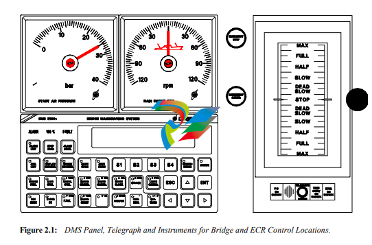
2.1 DMS Panels for Remote Control
For operation of a ship’s Propulsion Line, the DMS is connected with DMS operator panels on
all control locations, including instruments for RPM and Start air pressure indication and a
pushbutton for Emergency stop:
· one in the Engine Control Room (ECR)
· one on the Bridge
· two panels on the Bridge starboard and Port Wings (optional)
· a fifth panel can be mounted on an Aft Bridge (optional)
The DMS Panel is mounted together with a Setpoint Lever on all Control Locations with DMS
Control, i.e. normally Bridge and ECR, and optionally on the Bridge Wings.
Diesel Manoeuvring System, DMS2100i Page 12 of 112
User Manual for MAN B&W ME/ME-C Engines 2004.11.02
810.000.705-01 Lyngsø Marine A/S
SAM Electronics GmbH
2.1.1 DMS Panel Functions
The following main functions are available on each control location for the Main Engine/Propulsion Line:
Analog instruments for indication of ME RPM
Analog instruments for indication of ME Start Air pressure
Dimmer potentiometer for illumination of the analog instruments (Bridge only)
Emergency stop push-button with cover
DMS2100i Operator Panel with the following functions:
ME: <Runstat> 100.0 RPM, StAir 30.00
BAR
LIMITER:<Indic1>
TLG BC: ±120.0 ECR: ±120.0 EGS: 20.0
RPM
<Oldest unacknowledged alarm/Alarm
stat>
Four lines display with 40 characters on each line
Softkeys [ S1 ] - [ S4 ] for operation of DMS functions
Six selection keys: [ ESC ], [ ENT ]
and four [ Arrow ] keys
[ Select ] of DMS control functions of
[ Status ], [ Control ] and [ Settings ]
Diesel Manoeuvring System, DMS2100i Page 13 of 112
User Manual for MAN B&W ME/ME-C Engines 2004.11.02
810.000.705-01 Lyngsø Marine A/S
SAM Electronics GmbH
Control location selection and indication for:
[ Bridge Ctrl. ] key for indication and Request / Acknowledge of Automatic
Bridge.
References: Chapter 3.1.
[ E.C.R. Control ] key for indication and Request / Acknowledge of ECR
Control Station (Automatic ECR or Manual ECR Control).
References: Chapter 3.1.
[ Local Ctrl. ] key for indication and Request / Acknowledge of Local (Emergency) Control Station. (Manual LOP Control)
References: Chapter 3.1.
SUB-Telegraph selection and indication for:
[ Sea Mode ] operation and indication key:
Activation of this key commands Sea Mode and alarm for this is released.
Mode conditions: Control air on, Safety air on, Main start valve not blocked,
Starting air distributor not blocked and Turning gear not engaged.
When unacknowledged or conditions not fulfilled, the green LED is flashing.
When Sea Mode is present, the green LED is ON.
References: Chapter 3.2.3
[ Stand By ] operation and indication key:
Activation of this key commands Stand By at the Main Engine and alarm for
this is released.
Mode conditions: Control air on, Safety air on, Main start valve not blocked,
Starting air distributor not blocked and Turning gear not engaged.
When unacknowledged or conditions not fulfilled, the green LED is flashing.
When Stand By is present, the green LED is ON.
References: Chapter 3.2.2
[ F.W.E. ] operation and indication key:
Activation of this key commands Finished With Engine and alarm for this is
released.
Mode conditions: Control air pressure off, Safety air pressure off
and Main start valve blocked.
When unacknowledged or conditions not fulfilled, the green LED is flashing.
When Finished With Engine is present, the green LED is ON.
References: Chapter 3.2.1
Diesel Manoeuvring System, DMS2100i Page 14 of 112
User Manual for MAN B&W ME/ME-C Engines 2004.11.02
810.000.705-01 Lyngsø Marine A/S
SAM Electronics GmbH
Slowdown operation and indication for:
[ Slow Down ] operation and indication key:
Activation of the key invokes the Slowdown status list at the LCD display.
When Slowdown is active, the red LED is ON.
References: Chapter 3.5.
[ Slowd. Cancel ] operation and indication key:
Slowdown may be cancelled, when in Automatic Bridge or Automatic ECR
control
When in Manual ECR Control, operation takes place from the DMS as well.
When Slowdown prewarning is present, the red LED is flashing.
When the Slowdown situation is cancelled, the red LED is ON.
References: Chapter 3.5.
[ Slowd. Reset ] operation and indication key:
Slowdown may be reset, when in Automatic Bridge or Automatic ECR control and the slowdown condition is neither present nor cancelled.
When in Manual ECR Control, operation takes place from the DMS as well.
When Slowdown may be reset due to Slowdown condition back to normal or
cancelled the red LED is flashing.
References: Chapter 3.5.
Shutdown operation and indication for:
[ Shut Down ] operation and indication key:
Activation of the key invokes the Shutdown status list at the LCD display.
When Shutdown is active, the red LED is ON.
References: Chapter 3.4 and DPS2100 User Manual
[ Shutd. Cancel ] operation and indication key:
Shutdown may be cancelled, when in Automatic Bridge or Automatic ECR
control.
When not in Automatic DMS Control, operation takes place from the
DPS2100 Operator Panel in ECR, or from the LOP.
When Shutdown prewarning is present, the red LED is flashing.
When the Shutdown situation is cancelled, the red LED is ON.
References: Chapter 3.4 and DPS2100 User Manual
The [ RESET ] and [ CANCEL ] keys for Shutdown and Slow Down keys are only working on
the DMS Operator Panels which are in control, i.e. on anyone of the Bridge Operator Panels in
Bridge Control and on the ECR Operator Panel in Automatic ECR Control, however the Slowdown Reset can be configured to always require reset from the E.C.R. Operator Pane
Diesel Manoeuvring System, DMS2100i Page 15 of 112
User Manual for MAN B&W ME/ME-C Engines 2004.11.02
810.000.705-01 Lyngsø Marine A/S
SAM Electronics GmbH
Startblock and Limits Cancel operation and indication for:
[ Start Block ] operation and indication key:
Activation of the key invokes the Startblocking status list at the LCD display.
When Startblocking is present, the red LED is ON.
[ Limits Cancel ] operation and indication key:
Activation of this key Cancels the RPM Max Limit and Load program of the
DMS2100i as well as raising the Index Limiters in the ME-Engine ECS
System.
When Cancellation is present, the red LED is ON.
The [ Limits Cancel ] key is only working on the DMS Operator Panels,
which are in control, i.e. on anyone of the Bridge Operator Panels in Bridge
Control and on the ECR Operator Panel in Automatic ECR Control.
DMS2100i keys for alarm functions:
[ Stop Horn ] operation key:
Activation of this key stops the buzzer in the DMS Operator Panel.
[ Alarm Acknowledge ] operation key:
Activation of this key acknowledges the alarms present at the LCD display of
the DMS Operator Panel.
The [ Stop Horn ] and [ Alarm Ackn. ] keys can be configured to work on several different
conditions:
1. Both keys are always working in the ECR, e.g. when the Chief Engineer always wants to
be able to acknowledge alarms. Buzzer and [ Stop Horn ] are working on anyone of the
Bridge Operator Panels for all alarms announced on the bridge (configurable), but
[ Alarm Ackn. ] will not be possible on the Bridge.
2. Both keys are working on the present DMS Control Location, i.e. working on anyone of
the Bridge Operator Panels in Bridge Control and on the ECR Operator Panel in ECR
Control.
In connection with an integrated UMS alarm system, where the Watch Station can be changed to
the Bridge, the function of both keys is following the UMS Watch Station.
Diesel Manoeuvring System, DMS2100i Page 16 of 112
User Manual for MAN B&W ME/ME-C Engines 2004.11.02
810.000.705-01 Lyngsø Marine A/S
SAM Electronics GmbH
[ Alarm List ] operation and indication key:
References: Chapter 5.3.
[ Additional List ] operation and indication key:
References: Chapter 5.4.
[Display Channel ] operation and indication key:
References: Chapter 5.5.
[ Adjust Channel ] operation and indication key:
References: Chapter 5.6.
[ Maintenance ] operation and indication key:
References: Chapter 5.7.
[ Dimmer ] operation and indication key:
References: Chapter 5.8.
[ Alarm ] indication lamp for DMS2100i Alarm detected.
Any DMS2100i alarm in chapter 6 activates this indication.
[ Fault ] indication lamp for DMS2100i Operator Panel in Faulty condition,
e.g. missing communication to the Gamma Micro CPU or missing EPROM
inside the panel.
Please refer to chapter 5 and the UMS2100 System Description for further information about the
alarm system functions.
Diesel Manoeuvring System, DMS2100i Page 17 of 112
User Manual for MAN B&W ME/ME-C Engines 2004.11.02
810.000.705-01 Lyngsø Marine A/S
SAM Electronics GmbH
2.2 Manual ECR Control Equipment
All indications and operations, such as Aux. Blowers control and indication of Main Start
Valve position etc. in the ECR Control Console which used to take place on the ECR Sub Panel
are now included in the MBD supplied Main Operator Panel (MOP), please refer to the MBD
instruction manual.
Beside that the following facilities are available:
1. EMERGENCY STOP, i.e. when Emergency Stop is ordered from this pushbutton, then the
red lamp indication is ON. The pushbutton is protected with a plastic cover against unwanted operation. The pushbutton is connected to the Safety System.
2. TAKE CONTROL, i.e. when this pushbutton is activated, the ME-Engine ECS Control System makes a forced Control Transfer to Manual ECR Control. This button overrides all
other Control Transfer functions except the similar Take Control pushbutton on the LOP.
The pushbutton is connected directly to the ME-Engine ECS System.
3. INCREASE LIMITS, i.e. i.e. when this pushbutton is activated in Manual ECR Control, the
ME-Engine ECS will raise the limiters in the Governor System. The pushbutton is connected directly to the ME-Engine ECS System.
4. For Manual ECR Control the ECR Telegraph supplied with the Bridge Manoeuvring System
is equipped with:
· Two 4 – 20mA set points connected directly to the ME-Engine ECS System
· Two Stop Switches connected directly to the ME-Engine ECS System
Diesel Manoeuvring System, DMS2100i Page 18 of 112
User Manual for MAN B&W ME/ME-C Engines 2004.11.02
810.000.705-01 Lyngsø Marine A/S
SAM Electronics GmbH
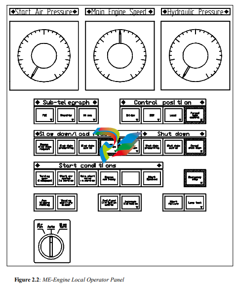
2.3 Local Operator Panel Functions
The ME-Engine Local Operator Panel (LOP), mounted locally at the ME-Engine is used for
fully electronic control from the Emergency Control Stand.
Diesel Manoeuvring System, DMS2100i Page 19 of 112
User Manual for MAN B&W ME/ME-C Engines 2004.11.02
810.000.705-01 Lyngsø Marine A/S
SAM Electronics GmbH
The ME-Engine start/stop and setpoint signals are operated from the Emergency Telegraph receiver mounted close to the LOP, with signals similar to the ECR Telegraph receiver:
· Two 4 – 20mA set points connected directly to the ME-Engine ECS System
· Two Stop Switches connected directly to the ME-Engine ECS System
The DMS2100i do however control the Sub-telegraph, the normal Control Transfer and the
Slowdown indications, and the DPS2100 Safety System control the Shutdown indications, but
the ECS will still be able to control the ME-Engine, even in case of the DMS not functioning.
The following main functions are available on the ME-Engine Local Operator Panel:
· Analog instruments for indication of: Hydraulic Pressure
· Analog instruments for indication of: ME RPM
· Analog instruments for indication of: Starting Air Pressure
· DMS Subtelegraph [Finished With Engine], [Standby] and [At Sea] selection and indication
· DMS Control transfer [Bridge], [ECR] and [Local] control selection and indication
· [Forced take Control] selection and indication
· [Manual Slowdown Request] indication
· DMS [Slow Prewarning] and [Slow Down Active] indication, [Cancel Slow Down] and
[Reset Slow Down] operation and indication
· [Shutdown Prewarning] and [Shutdown] indication, [Cancel Shutdown] operation and
indication
· Start Conditions [Turning Gear Disengaged], [Start Air Distributor in Service], [Main
Start Valve in service], [Engine not ready] and [Start Blocked] indications
· DPS [Emergency stop] activation and indication
· [Aux Blowers running] and [Aux. Blowers Warning] indication
· [Fuel/Load Limitation Active] indication and [Increase Limitation] activation and indication
· [Start Failure] indication
· [Lamp Test] pushbutton
· [Air Run], [Slowturn] and [Auto] switch
· Shutdown Reset is done by putting the LOP Telegraph in stop position. The ME-Engine ECS
system will activate the reset signal to the Safety system by means of the LOP Telegraph setpoint and Stop switch.
-
 HIRSCHMANN MSM20-M2M2M2M2SY9HH9E Ethernet media modul
 -
 HIRSCHMANN SPIDER-PL-20-05T1999999TWVHHHH Industrial Ethernet Rail Switch
 -
 Hirschmann SPIDER-PL-20-07T1M2M299TWVHHHH Industrial ETHERNET Rail Switch
 -
.png) Hirschmann (Belden) RS20-1600M2M2SDAEHC09.1.00 DIN-rail managed industrial Fast Ethernet switch
Hirschmann (Belden) RS20-1600M2M2SDAEHC09.1.00 DIN-rail managed industrial Fast Ethernet switch -
 Hirschmann (Belden) RS30-1602O6O6TDAPHC09.1.00 DIN-rail managed industrial Ethernet switch
 -
 Hirschmann (Belden) RS30-2402O6T1SDAPHH09.0.13 DIN-rail industrial Ethernet switch
 -
Hirschmann (Belden) SPIDER-PL-20-04T1S29999TY9HHHH Ethernet DIN-rail switch
-
 HIRSCHMANN RS20-1600T1T1SDAUHX Switch
 -
 HIRSCHMANN BRS42-0012OOOO-SPCZ99HHSES industrial switch
 -
 Hirschmann RS20-0800S2S2TDHPHH09.0.14 Fast Ethernet DIN rail switch.
 -
 HIRSCHMANN MM20-Z6Z6M2M2SAHH Hybrid Fast Ethernet Media Module
 -
 HIRSCHMANN MM20-Z6Z6T1T1SAHH hot-swappable hybrid Fast Ethernet Media Module
 -
 HIRSCHMANN MM20-P9P9T1T1SAHH Hybrid Fast Ethernet Media Module
 -
 HIRSCHMANN MM20-M4T1T1T1SAHH Hybrid Fast Ethernet Media Module
 -
 HIRSCHMANN MM20-M4M4T1T1SAHH Hybrid Fast Ethernet Media Module
 -
 HIRSCHMANN MM20-M2M2M2M2SZHH Ethernet media module
 -
HIRSCHMANN MM20-M2M2M2M2SAHH Ethernet media module
-
 HIRSCHMANN MM20-T1T1T1T1EBH 4-port Fast Ethernet Copper Cable Media Module
 -
HIRSCHMANN MM20-T1T1T1T1SAHH 4-port Fast Ethernet Copper Cable Media Module
-
HIRSCHMANN MM20-T1T1T1T1SAHH 4-port Fast Ethernet Copper Cable Media Module
-
 HIRSCHMANN MM20-Z6Z6EBH Hot-swappable fast Ethernet media module
 -
 HIRSCHMANN MM20-Z6Z6SAHH Ethernet media module
 -
HIRSCHMANN MM20-Z6Z6Z6Z6EBH Industrial Media Module
-
 MSM40-T1T1T1TZ9HH9E99.9.99 HIRSCHMANN Switch
 -
 HIRSCHMANN MS20-0800SAAEHC / MS20-0800SAAEHC0 8-port modular Layer 2 management Ethernet switch
 -
 Hirschmann RSPM20-4T14T1SZ9HHS9 Switch RSPM20-4T14T1SZ9HHS9
 -
 HIRSCHMANN RS20-1600M2M2SDAEHH09.1. RS20/30/40 Managed Switch configurator
 -
HIRSCHMANN RS20-1600M2M2SDAEHX09.0.00 Ethernet switch
-
 HIRSCHMANN BELDEN SPIDER-PL-20-07T1M2M299TY9HHHH / SPIDERPL2007T1M2M299TY9HHHH
 -
HIRSCHMANN MM3-1FXS2/3TX1 Switching Board Module
-
 HIRSCHMANN RSPE30-24044O7T99-ECCP999HHSE2A08.1.00 Industrial-grade fanless management-type Ethernet switch
 -
 HIRSCHMANN RS30-1602OOZZSDAEHC09.1.00 DIN-rail-mounted managed Layer 2 Ethernet switch
 -
 HIRSCHMANN MACH104-20TX-F Managed 24-port Full Gigabit 19" Switch
 -
 HIRSCHMANN Switch RS20-0800M4M4SDAE
 -
Hirschmann RS30-1602O6O6SDAEHH09.1. Management-type Ethernet switch
-
 Hirschmann RS30-1602OOZZSDAEHC09.0.10 Open rack-style Ethernet switch
 -
 HIRSCHMANN RSPE30-24044O7T99-SCCV999HHSI2SXX.X.XX High-Availability Seamless Redundancy
 -
HIRSCHMANN RSPE30-24044O7T99-SCCZ999HHSE2A DIN-rail Ethernet switch
-
HIRSCHMANN MM2-4TX1-EEC switch
-
HIRSCHMANN MSM40-T1T1T1T1TZ9HH9E99.9.99 Module
-
 HIRSCHMANN RS20 Rail Switch RS20-0400S4T1SDAEHC07.1.01
 -
 HIRSCHMANN M4-FAST8-SFP Fast Ethernet media module
 -
 HIRSCHMANN RS20-0400M2T1SDAP Managed Fast-Ethernet-Switch
 -
 HIRSCHMANN BELDEN SPIDER II 8TX/1FX EEC Industrial Ethernet Rail Switch
 -
HIRSCHMANN MM3-2FXS2/2TX1
-
 HIRSCHMANN RS2-4TX/1FX EEC Industrial Ethernet Rail Switch
 -
 RS30-0802O6O6SDAEHC09.0.10 HIRSCHMANN Switch
 -
 HIRSCHMANN m4-8TP-RJ45 Ethernet Media Module
 -
 HIRSCHMANN MSP30-24040SCZ9URHHE3A switch
 -
 Hirschmann rack MS30-1602SAAPHC
 -
 HIRSCHMANN RS2-FX/FX Industrial Switch Module
 -
Rs1txfx - Hirschmann - Rs1-Tx/Fx Rail Switch
-
RS20-0800S2S2SDAEHC09.1.00 HIRSCHMANN Commutator
-
 Hirschmann EAGLE20 TX/TX Industrial Security Router
 -
 Hirschmann SPIDER-SL-20-04T1S29999SY9HHHH Industrial Switch
 -
 HIRSCHMANN MAR1040-4C4C4C4C9999SMMHRHHXX.X. Gigabit Ethernet Switch configurator
 -
 Hirschmann MAR1040 Industrial Switch
 -
 HIRSCHMANN BELDEN RS30-1602O6O6SDAE
 -
Hirschmann RS20-1600M2M2SDAUHC Ethernet DIN rail switch
-
 HIRSCHMANN OCTOPUS 24M industrial switch
 -
 HIRSCHMANN RS20-1600T1T1SDAE Management-type Ethernet switch
 -
 HIRSCHMANN RS20-1600T1T1SDAUHH industrial switch
 -
HIRSCHMANN RS20-0800M2M2SDAPHC09.0.04 switch
-
 Hirschmann MR 8-03 24V DC Industrial Modular Bridge/Router
 -
 HIRSCHMANN RS20-0400M2T1SDAPHC08.0.01 Managed Switch
 -
 MACH1130 Hirschmann Industrial Switch
 -
 HIRSCHMANN 943824-002 SPIDER 5TX Industrial Ethernet Switch
 -
 HIRSCHMANN RS30-0802O6O6SDAEHC09.1.00 Managed Industrial Switch
 -
 HIRSCHMANN RS20-0400M2M2TDAEHC04.0.01 Industrial Switch
 -
 HIRSCHMANN BRS20-0600Z6Z6-STCZ99HHSES Industrial Switch
 -
 HIRSCHMANN MACH104-20TX-FR-L3P Industrial Ethernet Switch
 -
 HIRSCHMANN RS40-0009CCCCEDBPHH06.0.01 Industrial Switch
 -
 HIRSCHMANN RS2-3TX/2FX EEC Industrial Ethernet Switch
 -
 Hirschmann MACH 1020/1030 Fast/Gigabit Rack Mount Switches
 -
HIRSCHMANN RS20-0800M2M2SDAPHC09.0.14 Industrial Switch
-
 HIRSCHMANN RS20-1600T1T1SDAEHC09.0.04 Industrial Switch
 -
 HIRSCHMANN RSB20-0800T1T1EAABHH Industrial Switch
 -
 HIRSCHMANN MACH4002-48+4G-L3E Industrial Backbone Switch
 -
 HIRSCHMANN RS20-0400S2T1SDAE Industrial Managed Switch
 -
HIRSCHMANN RS20-0800S2T1SDAUHC Industrial Switch
-
 HIRSCHMANN RS20-2400S4S4SDAEHC09.0.14 industrial switch
 -
 HIRSCHMANN OS20-001200T5T5T5- TBBZ999HHNE3S 08.1.00 industrial switch
 -
HIRSCHMANN OS20-001200T5T5T5- TBBZ999HHNE3S 08.1.00 industrial switch
-
 HIRSCHMANN RS40-0009CCCCSDAEHH09.0.14 switch
 -
 Hirschmann RS20-1600T1T1SDAUHC Management-type Ethernet Switch
 -
 Hirschmann M1-8SFP Switche
 -
Hirschmann Industrial Ethernet Ruggedized Switch MACH1000 Family
-
 Basler Electric, Solid State Protective Relay, BE1-60
 -
BASLER ELECTRIC SR4A-2B15B3A Static Voltage Regulator
-
.png) BASLER ELECTRIC EXCITER DIODE MONITOR EDM-200
BASLER ELECTRIC EXCITER DIODE MONITOR EDM-200 -
.png) BASLER ELECTRIC DECS125-15-B2C5 DIGITAL EXCITATION CONTROL SYSTEM V 2.0.9
BASLER ELECTRIC DECS125-15-B2C5 DIGITAL EXCITATION CONTROL SYSTEM V 2.0.9 -
 BASLER ELECTRIC BE1-851 OVERCURRENT PROTECTION RELAY MECHANISM
 -
 Basler Electric BE1-51A / BE151A
 -
 Basler Electric BE1-40Q Loss of Excitation Relay
 -
 Basler Electric BE1-87G Variable Percentage Differential Relay
 -
 Basler Electric BE1-11 Protection System I5A3M2P2N0EA00
 -
 BASLER ELECTRIC DECS-200-1C Digital Excitation Control System
 -
 Basler Electric / Kohler BE1-11g Generator Protection Relay G5A3M2J2N0E000
 -
BASLER ELECTRIC DECS125-15 DIGITAL EXCITATION CONTROL SYSTEM
-
 BASLER ELECTRIC BE1-951 OverCurrent Protecton System
 -
Basler Electric DECS-200-1L Digital Excitation Control System
-
 Basler Electric DGC-2020HD-5NS1DNSBA Digital Genset Controller -
 -
 BASLER ELECTRIC BE1-81T1EE1WA0N1F / BE181T1EE1WA0N1F
 -
 BASLER ELECTRIC BE1-25M1EA6PN5R1F / BE125M1EA6PN5R1F
 -
 BASLER ELECTRIC DECS-250-LN1SN1N DIGITAL EXCITATION CONTROL SYSTEM
 -
Basler Electric DECS-250-CN2CN 1N Digital Excitation Control System Unit
-
 BASLER ELECTRIC DECS-300-C0N0 DIGITAL EXCITATION CONTROL SYSTEM
 -
 BASLER ELECTRIC BE1-87T-A1E-A1J-D0S1F / BE187TA1EA1JD0S1F
 -
BASLER ELECTRIC BE1-11-G6D1M0J2P0E000 Protection System
-
 BASLER ELECTRIC BE1-GPS100-E4N1H1N GENERATOR PROTECTION SYSTEM
 -
 Jaquet Relay card (Auxiliary module) FTV 3090 377Z-03985
 -
 Jaquet Trip Chain Control card FTBU 3034 377Z-05030
 -
 Jaquet with input card -E04 FTFU 3024 -E04 377Z-05855
 -
 Jaquet with input card -E03 FTFU 3024- E03 377Z-03983
 -
 Jaquet FTFU 3024- E02 377Z-03982 with input card -E02
 -
 Jaquet FTFU 3024-E01 377Z-03981 with input card -E01
 -
 Hirschmann RS20-2400T1T1SDAE Industrial Managed Ethernet Switch
 -
 Hirschmann BELDEN EAGLE30-04022O6TT999SCCV9HSE3F
 -
 Hirschmann MM3-2FXS2/2TX MICE Media Module
 -
 Hirschmann RS20-1600M2M2SDAPHC08.0.05 Industrial Managed Switch
 -
 Hirschmann OZD Profi 12M G12-1300 PRO Fieldbus Repeater
 -
Hirschmann SPIDER 4TX/1FX-ST EEC Industrial Ethernet Switch
-
 Hirschmann MM2-2FXM3/2TX1 MICE Media Module
 -
 Hirschmann RS20-2400M2M2SDAPHC09.0.14 Industrial Switch
 -
 Hirschmann RS20-0400M2M2SDAEHC07.1.05 OpenRail Switch
 -
 Hirschmann OZD Profi 12M G12-EEC Fieldbus Repeater
 -
HIRSCHMANN MDA422-1/2-3.5c-23/46 sensor
-
Hirschmann RS30-2402T1T1SDAUHC Managed Industrial Switch


