
Summary of ABB Relion® 670 Protection Communication Network Setup and Application Guide
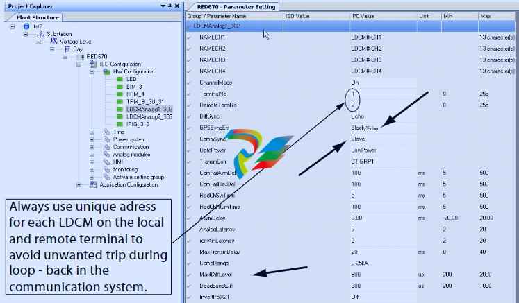
# Summary of ABB Relion® 670 Series RED670 Differential Protection Communication Network Setup and Application Guide ## I. Overview This document provides a setup and application guide for differential protection and binary signal transfer of RED670 in the ABB Relion® 670 series and other 670 series devices in telecommunication networks. It covers core contents such as synchronization methods, communication configuration, hardware modules, and fault troubleshooting, applicable to protection communication requirements of equipment like generators and lines in power systems. ## II. Core Application Scenarios and Synchronization Methods ### 1. Telecommunication Network Types and Synchronization Selection - **Symmetric/fixed route networks (Scenario I)**:Suitable for networks with fixed routes or symmetric bidirectional delays after switching. It adopts **Echo Timing** synchronization. By comparing internal device clocks and compensating with echo messages, a relative time deviation of ±1µs is achieved, supporting differential protection for up to 5 line ends . - **Unspecified route switching networks (Scenario II)**:Suitable for networks with uncertain route switching, relying on **GPS global time synchronization**. Global time is obtained through a built-in GPS receiver or IRIG-B input to ensure a clock deviation of <16µs, supporting protection reliability in complex network environments . ### 2. Key Synchronization Parameters - **Echo Timing**:Startup synchronization takes 15 seconds, with a maximum allowable communication interruption of 2 seconds (re-synchronization is required if exceeded). The protection function is blocked when clock deviation exceeds the set limit (±200-2000µs, configurable) . - **GPS Synchronization**:Cold start requires 15 minutes to search for satellites, and clock deviation can be reduced to 1µs within 1 hour. Echo Timing can be enabled as a backup after GPS interruption, and re-synchronization is required if the interruption exceeds 30 seconds . ## III. Echo Timing Function ### 1. Core Role It continuously monitors clock deviations between devices and sends echo messages at 40ms intervals to compensate for asymmetric communication delays, ensuring time synchronization accuracy for differential protection . ### 2. Asymmetric Delay Detection and Handling - **Detection Method**:Use a disturbance recorder to compare the time difference of zero-crossing points between local and remote currents to determine whether the communication system has fixed or fluctuating asymmetric delays . - **Compensation Mechanism**:Fixed asymmetric delays can be compensated by setting the `AsymDelay` parameter; fluctuating delays require switching to GPS synchronization . - **Cumulative Deviation Protection**:Monitor the accumulation of multiple small deviations (below `MaxtDiffLevel`), and block protection if exceeding 4 times to avoid maloperation . ## IV. GPS Synchronization Configuration ### 1. Startup and Calibration - **Cold Start**:The GPS antenna requires a clear view, initializes after searching for satellites (at least 4) within 15 minutes, and achieves ±1µs accuracy within 1 hour . - **Clock Synchronization**:Hardware and software clocks operate independently. During GPS synchronization, adjustment is performed in "fast/slow" modes: fast mode is suitable for rapid recovery after GPS interruption, and slow mode avoids clock jumps affecting protection . ### 2. Interruption Handling - `GPSSyncErr` is activated when GPS deviation >16µs, which can be set to block protection or switch to Echo Timing backup . - Supports redundant route monitoring; Echo Timing can continue operating if the delay after route switching is within the set range . ## V. Digital Signal Communication Configuration ### 1. Core Module: Line Data Communication Module (LDCM) - **Function**:Implements 64 kbit/s analog (current sampling) and binary signal transmission, supporting up to 4 communication channels . - **Types**:Divided into analog (CRM) and binary (CRB) modules. CRM is used for current transmission in differential protection, and CRB is used for up to 192 binary signals (e.g., control, alarm signals) . ### 2. Key Configurations - **Analog Signals**:Configure CT current sampling transmission via the PCM600 tool, supporting current summation or differential transmission for single-end dual CTs (e.g., 1.5 breaker wiring) . - **Binary Signals**:Map virtual inputs (SMBI) and outputs (SMBO) via the Signal Matrix Tool (SMT), supporting real-time transmission of 8 input/output channels . - **Redundant Channels**:Main and backup channels must have the same configuration; redundant channels automatically inherit main channel settings, with switchover delay configurable (5-500ms) to ensure seamless switching during communication interruptions . ## VI. Communication Interfaces and Network Settings ### 1. Main Interface Types | Interface Type | Protocol Standard | Application Scenario | Key Parameters | |----------------------|-------------------|----------------------------|--------------------------------------------------------------------------------| | Fiber Optic Interface | IEEE C37.94 | Long-distance, anti-interference | Multimode fiber (50/125µm, 2-3km), single-mode fiber (9/125µm, 70-110km), optical power budget 9-26dB | | Galvanic Interface | X.21 | Short-distance, leased lines | Rate 64 kbit/s, maximum cable length 100m, supporting balanced transmission | ### 2. PDH/SDH System Settings - **PDH System**:Based on 64 kbit/s channels, clock synchronization (master-slave mode) must be ensured, with maximum delay <40ms and jitter <±100µs . - **SDH System**:Based on 2 Mbit/s G.703 E1 interface, supporting structured/unstructured transmission, clock deviation <±50ppm, and buffer delay <250µs . ## VII. Fault Troubleshooting and Monitoring ### 1. Status Monitoring - **HMI Information**:Displays communication delay, number of received/transmitted messages, error codes (e.g., COMFAIL, CRCERROR), supporting real-time diagnosis of communication quality . - **Transceiver Indicators**:21-216/21-219 transceivers indicate faults via LEDs (LA for local alarm, RA for remote alarm), such as fiber signal loss and clock anomalies . ### 2. Fault Detection Methods - **Loop-back Test**:Sequentially test LDCM modules, transceivers, multiplexers, etc., through fiber or electrical loop-back to verify communication link integrity . - **Key Indicators**:Normal receive/transmit rate should reach 100%, Bit Error Rate (BER) <10⁻⁹ under normal conditions and <10⁻⁶ under disturbance . ## VIII. Key Parameters and Configuration Points ### 1. Core Parameter Settings | Parameter Category | Key Parameters | Range/Default Value | Role | |-----------------------|----------------------|------------------------------|-----------------------------------------------| | Synchronization Parameters | `MaxtDiffLevel` | 200-2000µs (default 600µs) | Maximum clock deviation threshold; protection blocks when exceeded | | Communication Parameters | `MaxTransmDelay` | 0-40ms (default 20ms) | Maximum transmission delay; protection blocks when exceeded | | Redundancy Parameters | `RedChSwTime` | 5-500ms (default 5ms) | Main-standby channel switchover delay | ### 2. Configuration Notes - Terminal numbers (`TerminalNo`) must be unique (0-255) to avoid address conflicts causing maloperation . - Fiber connections must be crossed (local Tx to remote Rx), and optical power must be within the budget (3dB margin reserved) . - Grounding must be reliable: transceivers and multiplexers share a common ground to avoid signal interference from ground loops . ## IX. Appendices and References - **Communication Requirement Specifications**:Must meet indicators such as BER, clock deviation, and delay (e.g., BER <10⁻⁸, maximum delay 40ms) . - **Related Documents**:Including operation manuals, technical reference manuals, configuration cases, etc., with the latest versions available on the ABB official website . This document provides comprehensive guidance for the reliable operation of RED670 and 670 series devices in complex telecommunication networks through clear synchronization mechanisms, communication configurations, and fault troubleshooting methods, serving as a reference for engineering design, commissioning, and maintenance personnel.
-
 AEROTECH SM Series High-Performance Stepper Motors
 -
 AEROTECH BLMSC Series Linear Motors
 -
 AEROTECH Custom Linear Motors
 -
 AEROTECH BMS Series Brushless, Slotless Rotary Motors
 -
 AEROTECH BM Series Brushless Rotary Motors
 -
 AEROTECH BLMX Series Linear Motors
 -
 AEROTECH BLMH Series Linear Motors
 -
 AEROTECH BLM Series Linear Motors
 -
 AEROTECH BLMC Series Linear Motors
 -
 AEROTECH BLMUC-143 Linear motor forcer with thermistor
 -
AEROTECH BLMUC-111 Linear motor forcer with thermistor
-
AEROTECH BLMUC-95 Linear motor forcer with thermistor
-
AEROTECH BLMUC-79 Linear motor forcer with thermistor
-
AEROTECH BLMUC Series Linear Motors
-
 AEROTECH Automation1 FLEX Distributed Amplifier Multi-Axis Servo Control System
 -
 AEROTECH Automation1 HXA4 6-Axis Hexapod Servo Drive
 -
 AEROTECH Automation1 iHXA4 6-Axis Hexapod Servo Drive with Motion Controller
 -
 AEROTECH Modular System Control Console
 -
 AEROTECH TV Series Transformers
 -
 AEROTECH TM Series Transformers
 -
 AEROTECH UFM Noise Filter Module
 -
 AEROTECH MFM Motor Filter Module
 -
 AEROTECH MPG Handwheel Pendant
 -
 AEROTECH Automation1 Multi-Axis Joystick
 -
 AEROTECH ETM Enhanced Throughput Module
 -
 AEROTECH Automation1 XL4s High-Speed, Single-Phase Linear Servo Drive
 -
 AEROTECH Automation1 XL2e Enhanced, Compact Linear Servo Drive
 -
 Automation1 iXL2e Enhanced, Compact Linear Servo Drive with Motion Controller
 -
 AEROTECH Automation1 XL5e Enhanced, Linear Servo Drive
 -
 AEROTECH Automation1 iXL5e Enhanced Linear Servo Drive with Motion Controller
 -
 AEROTECH Automation1 GI4 Laser Scan Head Controller
 -
 AEROTECH Automation1 SI4 Stepper Interface
 -
AEROTECH Automation1 XI4 Servo Interface
-
 AEROTECH AEROTECH Automation1 iXI4 Servo Interface with Motion Controller
 -
 AEROTECH Automation1 XC6e Enhanced, High-Power PWM Servo Drive
 -
 AEROTECH Automation1 iXC6e Enhanced, High-Power PWM Servo Drive with Motion Controller
 -
 AEROTECH Automation1 XC2 Compact PWM Servo Drive
 -
 AEROTECH Automation1 XC4 PWM Servo Drive
 -
 AEROTECH Automation1 GL4 Galvo Laser Scan Head Linear Drive
 -
 AEROTECH Automation1 XC2e Enhanced, Compact Servo Drive with PWM+
 -
 AEROTECH Automation1 XC4e Enhanced, PWM Servo Drive
 -
 AEROTECH Automation1 XR3 Multi-Axis Servo Drive Rack
 -
 AEROTECH Automation1 iXR3 Multi-Axis Servo Drive Rack with Motion Controller
 -
 AEROTECH Automation1 iXC2 Compact PWM Servo Drive with Motion Controller
 -
 AEROTECH Automation1 iXC2e Enhanced, Compact PWM+ Servo Drive with Motion Controller
 -
 AEROTECH Automation1 iXC4 PWM Servo Drive with Motion Controller
 -
 AEROTECH Automation1 iXC4e Enhanced, PWM Servo Drive with Motion Controller
 -
 AEROTECH Automation1 iPC Industrial PC with Motion Controller
 -
 AEROTECH EPICS & TANGO Drivers for Distributed Control Systems
 -
 AEROTECH .NET, C, Python & LabVIEW APIs Custom Application Develotpmen
 -
 AEROTECH Automation1 Industrial Ethernet Support
 -
 AEROTECH Automation1 iSMC Intelligent, Software-Based Motion Controller
 -
 AEROTECH Automation1 iXA4 1- 2- or 4-Axis PWM Servo Drive with Motion Controller
 -
 AEROTECH Automation1 XA4 1- 2- or 4-Axis PWM Servo Drive
 -
 CTI 2500-ADP2-DISC Discrete Wiring Adapter for Series 500
 -
 CTI 2500-ADP1 Analog Wiring Adapter for Series 500
 -
 CTI 2500C-RADP-RS485 Remote Base Controller Adapter for Series 500
 -
 CTI 2500C-RADP-RBC Profibus RBC Adapter for Series 500
 -
 CTI 2500C-PADP-120V 120VAC 50W Power Supply for Series 500
 -
 CTI 2500-RADP RBC Adapter for Series 500
 -
 CTI 2500-R4500 520/530/DBC Adapter for Series 500 - MATURE
 -
 CTI 2500-PADP Power Supply Adapter for Series 500
 -
 CTI 2500-IADP I/O Adapter for Series 500
 -
 CTI 2500-VP15A-N4-W7 15" Flat-Panel PC with Windows® 7 Embedded
 -
 CTI 2500S-27-1750 Slice I/O, Ethernet, RS232/485. 900MHz, 2DIO / 4UAI / 2AI
 -
 CTI 2500S-26-1750 Slice I/O, Ethernet, RS232/485. 900MHz, 8DIO / 2UAI
 -
 CTI 2500S-23-1750 Slice I/O, Ethernet, RS232/485. 900MHz, 4DI / 4DO / 2UAI / 2AO
 -
 CTI 2500S-27-1550 Slice I/O, RS232/485. 2DIO / 4UAI / 2AI
 -
 CTI 2500S-26-1550 Slice I/O, RS232/485. 8DIO / 2UAI
 -
 CTI 2500S-23-1550 Slice I/O, RS232/485. 4DI / 4DO / 2UAI / 2AO
 -
 CTI 2500S-27-1050 Slice I/O, Ethernet, 2DIO / 4UAI / 2AI
 -
 CTI 2500S-26-1050 Slice I/O, Ethernet, 8DIO / 2UAI
 -
 CTI 2500S-23-1050 Slice I/O, Ethernet, 4DI / 4DO / 2UAI / 2AO
 -
 CTI 2500C-32F-CJC 32-Pin Field Wiring Connector with Cold Junction Compensation
 -
 CTI 2500C-32F 32-Pin Field Wiring Connector
 -
 CTI 2500C-8-TC Eight Thermocouple Inputs
 -
 CTI 2500C-8-RTD Eight RTD Inputs
 -
 CTI 2500C-8-RL-FC 8 Form-C Relay Outputs
 -
 CTI 2500C-8-IDO-24V 8 Isolated 24VDC Outputs
 -
 CTI 2500C-8-IDO-120V 8 Isolated 120VAC Outputs
 -
 CTI 2500C-16-DO-24V Sixteen 24VDC Digital Outputs
 -
 CTI 2500C-16-DO-120V Sixteen 120VAC Digital Outputs
 -
.png) CTI 500C-16-IDI-24V Sixteen Isolated 24V AC/DC Digital Inputs
CTI 500C-16-IDI-24V Sixteen Isolated 24V AC/DC Digital Inputs -
 CTI 2500C-16-IDI-120V Sixteen Isolated 120V AC/DC Digital Inputs
 -
 CTI 2500C-16-DIDO-SIM Sixteen Digital Input and Output SImulator
 -
 CTI 2500C-16-DI-24V Sixteen 24V AC/DC Digital Inputs
 -
 CTI 2500C-16-DI-120V Sixteen 120V AC/DC Digital Inputs
 -
 CTI 2500C-RBC-RS485 RS485 Remote Base Controller
 -
 CTI 2500C-RBC-PRF Profibus Remote Base Controller
 -
 CTI 2500C-PS-24V-35 35-Watt DC Power Supply
 -
 CTI 2500C-PS-120V-35 35-Watt AC Power Supply
 -
 CTI 2500C-R8 Eight-Slot Base
 -
 CTI 2500C-R4 Four-Slot Base
 -
 CTI 2500C-R16 Sixteen-Slot Base
 -
 CTI 2500C-2572-B Fast Ethernet TCP/IP Adapter
 -
 CTI 2500C-J750 Compact Janus PAC with 3MB Project Memory
 -
 CTI 2500C-C300 CPU with 512K User Memory
 -
 CTI 2500C-C200 CPU with 256K User Memory
 -
 CTI 2500C-C100 CPU with 128K User Memory
 -
 CTI 2500C-8-AO 8 Analog Outputs
 -
 CTI 2500C-8-AI 8 Analog Inputs
 -
 CTI 2559-FCAL Precision Calibration Connector
 -
 CTI 2559-FPC 40-Position Screw-Terminal Connector
 -
 CTI 2500-RFC PLC to RF Modem Cable
 -
 CTI 2500-40F 40-Position Standard Screw-Terminal Connector
 -
 CTI 2505 Vibration Sensor Interface Module
 -
 CTI 2554-A 4-Channel Isolated High Speed Counter Module
 -
 CTI 2553-A 2-Channel Mag Meter Input Module
 -
 CTI 2502 2-Channel High Speed Counter Input Module
 -
 CTI 2559-TC 8-Channel Thermocouple Input Module
 -
 CTI 2556-A 16-Channel Isolated Thermocouple Input Module
 -
 CTI 2556 16-Channel Isolated Thermocouple Input Module
 -
 CTI 2551-A 8-Channel Isolated Thermocouple Input Module
 -
 CTI 2559-RTD 8-Channel RTD Input Module
 -
 CTI 2557-A 16-Channel RTD Input Module
 -
 CTI 2557 16-Channel RTD Input Module
 -
 CTI 2552-A 8-Channel Isolated RTD Input Module
 -
 CTI 2534 8-Point Form-C Relay Output Module
 -
 CTI 2532 16-Point Form-A Relay Output Module
 -
 CTI 2531 32-Point Form-A Relay Output Module
 -
 CTI 2530 8-Point Form-C Relay Output Module
 -
 CTI 2562 8-Channel Analog Output Module
 -
 CTI 2560-A 8-Channel Isolated Analog Output Module
 -
 CTI 2501 8in/4out Analog Module
 -
 CTI 2558 8-Channel Analog Input Module
 -
 CTI 2555-A 16-Channel Analog Input Module
 -
 CTI 2550-A 8-Channel Isolated Analog Input Module
 -
 CTI 2599 8/16/32-Point AC Output Module


