
samsonT 6495-2 ENTROVIS 6495 Industrial Controller
Application
Digital controller to automate industrial and process plants for general and more complex control tasks.
Fig. 1: TROVIS 6495-2 Industrial Controller
The TROVIS 6495-2 Industrial Controller is suitable for control
of continuous, on/off or pulsing final control elements (pneumatic actuators with i/p positioners, additional electric actuators, electric heating systems, refrigerating machines etc.)
Special features
• Simple menu structure with plain text display
• 4 analog inputs with filter, root extraction, function generation and measuring range monitoring
• 4 digital inputs for set point switchover, constant output
value, reversal of operating action, output tracking (DDC
backup), ramps etc
• 3 analog outputs
• 4 relay outputs for two on/off or three-step outputs or four
limit alarms
• 2 transistor outputs for fault alarms
• 1 transistor output for fault alarms
• Optional RS-232/USB and RS-485/USB interface boards
for SSP and Modbus RTU
• Degree of protection (front) IP 65
• Plug-on screw terminals
• Fixed set point control, one or two channels, internal/external switchover
• Follow-up control, one or two channels, internal/external
switchover
• Ratio control
• Cascade control, consisting of master and slave controller
• Limiting or override control
• Mixing control
• Linking of input variables (addition, subtraction, multiplication, division, mean value, minimum and maximum selection) for feedforward control or control with 1 to 4 input
variables (multi-component control)
• Operation with up to four internal set points and one external set point, either analog or via interface (SPC mode)
• Set point ramp and output ramp
• Split-range operation
• Control mode selection P/PI or PD/PID
• KP and TN adapted using the controlled variable, reference variable, manipulated variable or error signal
• Adjustable limitation of integral-action component
• Operating point preset by set point or digital input
• Control signal limitation (fixed or floating according to an
input variable)
• Operation with code number or key locking by a digital
inpu
Design and principle of operation
The TROVIS 6495-2 Industrial Controller has two independently working controllers with shared input and output
sections.
By setting the functions and parameters, the controller can be
adapted to a control task quickly. Preset basic configurations
for each control type minimize setup work for standard applications. The controller can be set up using the keys on the
housing or with the optional TROVIS-VIEW software without
requiring any additional accessories.
The controller settings are saved in a non-volatile memory,
even when the power supply fails. The two internal controllers
can be operated directly without switching. The plain-text display in English, German and French facilitates configuration
and parameterization.
Control modes
− Fixed set point control, one or two channels, internal/
external switchover
− Follow-up control, one or two channels, internal/external
switchover
− Ratio control (mixing control)
− Cascade control, consisting of master and slave controller
− Limiting or override control
Control
− Linking of input variables (addition, subtraction, multiplication, division, mean value, minimum and maximum selection) for feedforward control or control with one to four
input variables (multi-component control)
− Operation with up to four internal set points and one external set point, either analog or via interface (SPC mode)
− Set point ramp and output ramp
− Split-range operation
− Control mode selection P/PI or PD/PID
− KP and TN adapted using the controlled variable, reference variable, manipulated variable or error signal
− Adjustable limitation of integral-action component
− Operating point preset by set point or digital input
− Control signal limitation (fixed or floating according to an
input variable)
− Operation with code number or key locking by a digital
input
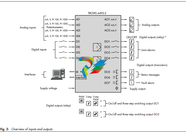
Inputs
− 4 analog inputs (AI1 to AI4)
DIP switches at the side of the housing to select current or
resistance inputs. The signal type is set depending on the
configuration:
− 0/4 to 20 mA
− 0/2 to 10 V
− Pt 100 or Pt 1000 resistance thermometer
− Filter, root extraction, function generation and measuring range monitoring
− Input 2 additionally for potentiometers
− 4 digital inputs (DI1 to DI4)
The digital inputs are controlled either by a 24 V DC voltage signal or by the transmitter supply using a floating
contact. The digital outputs can only be controlled in
groups, with DI1 and DI2 being the first group and DI3
and DI4 being the second group.
Example: internal supply for digital inputs DI1 and DI2
and external supply for digital inputs DI3 and DI4.
− Set point switchover, constant output value, reversal of operating action, output tracking (DDC backup), ramps etc
The following functions that have been defined over the C
Controller, O Output and A General settings menus
can be assigned to a digital input (see the 'Start-up and configuration' section):
− Invert digital input
− Switchover between internal set points
− Switchover to external set point
− Opening/closing cascade
− Incremental/decremental set point change
− Set point increase/decrease by constant
− Start set point ramp
− Hold set point ramp
− Invert error signal
− Control mode selection P(D)/PI(D)
− Activate operating point for P/PD controller
− Manual/automatic switchover
− Hold output
− Activate output tracking
− Increase/decrease actual value
− Activate constant output value
− Start output ramp
− Limit output rate
− Lock control keys
Outputs
− 3 analog outputs (AO1 to AO3)
The signal type is set depending on the configuration.
− 0/4 to 20 mA
− 0/2 to 10 V
The outputs AO1 to AO3 can optionally be used for other
signals as well.
− 7 digital outputs (4 relay outputs and 3 transistor
outputs)
The relay outputs can be used as follows:
− SO1 and SO2 as on/off or three-step output
− DO1 to DO4 as limit output
− DO5 and DO6 (transistor output) for status messages
− DO7 (transistor output) for fault alarms
− 4 relay outputs
for two on/off or three-step outputs or four limit alarms
− 2 transistor outputs
for status messages
− 1 transistor output
for fault alarms
− 1 supply output
The supply output can be used to supply a voltage for up
to 4 two-wire transmitters and 4 digital inputs (21 V DC,
max. 90 mA).
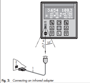
Infrared interface
Data are transmitted between the controller and the TROVISVIEW software over an infrared interface, by default
integrated into the controller and an infrared adapter (order
no. 8864-0900) connected to a computer (see the Mounting
and Operating Instructions EB 6495-2).
Communication interface
Optionally, the controller can be equipped with one of the following interface boards. The boards can also be retrofitted.
− RS-232/USB interface board
− One RS-232 interface with RJ-12 jack
− One USB interface with 5-pin mini-B port
The RS-232 data transfer uses an SSP or Modbus RTU
protocol. The memory pen-64 can be used with controllers
fitted with an RS-232/USB interface board to load data
configured in TROVIS-VIEW or transferred from another
controller.
− RS-485/USB interface board
− RS-485 interface (4 terminals) and
− USB interface (5-pin mini-B port)
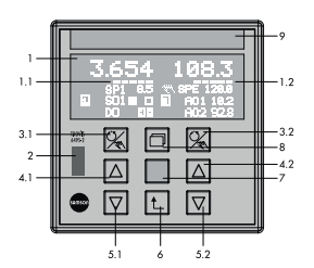
Operation
Display and operating controls
The device has nine operating keys, of which three are assigned to each controller channel. Depending on the selected
control type, one or two controllers are activated. The readings and controls of the controller [1] are located on the left
half of the device and on the right half for controller [2] (or
optionally vice versa). The row of keys in the middle is used
for both controllers.
Fig. 5: Display and operating controls
Operating level
After the supply voltage has been switched on, the controller
is in operating level.
The readings of the controlled variable, the reference variable
and the manipulated variable for each controller as well as a
bar graph for error are indicated on the display (1). Depending on the configuration, status alarms of the digital inputs
and outputs can be shown. The operating menu allows set
points to be switched and control parameters to be changed.
The two rows at the bottom of the display can be assigned as
desired. Numerous signals and interim outputs relating to the
internal controllers can be selected. For example, the values or
a bar graph of two outputs in split-range operation can be
displayed.
Configuration and parameterization
The controller is adapted to the selected application in the
configuration level. The configuration items are arranged in
hierarchical menus. All settings are displayed as plain text.
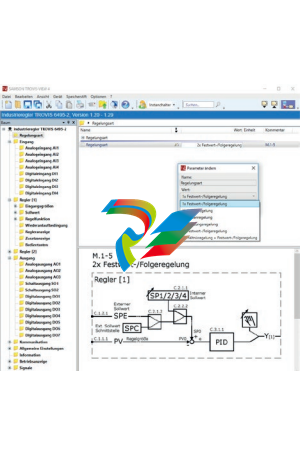
Operation using TROVIS-VIEW
Controller settings (see Fig. 6)
Configuration settings and parameters can conveniently be
adjusted, documented and transmitted using the optional
TROVIS-VIEW software. Working in TROVIS-VIEW is similar
to working in Windows® Explorer. TROVIS-VIEW includes a
trend viewer for start-up that records the process data. Input
and output variables are displayed in a clear structure.
The TROVIS-VIEW software can be delivered on a CD-ROM,
if required. For further information on TROVIS-VIEW refer to
Data Sheet T 6661.
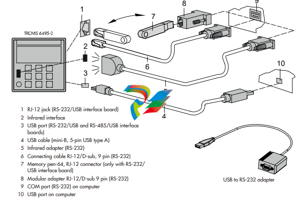
Data transmission (see Fig. 7)
Î Ordering numbers (see Table 3)
Data can be exchanged between the TROVIS-VIEW software
and the controller in various ways:
– Data transmission using the infrared interface (11) and an
infrared adapter (14)
– Data transmission using the optional interface board with
RS-232 and USB connections: data can be transmitted
over a conventional cable connection (either with a USB
cable (13) or a connecting cable (15)) or using a memory
pen (16).
– To integrate the controller into a communications network,
the controller can be fitted with an optional RS-485 interface board. The interface board has a USB connection
which can be used to transfer data using TROVIS-VIEW
-
 HIRSCHMANN MSM20-M2M2M2M2SY9HH9E Ethernet media modul
 -
 HIRSCHMANN SPIDER-PL-20-05T1999999TWVHHHH Industrial Ethernet Rail Switch
 -
 Hirschmann SPIDER-PL-20-07T1M2M299TWVHHHH Industrial ETHERNET Rail Switch
 -
.png) Hirschmann (Belden) RS20-1600M2M2SDAEHC09.1.00 DIN-rail managed industrial Fast Ethernet switch
Hirschmann (Belden) RS20-1600M2M2SDAEHC09.1.00 DIN-rail managed industrial Fast Ethernet switch -
 Hirschmann (Belden) RS30-1602O6O6TDAPHC09.1.00 DIN-rail managed industrial Ethernet switch
 -
 Hirschmann (Belden) RS30-2402O6T1SDAPHH09.0.13 DIN-rail industrial Ethernet switch
 -
Hirschmann (Belden) SPIDER-PL-20-04T1S29999TY9HHHH Ethernet DIN-rail switch
-
 HIRSCHMANN RS20-1600T1T1SDAUHX Switch
 -
 HIRSCHMANN BRS42-0012OOOO-SPCZ99HHSES industrial switch
 -
 Hirschmann RS20-0800S2S2TDHPHH09.0.14 Fast Ethernet DIN rail switch.
 -
 HIRSCHMANN MM20-Z6Z6M2M2SAHH Hybrid Fast Ethernet Media Module
 -
 HIRSCHMANN MM20-Z6Z6T1T1SAHH hot-swappable hybrid Fast Ethernet Media Module
 -
 HIRSCHMANN MM20-P9P9T1T1SAHH Hybrid Fast Ethernet Media Module
 -
 HIRSCHMANN MM20-M4T1T1T1SAHH Hybrid Fast Ethernet Media Module
 -
 HIRSCHMANN MM20-M4M4T1T1SAHH Hybrid Fast Ethernet Media Module
 -
 HIRSCHMANN MM20-M2M2M2M2SZHH Ethernet media module
 -
HIRSCHMANN MM20-M2M2M2M2SAHH Ethernet media module
-
 HIRSCHMANN MM20-T1T1T1T1EBH 4-port Fast Ethernet Copper Cable Media Module
 -
HIRSCHMANN MM20-T1T1T1T1SAHH 4-port Fast Ethernet Copper Cable Media Module
-
HIRSCHMANN MM20-T1T1T1T1SAHH 4-port Fast Ethernet Copper Cable Media Module
-
 HIRSCHMANN MM20-Z6Z6EBH Hot-swappable fast Ethernet media module
 -
 HIRSCHMANN MM20-Z6Z6SAHH Ethernet media module
 -
HIRSCHMANN MM20-Z6Z6Z6Z6EBH Industrial Media Module
-
 MSM40-T1T1T1TZ9HH9E99.9.99 HIRSCHMANN Switch
 -
 HIRSCHMANN MS20-0800SAAEHC / MS20-0800SAAEHC0 8-port modular Layer 2 management Ethernet switch
 -
 Hirschmann RSPM20-4T14T1SZ9HHS9 Switch RSPM20-4T14T1SZ9HHS9
 -
 HIRSCHMANN RS20-1600M2M2SDAEHH09.1. RS20/30/40 Managed Switch configurator
 -
HIRSCHMANN RS20-1600M2M2SDAEHX09.0.00 Ethernet switch
-
 HIRSCHMANN BELDEN SPIDER-PL-20-07T1M2M299TY9HHHH / SPIDERPL2007T1M2M299TY9HHHH
 -
HIRSCHMANN MM3-1FXS2/3TX1 Switching Board Module
-
 HIRSCHMANN RSPE30-24044O7T99-ECCP999HHSE2A08.1.00 Industrial-grade fanless management-type Ethernet switch
 -
 HIRSCHMANN RS30-1602OOZZSDAEHC09.1.00 DIN-rail-mounted managed Layer 2 Ethernet switch
 -
 HIRSCHMANN MACH104-20TX-F Managed 24-port Full Gigabit 19" Switch
 -
 HIRSCHMANN Switch RS20-0800M4M4SDAE
 -
Hirschmann RS30-1602O6O6SDAEHH09.1. Management-type Ethernet switch
-
 Hirschmann RS30-1602OOZZSDAEHC09.0.10 Open rack-style Ethernet switch
 -
 HIRSCHMANN RSPE30-24044O7T99-SCCV999HHSI2SXX.X.XX High-Availability Seamless Redundancy
 -
HIRSCHMANN RSPE30-24044O7T99-SCCZ999HHSE2A DIN-rail Ethernet switch
-
HIRSCHMANN MM2-4TX1-EEC switch
-
HIRSCHMANN MSM40-T1T1T1T1TZ9HH9E99.9.99 Module
-
 HIRSCHMANN RS20 Rail Switch RS20-0400S4T1SDAEHC07.1.01
 -
 HIRSCHMANN M4-FAST8-SFP Fast Ethernet media module
 -
 HIRSCHMANN RS20-0400M2T1SDAP Managed Fast-Ethernet-Switch
 -
 HIRSCHMANN BELDEN SPIDER II 8TX/1FX EEC Industrial Ethernet Rail Switch
 -
HIRSCHMANN MM3-2FXS2/2TX1
-
 HIRSCHMANN RS2-4TX/1FX EEC Industrial Ethernet Rail Switch
 -
 RS30-0802O6O6SDAEHC09.0.10 HIRSCHMANN Switch
 -
 HIRSCHMANN m4-8TP-RJ45 Ethernet Media Module
 -
 HIRSCHMANN MSP30-24040SCZ9URHHE3A switch
 -
 Hirschmann rack MS30-1602SAAPHC
 -
 HIRSCHMANN RS2-FX/FX Industrial Switch Module
 -
Rs1txfx - Hirschmann - Rs1-Tx/Fx Rail Switch
-
RS20-0800S2S2SDAEHC09.1.00 HIRSCHMANN Commutator
-
 Hirschmann EAGLE20 TX/TX Industrial Security Router
 -
 Hirschmann SPIDER-SL-20-04T1S29999SY9HHHH Industrial Switch
 -
 HIRSCHMANN MAR1040-4C4C4C4C9999SMMHRHHXX.X. Gigabit Ethernet Switch configurator
 -
 Hirschmann MAR1040 Industrial Switch
 -
 HIRSCHMANN BELDEN RS30-1602O6O6SDAE
 -
Hirschmann RS20-1600M2M2SDAUHC Ethernet DIN rail switch
-
 HIRSCHMANN OCTOPUS 24M industrial switch
 -
 HIRSCHMANN RS20-1600T1T1SDAE Management-type Ethernet switch
 -
 HIRSCHMANN RS20-1600T1T1SDAUHH industrial switch
 -
HIRSCHMANN RS20-0800M2M2SDAPHC09.0.04 switch
-
 Hirschmann MR 8-03 24V DC Industrial Modular Bridge/Router
 -
 HIRSCHMANN RS20-0400M2T1SDAPHC08.0.01 Managed Switch
 -
 MACH1130 Hirschmann Industrial Switch
 -
 HIRSCHMANN 943824-002 SPIDER 5TX Industrial Ethernet Switch
 -
 HIRSCHMANN RS30-0802O6O6SDAEHC09.1.00 Managed Industrial Switch
 -
 HIRSCHMANN RS20-0400M2M2TDAEHC04.0.01 Industrial Switch
 -
 HIRSCHMANN BRS20-0600Z6Z6-STCZ99HHSES Industrial Switch
 -
 HIRSCHMANN MACH104-20TX-FR-L3P Industrial Ethernet Switch
 -
 HIRSCHMANN RS40-0009CCCCEDBPHH06.0.01 Industrial Switch
 -
 HIRSCHMANN RS2-3TX/2FX EEC Industrial Ethernet Switch
 -
 Hirschmann MACH 1020/1030 Fast/Gigabit Rack Mount Switches
 -
HIRSCHMANN RS20-0800M2M2SDAPHC09.0.14 Industrial Switch
-
 HIRSCHMANN RS20-1600T1T1SDAEHC09.0.04 Industrial Switch
 -
 HIRSCHMANN RSB20-0800T1T1EAABHH Industrial Switch
 -
 HIRSCHMANN MACH4002-48+4G-L3E Industrial Backbone Switch
 -
 HIRSCHMANN RS20-0400S2T1SDAE Industrial Managed Switch
 -
HIRSCHMANN RS20-0800S2T1SDAUHC Industrial Switch
-
 HIRSCHMANN RS20-2400S4S4SDAEHC09.0.14 industrial switch
 -
 HIRSCHMANN OS20-001200T5T5T5- TBBZ999HHNE3S 08.1.00 industrial switch
 -
HIRSCHMANN OS20-001200T5T5T5- TBBZ999HHNE3S 08.1.00 industrial switch
-
 HIRSCHMANN RS40-0009CCCCSDAEHH09.0.14 switch
 -
 Hirschmann RS20-1600T1T1SDAUHC Management-type Ethernet Switch
 -
 Hirschmann M1-8SFP Switche
 -
Hirschmann Industrial Ethernet Ruggedized Switch MACH1000 Family
-
 Basler Electric, Solid State Protective Relay, BE1-60
 -
BASLER ELECTRIC SR4A-2B15B3A Static Voltage Regulator
-
.png) BASLER ELECTRIC EXCITER DIODE MONITOR EDM-200
BASLER ELECTRIC EXCITER DIODE MONITOR EDM-200 -
.png) BASLER ELECTRIC DECS125-15-B2C5 DIGITAL EXCITATION CONTROL SYSTEM V 2.0.9
BASLER ELECTRIC DECS125-15-B2C5 DIGITAL EXCITATION CONTROL SYSTEM V 2.0.9 -
 BASLER ELECTRIC BE1-851 OVERCURRENT PROTECTION RELAY MECHANISM
 -
 Basler Electric BE1-51A / BE151A
 -
 Basler Electric BE1-40Q Loss of Excitation Relay
 -
 Basler Electric BE1-87G Variable Percentage Differential Relay
 -
 Basler Electric BE1-11 Protection System I5A3M2P2N0EA00
 -
 BASLER ELECTRIC DECS-200-1C Digital Excitation Control System
 -
 Basler Electric / Kohler BE1-11g Generator Protection Relay G5A3M2J2N0E000
 -
BASLER ELECTRIC DECS125-15 DIGITAL EXCITATION CONTROL SYSTEM
-
 BASLER ELECTRIC BE1-951 OverCurrent Protecton System
 -
Basler Electric DECS-200-1L Digital Excitation Control System
-
 Basler Electric DGC-2020HD-5NS1DNSBA Digital Genset Controller -
 -
 BASLER ELECTRIC BE1-81T1EE1WA0N1F / BE181T1EE1WA0N1F
 -
 BASLER ELECTRIC BE1-25M1EA6PN5R1F / BE125M1EA6PN5R1F
 -
 BASLER ELECTRIC DECS-250-LN1SN1N DIGITAL EXCITATION CONTROL SYSTEM
 -
Basler Electric DECS-250-CN2CN 1N Digital Excitation Control System Unit
-
 BASLER ELECTRIC DECS-300-C0N0 DIGITAL EXCITATION CONTROL SYSTEM
 -
 BASLER ELECTRIC BE1-87T-A1E-A1J-D0S1F / BE187TA1EA1JD0S1F
 -
BASLER ELECTRIC BE1-11-G6D1M0J2P0E000 Protection System
-
 BASLER ELECTRIC BE1-GPS100-E4N1H1N GENERATOR PROTECTION SYSTEM
 -
 Jaquet Relay card (Auxiliary module) FTV 3090 377Z-03985
 -
 Jaquet Trip Chain Control card FTBU 3034 377Z-05030
 -
 Jaquet with input card -E04 FTFU 3024 -E04 377Z-05855
 -
 Jaquet with input card -E03 FTFU 3024- E03 377Z-03983
 -
 Jaquet FTFU 3024- E02 377Z-03982 with input card -E02
 -
 Jaquet FTFU 3024-E01 377Z-03981 with input card -E01
 -
 Hirschmann RS20-2400T1T1SDAE Industrial Managed Ethernet Switch
 -
 Hirschmann BELDEN EAGLE30-04022O6TT999SCCV9HSE3F
 -
 Hirschmann MM3-2FXS2/2TX MICE Media Module
 -
 Hirschmann RS20-1600M2M2SDAPHC08.0.05 Industrial Managed Switch
 -
 Hirschmann OZD Profi 12M G12-1300 PRO Fieldbus Repeater
 -
Hirschmann SPIDER 4TX/1FX-ST EEC Industrial Ethernet Switch
-
 Hirschmann MM2-2FXM3/2TX1 MICE Media Module
 -
 Hirschmann RS20-2400M2M2SDAPHC09.0.14 Industrial Switch
 -
 Hirschmann RS20-0400M2M2SDAEHC07.1.05 OpenRail Switch
 -
 Hirschmann OZD Profi 12M G12-EEC Fieldbus Repeater
 -
HIRSCHMANN MDA422-1/2-3.5c-23/46 sensor
-
Hirschmann RS30-2402T1T1SDAUHC Managed Industrial Switch


