
GEInstallation and Maintenance Manual Bently Nevada™ Asset Condition Monitoring
Additional Information
Notice:
This manual does not contain all the information required to operate and maintain
the product. Refer to the following manuals for other required information.
3500 Monitoring System Rack Configuration and Utilities Guide
(129777-01)
• guidelines for using the 3500 Rack Configuration software for setting the operating
parameters of the module
• guidelines for using the 3500 test utilities to verify that the input and output
terminals on the module are operating properly
3500 Monitoring System Computer Hardware and Software Manual
(128158-01)
• instructions for connecting the rack to 3500 host computer
• procedures for verifying communication
• procedures for installing software
• guidelines for using Data Acquisition / DDE Server and Operator Display Software
• procedures and diagrams for setting up network and remote communications
3500 Field Wiring Diagram Package (130432-01)
• diagrams that show how to hook up a particular transducer
• lists of recommended wiring
Operation and Maintenance Manuals for all the modules installed in the
rack
Product Disposal Statement
Customers and third parties, who are not member states of the European Union, who are
in control of the product at the end of its life or at the end of its use, are solely
responsible for the proper disposal of the product. No person, firm, corporation,
association or agency that is in control of product shall dispose of it in a manner that is
in violation of any applicable federal, state, local or international law. Bently Nevada LLC
is not responsible for the disposal of the product at the end of its life or at the end of its
use.
1. Receiving and Handling Instructions
This will be a short overview of the entire section.
1.1 Receiving Inspection
Visually inspect the system for obvious shipping damage. If you detect shipping
damage, file a claim with the carrier and submit a copy to Bently Nevada, LLC.
1.2 Handling and Storage Considerations
Proper handling and storing of printed circuit boards is extremely critical. Circuit
boards contain devices that are susceptible to damage when exposed to
electrostatic charges. Damage caused by obvious mishandling of the board will
void the warranty. To avoid damage, observe the following precautions in the
order given.
Application Advisory
Machinery protection will be lost when
you remove all power from the rack.
• Do not discharge static electricity onto the circuit board. Avoid tools or
procedures that would subject the circuit board to static damage.
Some possible causes of static damage include ungrounded soldering
irons, nonconductive plastics, and similar materials.
• Use a suitable grounding strap (such as 3M Velostat® No. 2060) to
ground yourself before handling or performing maintenance on a
printed circuit board.
• Transport and store circuit boards in electrically conductive bags or
foil.
• Use extra caution during dry weather. Relative humidity less than 30%
tends to multiply the accumulation of static charges on any surface.
When performed properly, you may remove modules from or install modules into
the rack while power is applied to the rack. Refer to << Section reference to
“Module Installation in section 4 >> for the proper procedure
2. General Information
Monitoring and computerized vibration information systems provide the
information you need to assess the mechanical condition of rotating and
reciprocating machinery. These systems continuously measure and monitor
various supervisory parameters and provide crucial information for early
identification of machinery problems such as imbalance, misalignment, shaft
crack, and bearing failures. As such, these systems are an efficient and effective
means of satisfying plant management, engineering, and maintenance concerns
for:
• Increasing plant safety by minimizing the occurrence of hazardous
conditions or catastrophic failures.
• Improving product quality by minimizing process variances caused by
improperly operating equipment.
• Maximizing plant availability by servicing only those machines that
require it and providing more efficient turnarounds.
• Reducing plant operating costs by minimizing unplanned shutdowns
and by making more efficient use of maintenance resources.
For protection of critical machinery, we highly recommend that you permanently
install continuous monitoring systems. The term "protection" means that the
system can shut down machinery on alarm, without human interaction. These
systems include applicable transducers, each with its own dedicated monitoring
circuitry and alarm setpoints. The 3500 Monitoring System is the newest addition
to the family of continuous monitoring systems offered by Bently Nevada, LLC.
2.1 3500 Monitoring System
The 3500 is a full-feature monitoring system whose design incorporates the latest
in proven processor technology. In addition to meeting the above stated criteria,
the 3500 adds benefit in the following areas:
• Enhanced operator information
• Improved integration to plant control computer
• Reduced installation and maintenance cost
• Improved reliability
• Intrinsic Safety (IS) option
The following sections discuss these benefits in more detail.
2.1.1 Enhanced Operation Information
The 3500 design includes features to both enhance the operator's information
and present this information so that the operator may easily interpret it. These
features include:
• Improved data set
- Overall amplitude
- Probe gap voltage
- 1X amplitude and phase
- 2X amplitude and phase
- Not 1X amplitude
• Windows®-based Operator Display Software
• Data displayed at multiple locations
2.1.2 Improved Integration to Plant Control Computer
The 3500 improves integration to the plant control computer with:
• Communication Gateways supporting multiple protocols
• Time synchronized vibration and process information
2.1.3 Reduced Installation and Maintenance Costs
The 3500 system provides the following cost-saving features:
• Reduced cabling costs
• Downward product compatibility
• Improved space utilization
• Easier configuration
• Reduced spare parts
• Improved serviceability
2.1.4 Improved Reliability
The 3500 offers several features to improve system reliability.
• Redundant power supplies available
• Triple Modular Redundant (TMR) monitors and relay cards available
• Redundant Gateway and Display Modules permitted
2.1.5 Intrinsic Safety Option
If you wish to monitor equipment that is located in hazardous atmospheres, the
3500 Monitoring System has a range of I/O modules with internal zener barriers.
These modules provide an Intrinsically Safe interface between the 3500 rack and
the transducers located in the hazardous area.
2.1.6 Multiple Output Interfaces
You can conveniently adjust monitor options (such as full scale ranges,
transducer inputs, recorder outputs, alarm time delays, alarm voting logic, and
relay configuration) in the field via software. Modular system design employs
plug-in components which allow easy servicing and expansion.
The following three independent interfaces are available with the 3500 system:
• Data Manager Interface (Transient Data Interface External or Dynamic
Data Interface External)
• Configuration/Data port
• Communications Gateway (support for Programmable Logic
Controllers, Process Control Computers, Distributed Control Systems,
and PC-based Control Systems)
These interfaces allow you to easily view monitored parameters and their
statuses in the following ways:
• System 1® Software
• Bently Nevada™ 3500 Operator Display Software
• Remote display panel
• DCS or PLC display
Convenient front panel coaxial connectors provide dynamic transducer signals
and allow you to connect diagnostic or predictive maintenance instruments.
2.2 Common Features
The common features of the modules in the 3500 rack include hot insertion or
removal of modules and external and internal termination of the wiring.
2.2.1 Hot Insertion or Removal of Modules
When performed properly, you can remove and replace any module while the
system is under power without affecting the operation of any unrelated modules.
If the rack has 2 power supplies, removing or inserting a power supply will not
disrupt the operation of the 3500 rack. See <<Section reverence: “Module
Installation in section 4 >> for the proper procedure.
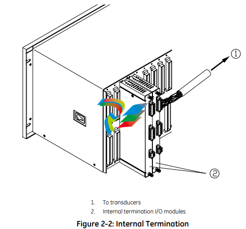
2.2.2 External and Internal Termination
External termination uses multi-conductor cables to connect the I/O modules to
the terminal blocks. These blocks simplify connecting many wires to the rack in
tight areas. External termination is not available on I/O modules with internal
zener barriers.

Internal termination lets you connect transducers directly to the I/O modules.
3500 System Components
The 3500 Monitoring System consists of modules that fit into a rack. Figure 2-3
shows a full-size 3500 system rack and system components. Note that the fullsize rack has 14 monitor slot positions. The Mini-rack (not shown) is similar, but
has 7 monitor slot positions to the right of the power supplies and Rack Interface
Module.
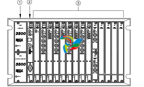
1. 1 or 2 power supplies
2. Rack Interface Module (standard, Transient Data Interface, (TDI), Triple Modular Redundant (TMR) and TMR TDI)
3. Monitoring slot positions:
- Monitor module
- Keyphasor® module (2 maximum)
- Relay module
- Communication Gateway module
- Display module. For the System Face Mount you must install the Display Interface Module in Slot 15.
- 3500/04-01 Earthing Module. Intallations that use Inernal Barrier I/Os require 1 Earthing Module per rack.
Figure 2-3: 3500 Rack (Full-Size)
The following sections list the function of each module. Refer to the individual
operation and maintenance manuals for available options, detailed description,
operation and maintenance.
2.3.1 Weatherproof Housing
The weatherproof housing protects the 3500 rack from adverse environmental
effects, such as excessive moisture, dirt and grime, and even unclean air. The
weatherproof housing will not accommodate a Display Unit or VGA Display.
2.3.2 Rack
2 types of 3500 racks are available: the full-size 19-inch rack and the compact 12-
inch Mini-rack. Each rack requires you to install the Power Supplies and Rack
Interface Module (RIM) in specific locations. The full-size version offers 14
additional rack positions and the Mini-rack offers 7 additional rack positions. You
may use these positions to install any combination of modules. Both racks
support Standard (non-redundant) and Triple Modular Redundant (TMR)
configurations
Application Advisory
The TMR system will restrict the
location of certain modules.
2.3.3 Power Supply
The Power Supply is a half-height module available in ac and dc versions. You
can install 1 or 2 power supplies in the rack. Each power supply can power a fully
loaded rack. When you install 2 power supplies in a rack, the supply in the lower
slot acts as the primary supply and the supply in the upper slot acts as the
backup supply. If the primary supply fails, the backup supply will provide power to
the rack without interrupting rack operation. The 3500 design allows you to
install any combination of power supply types.
Overspeed Detection and TMR Monitors require dual power supplies.
2.3.4 Rack Interface Module
The Rack Interface Module (RIM) is a full-height module that communicates with
the host (computer), a Bently Nevada™ Communication Processor, and the other
modules in the rack. The Rack Interface Module also maintains the System Event
List and the Alarm Event List. You can daisy-chain this module to the Rack
Interface Modules in other racks and to the Data Acquisition / DDE Server
Software. The 3500 Monitoring System Computer Hardware and Software Manual
shows how to daisy chain the Rack Interface Modules together. Rack Interface
Modules are available in Standard, Triple Modular Redundant and Transient Data
Interface versions.
2.3.5 Communication Gateway Module
The Communication Gateway Module is a full-height module that allows external
devices (such as a DCS or a PLC) to retrieve information from the rack and to set
up portions of the rack configuration. You can install more than one
Communication Gateway Module in the same rack. Communication Gateway
Modules are available for a variety of network protocols.
2.3.6 Monitor Module
The Monitor Modules are full-height modules that collect data from a variety of
transducers. You can install any combination of Monitor Modules in the 3500
rack.
2.3.7 Relay Module
Relay Modules provide relays that you can configure to close or open based on
channel statuses from other monitors in the 3500 rack. Relay modules are
available in 4-channel, 16-channel, and 4-channel Triple Modular Redundant
(TMR) versions.
The TMR Relay Module is a half-height 4-channel module that operates in a TMR
system. 2 half-height TMR Relay Modules must operate in the same slot. If you
remove the upper or lower Relay Module or the system declares one of the
modules as Not OK, then the other Relay Module will control the Relay I/O Module.
2.3.8 Keyphasor® Module
The Keyphasor Module is a half-height module that provides power for the
Keyphasor transducers, conditions the Keyphasor signals, and sends the signals
to the other modules in the rack. The Keyphasor Module also calculates the rpm
values sent to the host (computer) and external devices (DCS or PLC) and provides
buffered Keyphasor outputs. Each Keyphasor Module supports 2 channels. You
may place up to 2 Keyphasor Modules in a 3500 rack for a maximum of 4
Keyphasor channels. If you use 2 Keyphasor Modules, you must place them in the
same full-height slot and the modules will share a common I/O module.
2.3.9 Display Module
The 3500 system offers multiple display options.
The Display Interface Module can display rack data on an LCD-based Interface
unit or a 3rd-party Modbus® based display unit.
The VGA Display Module will display rack data on certain touch screen VGA
Displays.
The Integrated PC display is a complete rack mount touch screen PC pre-loaded
with rack configuration software and display utilities.
2.3.10 Earthing Module
The Earthing Module is a full-height module that provides a low resistance
connection (must be less than 1 Ω) from the 3500 rack to the plant’s intrinsically
safe earth ground. The module operates in conjunction with the 3500 internal
zener barrier I/O modules. Your application will require 1 Earthing Module per rack
when internal barrier I/O modules are used.
2.4 Standard Rack Relay Options
You can configure the standard (or non-TMR) 3500 rack to have individual relays,
bussed relays, or a combination of individual and bussed relays.
2.4.1 Individual Relays
A rack with individual relays contains 1 or more relay cards for each monitor
module. You can configure the monitor and relay modules within a 3500 rack in
many ways.
Example 1: The application uses 1 relay module 1 monitor module
Table 2-1: 1 Relay Module Used With 1 Monitor Module
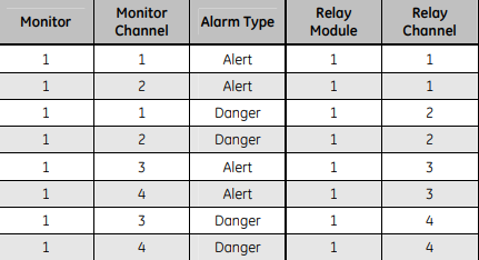
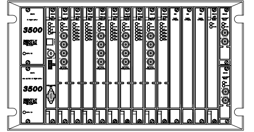
Figure 2-4: Typical Standard 3500 Rack with Individual Relays (Full-Size Rack Shown)
2.4.2 Bussed Relays
In the Bussed Relays configuration a number of monitor channels share a single
relay. Use the Rack Configuration Software to define the combination of alarms
that will trigger the relay. Figure 2-5 shows a typical Bussed Relay layout for a
standard 3500 rack. You can [place the monitors and relay modules in any slot as
long as you link the monitors to the relay module in the Rack Configuration
Software
3.7.4 Additional Notes
• Larger scale factors are less susceptible to EMI than smaller scale factors.
• Larger full-scales are less susceptible to EMI than smaller full-scale.
• Monitors with narrow bandwidth filter configurations are less susceptible to
EMI than monitors configured with wide bandwidth.
• Larger Keyphasor® or hysteresis settings are less susceptible to EMI than
smaller hysteresis settings.
• Shorter Alarm delay times may increase monitor susceptibility to transient
EMI.
• Environments with higher levels of EMI than tested may cause unpredictable
monitor readings and may cause system malfunction.
3.8 Set Rack Jumpers and Switches
Set the following jumpers and switches before operating the rack:
• Rack address switch (on the front of the Rack Interface Module)
• Transducer jumpers on each I/O Module, as required
• Certain I/O Modules have switches to control their mode of operation.
Examples include:
- RIM and Comm Gateway I/O’s that support both RS232 and
RS422 have a protocol selection switch
- Overspeed and non-TMR Relay I/O’s have Normally
Energized/De-energized Relay mode switches
- Comm Gateway I/O’s that support RS485 have termination
mode switches
• Setup phone connection to rack / host (if you use an internal or
external modem)
- Phone cable to internal modem in rack
-
 Beckhoff C6640-0040 Control Cabinet Industrial PC 7-Slot
 -
 BECKHOFF CONTROL CABINET INDUSTRIAL PC - C6930-1062-0050
 -
 Beckhoff Automation EtherCAT Terminal EK1100 EK1122
 -
 Beckhoff CP6533-0001-0060 IPC
 -
 Beckhoff EK9500 | EtherNet/IP™ Bus Coupler
 -
 Beckhoff CP6202-1047-0050 - An industrial-grade embedded panel computer.
 -
 Beckhoff C6650-0040 Industrial PC
 -
 BECKHOFF CX5230-0185 / 000119805 PLC Module
 -
 BECKHOFF EL4732 | EtherCAT Terminal, 2-channel analog output, voltage, ±10 V, 16 bit, oversampling
 -
 Beckhoff CP6202-0001-0010 Economy Built-In Panel
 -
 Beckhoff AX5206-0000-0202 Digital Compact Servo Drives 2-channel
 -
 Beckhoff CP6606-0001-0020 7-inch Economy Panel PC
 -
 Beckhoff CPU basic module CX2020-0155 + power supply module CX2100-0004
 -
 Beckhoff CP2913-000 Multi-Touch Display
 -
 Beckhoff CP6500-1012-0060 14250369 Control Cabinet
 -
 Beckhoff CP7902-0001-0000 Economy Control Panel with DVI/USB Extended interface
 -
 Beckhoff C6920-0010 Control cabinet Industrial PC
 -
 BECKHOFF C3640-0050 Build-in Industrial PCs
 -
 Beckhoff KL6023-0000 KL6023 EnOcean Wireless-Adapter
 -
 Kollmorgen AKM54G-ANC2DB00 servo motor
 -
 Kollmorgen AKD-P00606-NBCN-0000 Servo Drive
 -
Kollmorgen S200 Series S20350-VTS SERVO DRIVE
-
 KOLLMORGEN AKD-P00606-NBCC-I000 SERVO DRIVE
 -
 Kollmorgen MV65WKS-CE310/22PB Servo Drive Control Module
 -
 Kollmorgen S20360-VTS-021 Servo Drive
 -
 KOLLMORGEN CR06550 High-precision digital servo amplifier
 -
 KOLLMORGEN DBL5N01050-03S-VV0-S40 3-Phase AC Synchronous Brushless Servo Motor
 -
 KOLLMORGEN S70301-NANANA-024 SERVO DRIVE
 -
 Kollmorgen S20360-VTS S200 Series Servo Drive
 -
 Kollmorgen RBE-03011-A00 Brushless Frameless Servo Motor
 -
 KOLLMORGEN AKD-T00306-NBAN-0000 INPUT SERVO DRIVE
 -
 KOLLMORGEN S700 Servo Controller S70302-NANANA
 -
 Kollmorgen AKD-P00607-NBEC-0000 400/480VAC 4.40KVA Servo Drive.
 -
 KOLLMORGEN S70102-NANANA SERVO DRIVE
 -
 KOLLMORGEN AKM21E-ANSNEH02 PM Servo Motor & PRD-AMPE25EB-00 Servo Drive Array
 -
 KollMorgen SC1R06260 Servo Drive 1.4/2.2 KVA 115230 Vac
 -
 Kollmorgen AKD-P00306-NBAN-0000 Servo Drive
 -
Kollmorgen TTB2-2042-3052-A DC Motor Industrial Drive 5.5A 185 oz/in
-
 KOLLMORGEN SERVOSTAR 610-AS SERVO AMPLIFIER_SERVOSTAR610AS_S61001
 -
 KOLLMORGEN PRD-0016400P-10 & PRD-0016600D-30 Axis Control System Modules
 -
KOLLMORGEN Seidel DBL5N01700-03S-000-S40 Servo Motor
-
 Hirschmann RS20-1600M2T1SDAEHH03.1.02 Rail Switch
 -
 Hirschmann BRS30-24TX Industrial Rail Switch
 -
 Hirschmann RSPM20-4T14T1EV9HHS999.9.99 Managed Ethernet Switch
 -
 Hirschmann BELDEN RS40-0009CCCCSDAPHH09.0.14 / RS400009CCCCSDAPHH09014
 -
Hirschmann RS40 Rail Switch RS40-0009CCCCSDAE
-
 Hirschmann BELDEN RS30-0802T1T1SDAP / RS300802T1T1SDAP Fully Managed Layer 2 Compact Rail Switch
 -
 Hirschmann BELDEN RS20-0800M2M2SDAUHH / RS200800M2M2SDAUHH
 -
 Hirschmann EAGLE30-04022O6TT999SCCY9HSE3F Industrial Firewall Router Switch
 -
 Hirschmann RS20-1600T1T1SDAEHH09.0.14 RS20 Rail Mount Ethernet Switch
 -
 Hirschmann EAGLE0200T1T1TDDY90000HHE05.3.03 Industrial Security Router
 -
Hirschmann - BELDEN MIPP-AD-1L9P
-
 HIRSCHMANN RSPM20-4Z64Z6TV9HHS9 942 106-999 RAIL SAFETY SWITCH
 -
 HIRSCHMANN FIBEROPTIC MODULE FIP P/N: OZDFIPG3T
 -
 HIRSCHMANN RS20-1600M2M2SDAUHH Ethernet rack-mounted switch
 -
 HIRSCHMANN BELDEN RS20-0400T1T1SDAEHH04.0.01 / RS200400T1T1SDAEHH04001
 -
HIRSCHMANN MM2-4FXM3 MICE Media Module
-
HIRSCHMANN RS20-0800M2M2SDAE Industrial Ethernet Rail Switch
-
 Hirschmann RS20-2400T1T1SDAP / RS20-2400T1T1SDAPHH05.0.02
 -
 GE MLJ1005B010H00C MLJ Digital Synchromism Check
 -
 ALSTOM MICROTECH DX21-M2 Digital Excitation Controller
 -
HIRSCHMANN BRS20-1200ZZZZ-STCY99HHSES
-
 HIRSCHMANN MM3-4FXM2 MICE Media Module
 -
Hirschmann RSB20-0800T1T1SAABHH 8Port ENet Rail Switch RSB20
-
 Hirschmann MACH102-8TP Ethernet Switch
 -
 SAACKE DDZ-M marine steam pressure atomizer
 -
 SAACKE SKV-A marine rotary cup atomizer
 -
 SAACKE Seavis HMI05e
 -
 Kollmorgen MMC-SD-2.0-230 Servo Drive 100-240VAC 2KW 10A Output 3PH 100-240VAC
 -
 Kollmorgen Servo drive CR10550
 -
 Kollmorgen AKD-P01207-NACN-0054 Servo Driver
 -
 Kollmorgen S406M-CA-036 Servostar
 -
.png) Kollmorgen AKD-B02407-NAAN-0000 Digital Servo Drive
Kollmorgen AKD-B02407-NAAN-0000 Digital Servo Drive -
 Kollmorgen SERVOSTAR S406AM-CA Digital Servo Drive
 -
 KOLLMORGEN SERVOSTAR 603-AS SERVO AMPLIFIER_SERVOSTAR603AS_S60301
 -
Kollmorgen S700 Servo Controller (S70602-NANANA-NA)
-
 Kollmorgen MPK411 controller
 -
 KOLLMORGEN MMC-SD-1.3-460-D Smart Drive
 -
 KOLLMORGEN AKM21C-CKB2AA-00 / AKM21CCKB2AA00 Servomotor
 -
 BECKHOFF AX5106-0000-0200 | Digital Compact Servo Drives 1-channel
 -
 BECKHOFF C3620-0000 INDUSTRIAL COMPUTER (MOTORSHELVES)
 -
 Beckhoff EK1960-0000 TwinSAFE Compact Controller
 -
 Beckhoff C6930-0050 Control Cabinet Industrial PC
 -
 Beckhoff CP7711-0001-0030 Industrial Computer Detection
 -
 Beckhoff CX1001-0111 Embedded PC CPU Module
 -
 Beckhoff C6017-0020 | Ultra-compact Industrial PC
 -
 Beckhoff EK1322 | 2-port EtherCAT P junction with feed-in
 -
 Beckhoff CP2219-0010 Panel
 -
 BECKHOFF C6015-0020 ULTRA COMPACT INDUSTRIAL PC
 -
 BECKHOFF CX2030-0120/Standard CPU Module Embedded PC Windows PLC controller
 -
 Beckhoff CP7721-1090-0020 Panel PC
 -
 Beckhoff PC CPU Module CX5130-0175
 -
 Beckhoff C6920-0050 Control Cabinet
 -
 Beckhoff EL6631 EtherCAT 2-Port Communication Interface, Profinet RT Controller
 -
 Beckhoff CP6202-0001-0060 touch screen panel PC
 -
 Beckhoff CP3916-1002-0000 Multi-Touch Control Panel
 -
 Beckhoff EP1809-0021 | EtherCAT Box, 16-channel digital input, 24 V DC, 3 ms, M8Preferred type
 -
 Beckhoff CX8190 PLC Embedded Industrial PC Ethernet Controller
 -
 Beckhoff CX2100-0914 Power Supply for External
 -
 Beckhoff Automation CP6906-0001-0000 HMI
 -
 Beckhoff EP7342-0002 Module
 -
 Beckhoff CX1020-0112 / CX1100-0910 / CX1020-N010 / CX1100-0003 Windows CPU
 -
 Beckhoff EP7211-0034 EtherCAT Box 1 Channel Motion Interface
 -
 Beckhoff C6240-0030 Control cabinet Industrial PC
 -
 beckhoff motherboard CB1052-0004 CB1052-0004
 -
 Beckhoff AX2006-AS Servo Drive / Variable Frequency Drive
 -
BECKHOFF CP6207-0001-0020 NSMP
-
 Beckhoff C6930-1142-0060 Industrial Computer
 -
 Beckhoff FC7501-0000 interface card
 -
 Beckhoff CX5140-0175 Embedded PC PLC CPU CX5140 Industrial Controller
 -
 Beckhoff CP7802-1100-0010: High-End IP65 Control Panel with DVI/USB Extended Interface
 -
BECKHOFF CP3716-1058-0010 CONTROL PANEL
-
 Beckhoff AX8108-0000 Single-Axis Module
 -
 Beckhoff CU8851-0000 | USB extension, USB Extended 2.0 receiver box
 -
Beckhoff C6017-0030 | Ultra-compact Industrial PC
-
 Beckhoff CX1001-0120/CX10010120.cx1000-n001.cx1000-n000 System Overview
 -
 Beckhoff CPU Module CX5140-0155/4GB CPU Module
 -
 Beckhoff CP6533-0001-005: Built-in Panel PC with High-Definition Multi-Touch Control
 -
 Beckhoff EL5042 | EtherCAT Terminal, 2-channel encoder interface, BiSS® C
 -
 Beckhoff C6920-1080-0040: Premium Control Cabinet Industrial PC
 -
 Beckhoff C6920-0060 | Control cabinet Industrial PC
 -
 Beckhoff Embedded-PC CX5010-1121
 -
 Beckhoff CB3050-0010 Mainboard Motherboard
 -
 Beckhoff PLC module CX1020-0000 Basic CPU module (service phase)
 -
 Beckhoff CP7812-1056-0010 15" Multitouch Display Control Panel
 -
 Beckhoff CX5120-0115 /2GB Controller Module
 -
 Beckhoff CP7201-1000-0000 Industrial Panel PC
 -
 Beckhoff Servo Motor AM8061-0JH1-0000


