
schneiderEnterasys® 800-Series Fast Ethernet/Gigabit Ethernet Switches
Hardware Installation Guide
08H20G4-24, 08H20G4-24P
08H20G4-48, 08H20G4-48P
08G20G2-08, 08G20G2-08P
08G20G4-24, 08G20G4-24P
08G20G4-48, 08G20G4-48P
Electrical Hazard: Only qualified personnel should perform installation procedures.
Riesgo Electrico: Solamente personal calificado debe realizar procedimientos de instalacion.
Elektrischer Gefahrenhinweis: Installationen sollten nur durch ausgebildetes und qualifiziertes Personal
vorgenommen werden.
Regulatory Compliance Information
Federal Communications Commission (FCC) Notice
This device complies with Part 15 of the FCC rules. Operation is subject to the following two conditions: (1) this device may not
cause harmful interference, and (2) this device must accept any interference received, including interference that may cause
undesired operation.
NOTE: This equipment has been tested and found to comply with the limits for a class A digital device, pursuant to Part 15 of
the FCC rules. These limits are designed to provide reasonable protection against harmful interference when the equipment is
operated in a commercial environment. This equipment uses, generates, and can radiate radio frequency energy and if not
installed in accordance with the operator’s manual, may cause harmful interference to radio communications. Operation of this
equipment in a residential area is likely to cause interference in which case the user will be required to correct the interference
at his own expense.
WARNING: Changes or modifications made to this device which are not expressly approved by the party responsible for
compliance could void the user’s authority to operate the equipment.
Industry Canada Notice
This digital apparatus does not exceed the class A limits for radio noise emissions from digital apparatus set out in the Radio
Interference Regulations of the Canadian Department of Communications.
Le présent appareil numérique n’émet pas de bruits radioélectriques dépassant les limites applicables aux appareils
numériques de la class A prescrites dans le Règlement sur le brouillage radioélectrique édicté par le ministère des
Communications du Canada.
Class A ITE Notice
WARNING: This is a Class A product. In a domestic environment this product may cause radio interference in which case the
user may be required to take adequate measures.
Clase A. Aviso de ITE
ADVERTENCIA: Este es un producto de Clase A. En un ambiente doméstico este producto puede causar interferencia de radio
en cuyo caso puede ser requerido tomar medidas adecuadas.
Klasse A ITE Anmerkung
WARNHINWEIS: Dieses Produkt zählt zur Klasse A ( Industriebereich ). In Wohnbereichen kann es hierdurch zu
Funkstörungen kommen, daher sollten angemessene Vorkehrungen zum Schutz getroffen werden.
VCCI Notice
This is a class A product based on the standard of the Voluntary Control Council for Interference by Information Technology
Equipment (VCCI). If this equipment is used in a domestic environment, radio disturbance may arise. When such trouble
occurs, the user may be required to take corrective actions.
Hazardous Substances
This product complies with the requirements of European Directive, 2002/95/EC, Restriction of Hazardous Substances (RoHS)
in Electrical and Electronic Equipment.
European Waste Electrical and Electronic Equipment (WEEE) Notice

Safety Information
Class 1 Laser Transceivers
The single mode interface modules use Class 1 laser transceivers.
Read the following safety information before installing or operating these modules.
The Class 1 laser transceivers use an optical feedback loop to maintain Class 1 operation limits. This control loop eliminates the
need for maintenance checks or adjustments. The output is factory set, and does not allow any user adjustment. Class 1 Laser
transceivers comply with the following safety standards:
• 21 CFR 1040.10 and 1040.11 U.S. Department of Health and Human Services (FDA).
• IEC Publication 825 (International Electrotechnical Commission).
• CENELEC EN 60825 (European Committee for Electrotechnical Standardization).
When operating within their performance limitations, laser transceiver output meets the Class 1 accessible emission limit of all
three standards. Class 1 levels of laser radiation are not considered hazardous.
When the connector is in place, all laser radiation remains within the fiber. The maximum amount of radiant power exiting the
fiber (under normal conditions) is -12.6 dBm or 55 x 10-6 watts.
Removing the optical connector from the transceiver allows laser radiation to emit directly from the optical port. The maximum
radiance from the optical port (under worst case conditions) is 0.8 W cm-2 or 8 x 10³ W m2
sr-1.
Do not use optical instruments to view the laser output. The use of optical instruments to view laser output increases eye
hazard. When viewing the output optical port, power must be removed from the network adapter.
Safety Compliance
Warning: Fiber Optic Port Safety
Avertissment: Ports pour fibres optiques - sécurité sur le plan optique
Warnhinweis: Faseroptikanschlüsse - Optische Sicherheit
When using a fiber optic media expansion module, never look at the transmit laser
while it is powered on. Also, never look directly at the fiber TX port and fiber cable
ends when they are powered on.
Ne regardez jamais le laser tant qu’il est sous tension. Ne regardez jamais
directement le port TX (Tramsmission) à fibres optiques et les embouts de câbles à
fibres optiques tant qu’ils sont sous tension.
Niemals ein Übertragungslaser betrachten, während dieses eingeschaltet ist.
Niemals direkt auf den Faser-TX-Anschluß und auf die Faserkabelenden schauen,
während diese eingeschaltet sind
Enterasys Networks, Inc. Firmware License Agreement
BEFORE OPENING OR UTILIZING THE ENCLOSED PRODUCT,
CAREFULLY READ THIS LICENSE AGREEMENT.
This document is an agreement (“Agreement”) between the end user (“You”) and Enterasys Networks, Inc., on behalf of itself
and its Affiliates (as hereinafter defined) (“Enterasys”) that sets forth Your rights and obligations with respect to the Enterasys
software program/firmware (including any accompanying documentation, hardware or media) (“Program”) in the package
and prevails over any additional, conflicting or inconsistent terms and conditions appearing on any purchase order or other
document submitted by You. “Affiliate” means any person, partnership, corporation, limited liability company, other form of
enterprise that directly or indirectly through one or more intermediaries, controls, or is controlled by, or is under common
control with the party specified. This Agreement constitutes the entire understanding between the parties, with respect to the
subject matter of this Agreement. The Program may be contained in firmware, chips or other media.
BY INSTALLING OR OTHERWISE USING THE PROGRAM, YOU REPRESENT THAT YOU ARE AUTHORIZED TO ACCEPT
THESE TERMS ON BEHALF OF THE END USER (IF THE END USER IS AN ENTITY ON WHOSE BEHALF YOU ARE
AUTHORIZED TO ACT, “YOU” AND “YOUR” SHALL BE DEEMED TO REFER TO SUCH ENTITY) AND THAT YOU
AGREE THAT YOU ARE BOUND BY THE TERMS OF THIS AGREEMENT, WHICH INCLUDES, AMONG OTHER
PROVISIONS, THE LICENSE, THE DISCLAIMER OF WARRANTY AND THE LIMITATION OF LIABILITY. IF YOU DO NOT
AGREE TO THE TERMS OF THIS AGREEMENT OR ARE NOT AUTHORIZED TO ENTER INTO THIS AGREEMENT,
ENTERASYS IS UNWILLING TO LICENSE THE PROGRAM TO YOU AND YOU AGREE TO RETURN THE UNOPENED
PRODUCT TO ENTERASYS OR YOUR DEALER, IF ANY, WITHIN TEN (10) DAYS FOLLOWING THE DATE OF RECEIPT
FOR A FULL REFUND.
IF YOU HAVE ANY QUESTIONS ABOUT THIS AGREEMENT, CONTACT ENTERASYS NETWORKS, LEGAL
DEPARTMENT AT (603) 952-5000.
You and Enterasys agree as follows:
1. LICENSE. You have the non-exclusive and non-transferable right to use only the one (1) copy of the Program provided in
this package subject to the terms and conditions of this Agreement.
2. RESTRICTIONS. Except as otherwise authorized in writing by Enterasys, You may not, nor may You permit any third
party to:
(a) Reverse engineer, decompile, disassemble or modify the Program, in whole or in part, including for reasons of error
correction or interoperability, except to the extent expressly permitted by applicable law and to the extent the parties
shall not be permitted by that applicable law, such rights are expressly excluded. Information necessary to achieve
interoperability or correct errors is available from Enterasys upon request and upon payment of Enterasys’ applicable
fee.
(b) Incorporate the Program in whole or in part, in any other product or create derivative works based on the Program, in
whole or in part.
(c) Publish, disclose, copy reproduce or transmit the Program, in whole or in part.
(d) Assign, sell, license, sublicense, rent, lease, encumber by way of security interest, pledge or otherwise transfer the
Program, in whole or in part.
(e) Remove any copyright, trademark, proprietary rights, disclaimer or warning notice included on or embedded in any
part of the Program.
3. APPLICABLE LAW. This Agreement shall be interpreted and governed under the laws and in the state and federal courts
of the State of New Hampshire without regard to its conflicts of laws provisions. You accept the personal jurisdiction and venue
of the State of New Hampshire courts. None of the 1980 United Nations Convention on the Limitation Period in the International
Sale of Goods, and the Uniform Computer Information Transactions Act shall apply to this Agreement.
4. EXPORT RESTRICTIONS. You acknowledge and agree that the Licensed Materials are subject to the export control laws
and regulations of the United States, including but not limited to the Export Administration Regulations (EAR), the International
Traffic in Arms Regulations (ITAR), and the sanction regimes of the U.S. Department of Treasury, Office of Foreign Assets
Control’s Foreign Assets Control Regulations (FACR). You agree that You will comply with these laws and regulations.
You agree that You will not, without prior U.S. Government authorization, export, reexport, or transfer the Licensed Materials,
either directly or indirectly, to any country subject to a U.S. trade embargo or sanction (e.g. Cuba, N. Korea, Iran, Syria, Sudan)
or to any resident or national of said countries, or to any person, organization, or entity on any of the restricted parties lists
maintained by the U.S. Departments of State, Treasury, or Commerce. In addition, You agree that You will not export, reexport
or transfer the Licensed Materials to any end-user engaged in activities, or for any end-use, directly or indirectly related to the
design, development, production, use, or stockpiling of weapons of mass destruction, e.g. nuclear, chemical, or biological
weapons, and the missile technology to deliver them.
5. UNITED STATES GOVERNMENT RESTRICTED RIGHTS. The enclosed Program (i) was developed solely at private
expense; (ii) contains “restricted computer software” submitted with restricted rights in accordance with section 52.227-19 (a)
through (d) of the Commercial Computer Software-Restricted Rights Clause and its successors, and (iii) in all respects is
proprietary data belonging to Enterasys and/or its suppliers. For Department of Defense units, the Program is considered
commercial computer software in accordance with DFARS section 227.7202-3 and its successors, and use, duplication, or
disclosure by the U.S. Government is subject to restrictions set forth herein.
6. DISCLAIMER OF WARRANTY. EXCEPT FOR THOSE WARRANTIES EXPRESSLY PROVIDED TO YOU IN WRITING
BY ENTERASYS, ENTERASYS DISCLAIMS ALL WARRANTIES, EITHER EXPRESS OR IMPLIED, INCLUDING BUT NOT
LIMITED TO IMPLIED WARRANTIES OF MERCHANTABILITY, SATISFACTORY QUALITY, FITNESS FOR A PARTICULAR
PURPOSE, TITLE AND NON-INFRINGEMENT WITH RESPECT TO THE PROGRAM. IF IMPLIED WARRANTIES MAY NOT
BE DISCLAIMED BY APPLICABLE LAW, THEN ANY IMPLIED WARRANTIES ARE LIMITED IN DURATION TO THIRTY
(30) DAYS AFTER DELIVERY OF THE PROGRAM TO YOU.
7. LIMITATION OF LIABILITY. IN NO EVENT SHALL ENTERASYS OR ITS SUPPLIERS BE LIABLE FOR ANY
DAMAGES WHATSOEVER (INCLUDING, WITHOUT LIMITATION, DAMAGES FOR LOSS OF BUSINESS, PROFITS,
BUSINESS INTERRUPTION, LOSS OF BUSINESS INFORMATION, SPECIAL, INCIDENTAL, CONSEQUENTIAL, OR
RELIANCE DAMAGES, OR OTHER LOSS) ARISING OUT OF THE USE OR INABILITY TO USE THE PROGRAM, EVEN IF
ENTERASYS HAS BEEN ADVISED OF THE POSSIBILITY OF SUCH DAMAGES. THIS FOREGOING LIMITATION SHALL
APPLY REGARDLESS OF THE CAUSE OF ACTION UNDER WHICH DAMAGES ARE SOUGHT.
THE CUMULATIVE LIABILITY OF ENTERASYS TO YOU FOR ALL CLAIMS RELATING TO THE PROGRAM, IN
CONTRACT, TORT OR OTHERWISE, SHALL NOT EXCEED THE TOTAL AMOUNT OF FEES PAID TO ENTERASYS BY
YOU FOR THE RIGHTS GRANTED HEREIN.
8. AUDIT RIGHTS. You hereby acknowledge that the intellectual property rights associated with the Program are of critical
value to Enterasys, and, accordingly, You hereby agree to maintain complete books, records and accounts showing (i) license
fees due and paid, and (ii) the use, copying and deployment of the Program. You also grant to Enterasys and its authorized
representatives, upon reasonable notice, the right to audit and examine during Your normal business hours, Your books, records,
accounts and hardware devices upon which the Program may be deployed to verify compliance with this Agreement, including
the verification of the license fees due and paid Enterasys and the use, copying and deployment of the Program. Enterasys’ right
of examination shall be exercised reasonably, in good faith and in a manner calculated to not unreasonably interfere with Your
business. In the event such audit discovers non-compliance with this Agreement, including copies of the Program made, used
or deployed in breach of this Agreement, You shall promptly pay to Enterasys the appropriate license fees. Enterasys reserves
the right, to be exercised in its sole discretion and without prior notice, to terminate this license, effective immediately, for failure
to comply with this Agreement. Upon any such termination, You shall immediately cease all use of the Program and shall return
to Enterasys the Program and all copies of the Program.
9. OWNERSHIP. This is a license agreement and not an agreement for sale. You acknowledge and agree that the Program
constitutes trade secrets and/or copyrighted material of Enterasys and/or its suppliers. You agree to implement reasonable
security measures to protect such trade secrets and copyrighted material. All right, title and interest in and to the Program shall
remain with Enterasys and/or its suppliers. All rights not specifically granted to You shall be reserved to Enterasys.
10. ENFORCEMENT. You acknowledge and agree that any breach of Sections 2, 4, or 9 of this Agreement by You may cause
Enterasys irreparable damage for which recovery of money damages would be inadequate, and that Enterasys may be entitled
to seek timely injunctive relief to protect Enterasys’ rights under this Agreement in addition to any and all remedies available at
law.
11. ASSIGNMENT. You may not assign, transfer or sublicense this Agreement or any of Your rights or obligations under this
Agreement, except that You may assign this Agreement to any person or entity which acquires substantially all of Your stock
assets. Enterasys may assign this Agreement in its sole discretion. This Agreement shall be binding upon and inure to the benefit
of the parties, their legal representatives, permitted transferees, successors and assigns as permitted by this Agreement. Any
attempted assignment, transfer or sublicense in violation of the terms of this Agreement shall be void and a breach of this
Agreement.
12. WAIVER. A waiver by Enterasys of a breach of any of the terms and conditions of this Agreement must be in writing and
will not be construed as a waiver of any subsequent breach of such term or condition. Enterasys’ failure to enforce a term upon
Your breach of such term shall not be construed as a waiver of Your breach or prevent enforcement on any other occasion.
13. SEVERABILITY. In the event any provision of this Agreement is found to be invalid, illegal or unenforceable, the validity,
legality and enforceability of any of the remaining provisions shall not in any way be affected or impaired thereby, and that
provision shall be reformed, construed and enforced to the maximum extent permissible. Any such invalidity, illegality, or
unenforceability in any jurisdiction shall not invalidate or render illegal or unenforceable such provision in any other
jurisdiction.
14. TERMINATION. Enterasys may terminate this Agreement immediately upon Your breach of any of the terms and
conditions of this Agreement. Upon any such termination, You shall immediately cease all use of the Program and shall return
to Enterasys the Program and all copies of the Program.
About This Guide
This guide provides an overview, installation and troubleshooting instructions, and specifications
for the Enterasys 800-Series Fast/Gigabit Ethernet switches.
For information about the Command Line Interface (CLI) set of commands used to configure and
manage the Enterasys 800-Series switches, refer to the Enterasys 800-Series CLI Reference.
For information about the Web User Interface (Web UI) used to configure and manage the
Enterasys 800-Series switches, refer to the Enterasys 800-Series Web UI Reference.
This preface provides an overview of this guide and the Enterasys 800-Series manual set, and
explains the symbols used throughout this guide.
Who Should Use This Guide
This guide is intended for a network administrator responsible for installing and setting up the
switches.
How to Use This Guide
Read through this guide completely to familiarize yourself with its contents and gain an
understanding of the features and capabilities of the Ethernet switch. A general knowledge of data
communications networks is helpful when setting up the switch.
This guide provides information about the following:
Related Documents
The following manuals can be obtained from the World Wide Web in Adobe Acrobat Portable
Document Format (PDF) at the following site:
Electrical Hazard: Only qualified personnel should perform installation procedures.
Riesgo Electrico: Solamente personal calificado debe realizar procedimientos de instalacion.
Elektrischer Gefahrenhinweis: Installationen sollten nur durch ausgebildetes und qualifiziertes
Personal vorgenommen werden.
For... Refer to...
An overview of the 800-Series features. Chapter 1, Introduction
Instructions to install the 800-Series on a flat surface or in a
standard 19-inch rack.
Chapter 2, Installation
Troubleshooting installation problems and diagnosing
network/operational problems using the LEDs.
Chapter 3, Troubleshooting
Specifications, environmental requirements, and physical
properties of the 800-Series and optional redundant power
supplies.
Appendix A, Specifications
Temperature, humidity, and airflow guidelines, with dust
mitigation and airborne chemical prevention.
Appendix B, Environmental Guidelines
Conventions Used in This Guide
The following conventions are used in this guide:
Note: Calls the reader’s attention to any item of information that may be of special importance.
Caution: Contains information essential to avoid damage to the equipment.
Precaución: Contiene información esencial para prevenir dañar el equipo.
Achtung: Verweißt auf wichtige Informationen zum Schutz gegen Beschädigungen.
Electrical Hazard: Warns against an action that could result in personal injury or death due to an
electrical hazard.
Riesgo Electrico: Advierte contra una acción que pudiera resultar en lesión corporal o la muerte
debido a un riesgo eléctrico.
Elektrischer Gefahrenhinweis: Warnung vor sämtlichen Handlungen, die zu Verletzung von
Personen oder Todesfällen – hervorgerufen durch elektrische Spannung – führen können!
Warning: Warns against an action that could result in personal injury or death.
Advertencia: Advierte contra una acción que pudiera resultar en lesión corporal o la muerte.
Warnhinweis: Warnung vor Handlungen, die zu Verletzung von Personen oder gar Todesfällen
führen können!
This chapter introduces the Enterasys 800-Series Fast/Gigabit Ethernet switches.
Overview
The Enterasys 800-Series Fast/Gigabit Ethernet switches are store and forward switches that can
be adapted and scaled to help meet your network requirements.
You can also use a redundant power supply with these switches to help prevent downtime due to
an internal power supply failure in the switch or AC power source.
You can install the switches on a flat surface or into a standard 19-inch rack, and configure the
switch functions using the Web User Interface, Command Line Interface commands, and/or
SNMP.
The Enterasys 800-Series switch can connect to Ethernet networks or workstations through RJ45
connectors, SFP ports, or Gigabit Ethernet ports, depending on your model’s configuration. The
SFP ports support optional pluggable transceivers, which are hot swappable.
For pluggable transceiver compatibility and specifications, refer to the datasheet at
http://www.enterasys.com/products/transceivers-ds.pdf.
Table 1-1 lists the number of ports and port types for the Enterasys 800-Series switches.
For information about... Refer to page...
Overview 1-1
Features 1-6
Table 1-1 800-Series Switch Port Types
800-Series Model Ports
08H20G4-24
(see Figure 1-1 on page 1-3)
• Twenty-Four 10/100 Mbps Copper ports.
• Two Combo 10/100/1000 Mbps Copper ports, 100/1000
Mbps SFP ports.
• Two 100/1000 Mbps SFP ports.
08H20G4-24P
(see Figure 1-2 on page 1-3)
• Twenty-Four 10/100 Mbps Copper PoE+ ports.
• Two Combo 10/100/1000 Mbps Copper ports, 100/1000
Mbps SFP ports.
• Two 100/1000 Mbps SFP ports.
08H20G4-48
(see Figure 1-3 on page 1-3)
• Fourty-Eight 10/100 Mbps Copper ports.
• Two Combo 10/100/1000 Mbps Copper ports, 100/1000
Mbps SFP ports.
• Two 100/1000 Mbps SFP ports.
Switch Configuration Using CLI Commands
The CLI commands enable you to perform complete switch configuration management tasks. For
CLI command set information and how to configure the switch, refer to the Enterasys 800-Series
CLI Reference.
Fan Operation on the 800-Series
The 800-Series switches support three unique fan control mechanisms.
1. The 08G20G2-08, 08G20G4-24, and 08H20G4-48 switches will turn on their fans with the initial
boot-up procedure and will turn off their fans when the room temperature is below 32° C
(89.6° F). If the room temperature rises above 36° C (96.8° F), these switches’ internal fans will
turn on again.
2. The 08G20G4-24P, 08G20G4-48, 08G20G4-48P, 08H20G4-24P, and 08H20G4-48P switches will
never turn their fans off. Instead their fans will toggle between high and low revolution
speeds. During the initial boot-up procedure or when the room temperature is above 36° C
(96.8° F), these fans will operate at a high revolution speed. If the room temperature falls
below 32° C (89.6° F), then these switches’ fans will operate at a low revolution speed.
3. The 08G20G2-08P switch will automatically turn the internal fans off when the PoE feature
provides a load within 60W and the room temperature is below 30° C (86° F). During the
initial boot-up procedure, when the PoE load is over 60W, or when the room temperature is
above 36° C (96.8° F), the switch’s fans will automatically turn on.
The 08H20G4-24 is the only switch in this series that can operate between 0° C (32° F) and 50° C
(122° F) without the need for internal fans.
Standards Compatibility
The Copper ports are compliant with the following standards and operations:
• IEEE 802.3
• IEEE 802.3u
• IEEE 802.3ab
• IEEE 802.3ad
• Support Half/Full-Duplex operations
• Auto-negotiation, Auto MDI/MDIX
• IEEE 802.3x Flow Control support for Full-Duplex mode, Back Pressure when Half-Duplex
mode, and Head-of-line blocking prevention
• IEEE 802.3an compliance
The SFP ports are compliant with the following standards and operations:
• IEEE 802.3z
• IEEE 802.3x Flow Control support for Full-Duplex mode
• Auto-negotiation for Full-Duplex control operation
Guidelines for Flat Surface Installation
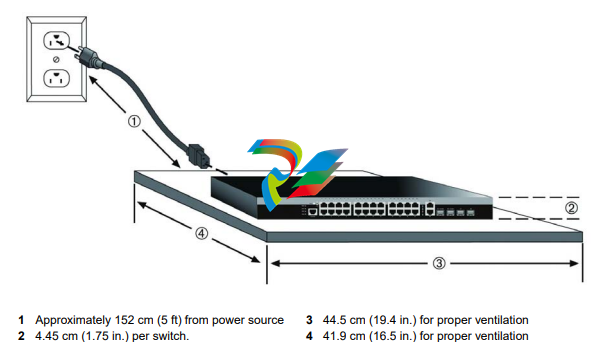
Locate the switch within 182.88 cm (6 ft) of its power source and on a surface as shown in
Figure 2-1 on page 2-3. If an optional redundant power system is going to be installed and
connected to the 14-pin Redundant Power Supply input connector on the rear of the switch, refer
to “Installing and Connecting a Redundant Power System” on page 2-21.
Proceed to “Connecting AC Power” on page 2-21 for power connection instructions.
Figure 2-1 Area Guidelines for Switch Installation on Flat Surface
Mounting the 24 and 48 Port Switches
Install the switch in the rack mount kit and mount the switch to a 48.26-centimeter (19-inch) rack
or other secure location, as described in Installing the Switch into a Rack.
Installing the Switch into a Rack
To install the switch in a 19-inch rack, you need:
• Two rackmount brackets and mounting screws (rackmount kit) shipped with the switch.
• Four customer-supplied screws to attach the switch to a standard 19-inch rack.
Caution: To ensure proper ventilation and prevent overheating, leave a minimum clearance space
of 5.1 cm (2.0 in.) at the left and right of the switch.
Do not connect the switch to the AC power source until instructed to do so later in the installation
process.
Precaución: Para asegurar una buena ventilación y evitar que el sistema se sobrecaliente, deje un
espacio mínimo de 5.1 cm (2 pulgadas) con respecto a los lados y a la parte posterior del aparato.
No conecte el dipositivo a la fuente primaria hasta que no se le indique
Guidelines for Rackmount Installation
The installation site must be within reach of the network cabling and meet the requirements listed
below:
• Appropriate grounded power receptacles must be located within 152 cm (5 ft) of the location.
• A temperature of between 0°C (32°F) and 50°C (122°F) must be maintained at the installation
site with fluctuations of less than 10°C (18°F) per hour.
Attaching the Brackets and Installing in a Rack
The following section explains how to attach brackets to a 24 and 48 port switch and then how to
install this switch in a rack. There are eight 24 and 48 port switches that can be installed following
this procedure. They are the 08H20G4-24, 08H20G4-24P, 08H20G4-48, 08H20G4-48P, 08G20G4-24,
08G20G4-24P, 08G20G4-48, and 08G20G4-48P. Proceed as follows to install the switch into a
19-inch rack:
1. Attach the rackmount brackets to the switch, as shown in Figure 2-2, using the eight M3x6
mm flathead screws shipped with the switch.
Figure 2-2 Attaching the Rackmount Brackets
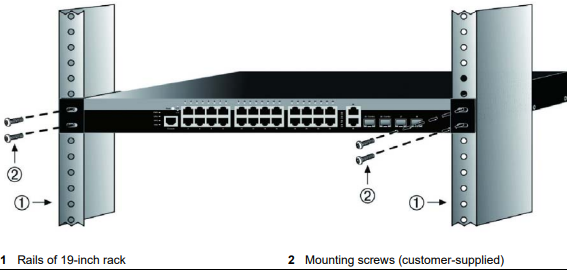
2. With the mounting brackets attached, position the switch between the vertical frame members
of the 19-inch rack as shown in Figure 2-3. Then fasten the switch securely to the frame using
four customer-supplied mounting screws.
Note: To ensure proper ventilation and prevent overheating, leave a minimum clearance space of
5.1 cm (2.0 in.) at the left and right of the switch.
Warning: Before rack-mounting the switch, ensure that the rack can support it without
compromising stability. Otherwise, personal injury and/or equipment damage may result.
Advertencia: Antes de montar el equipo en el rack, asegurarse que el rack puede soportar su peso
sin comprometer su propia estabilidad, de otra forma, daño personal o del equipo puede ocurrir.
Warnhinweis: Überzeugen Sie sich vor dem Einbau des Gerätes in das Rack von dessen
Stabilität, ansonsten könnten Personenschäden oder Schäden am Gerät die Folge sein.
Note: Do not install the rubber feet if you are rack mounting the switch.
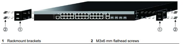
Figure 2-3 Fastening the Switch to the Rack
Mounting the 8 Port Switches
The following mounting options are available for the 8 port switch. Each requires that you
purchase a separate mounting kit. Proceed to mount the switch in your desired location using one
of the procedures described in this section:
Install the switch in a table mount kit and mount the switch under a table, as described in
“Installing the Switch Under a Table” on page 2-10.
Install the switch in a wall mount kit and mount the switch on a wall, as described in “Installing
the Switch on a Wall” on page 2-12.
Install the switch in a lockbox kit and mount the switch on a wall, as described in “Installing the
Switch in the Lockbox and Mounting on a Wall.” on page 2-14.
Positioning and Securing One or Two 8 Port Switches
This section details how to mount the 08G20G2-08 and 08G20G2-08P switches into the optional
rack mount kit (D2-RMT
-
 Hirschmann RS20-1600M2T1SDAEHH03.1.02 Rail Switch
 -
 Hirschmann BRS30-24TX Industrial Rail Switch
 -
 Hirschmann RSPM20-4T14T1EV9HHS999.9.99 Managed Ethernet Switch
 -
 Hirschmann BELDEN RS40-0009CCCCSDAPHH09.0.14 / RS400009CCCCSDAPHH09014
 -
Hirschmann RS40 Rail Switch RS40-0009CCCCSDAE
-
 Hirschmann BELDEN RS30-0802T1T1SDAP / RS300802T1T1SDAP Fully Managed Layer 2 Compact Rail Switch
 -
 Hirschmann BELDEN RS20-0800M2M2SDAUHH / RS200800M2M2SDAUHH
 -
 Hirschmann EAGLE30-04022O6TT999SCCY9HSE3F Industrial Firewall Router Switch
 -
 Hirschmann RS20-1600T1T1SDAEHH09.0.14 RS20 Rail Mount Ethernet Switch
 -
 Hirschmann EAGLE0200T1T1TDDY90000HHE05.3.03 Industrial Security Router
 -
Hirschmann - BELDEN MIPP-AD-1L9P
-
 HIRSCHMANN RSPM20-4Z64Z6TV9HHS9 942 106-999 RAIL SAFETY SWITCH
 -
 HIRSCHMANN FIBEROPTIC MODULE FIP P/N: OZDFIPG3T
 -
 HIRSCHMANN RS20-1600M2M2SDAUHH Ethernet rack-mounted switch
 -
 HIRSCHMANN BELDEN RS20-0400T1T1SDAEHH04.0.01 / RS200400T1T1SDAEHH04001
 -
HIRSCHMANN MM2-4FXM3 MICE Media Module
-
HIRSCHMANN RS20-0800M2M2SDAE Industrial Ethernet Rail Switch
-
 Hirschmann RS20-2400T1T1SDAP / RS20-2400T1T1SDAPHH05.0.02
 -
 GE MLJ1005B010H00C MLJ Digital Synchromism Check
 -
 ALSTOM MICROTECH DX21-M2 Digital Excitation Controller
 -
HIRSCHMANN BRS20-1200ZZZZ-STCY99HHSES
-
 HIRSCHMANN MM3-4FXM2 MICE Media Module
 -
Hirschmann RSB20-0800T1T1SAABHH 8Port ENet Rail Switch RSB20
-
 Hirschmann MACH102-8TP Ethernet Switch
 -
 SAACKE DDZ-M marine steam pressure atomizer
 -
 SAACKE SKV-A marine rotary cup atomizer
 -
 SAACKE Seavis HMI05e
 -
 Kollmorgen MMC-SD-2.0-230 Servo Drive 100-240VAC 2KW 10A Output 3PH 100-240VAC
 -
 Kollmorgen Servo drive CR10550
 -
 Kollmorgen AKD-P01207-NACN-0054 Servo Driver
 -
 Kollmorgen S406M-CA-036 Servostar
 -
.png) Kollmorgen AKD-B02407-NAAN-0000 Digital Servo Drive
Kollmorgen AKD-B02407-NAAN-0000 Digital Servo Drive -
 Kollmorgen SERVOSTAR S406AM-CA Digital Servo Drive
 -
 KOLLMORGEN SERVOSTAR 603-AS SERVO AMPLIFIER_SERVOSTAR603AS_S60301
 -
Kollmorgen S700 Servo Controller (S70602-NANANA-NA)
-
 Kollmorgen MPK411 controller
 -
 KOLLMORGEN MMC-SD-1.3-460-D Smart Drive
 -
 KOLLMORGEN AKM21C-CKB2AA-00 / AKM21CCKB2AA00 Servomotor
 -
 BECKHOFF AX5106-0000-0200 | Digital Compact Servo Drives 1-channel
 -
 BECKHOFF C3620-0000 INDUSTRIAL COMPUTER (MOTORSHELVES)
 -
 Beckhoff EK1960-0000 TwinSAFE Compact Controller
 -
 Beckhoff C6930-0050 Control Cabinet Industrial PC
 -
 Beckhoff CP7711-0001-0030 Industrial Computer Detection
 -
 Beckhoff CX1001-0111 Embedded PC CPU Module
 -
 Beckhoff C6017-0020 | Ultra-compact Industrial PC
 -
 Beckhoff EK1322 | 2-port EtherCAT P junction with feed-in
 -
 Beckhoff CP2219-0010 Panel
 -
 BECKHOFF C6015-0020 ULTRA COMPACT INDUSTRIAL PC
 -
 BECKHOFF CX2030-0120/Standard CPU Module Embedded PC Windows PLC controller
 -
 Beckhoff CP7721-1090-0020 Panel PC
 -
 Beckhoff PC CPU Module CX5130-0175
 -
 Beckhoff C6920-0050 Control Cabinet
 -
 Beckhoff EL6631 EtherCAT 2-Port Communication Interface, Profinet RT Controller
 -
 Beckhoff CP6202-0001-0060 touch screen panel PC
 -
 Beckhoff CP3916-1002-0000 Multi-Touch Control Panel
 -
 Beckhoff EP1809-0021 | EtherCAT Box, 16-channel digital input, 24 V DC, 3 ms, M8Preferred type
 -
 Beckhoff CX8190 PLC Embedded Industrial PC Ethernet Controller
 -
 Beckhoff CX2100-0914 Power Supply for External
 -
 Beckhoff Automation CP6906-0001-0000 HMI
 -
 Beckhoff EP7342-0002 Module
 -
 Beckhoff CX1020-0112 / CX1100-0910 / CX1020-N010 / CX1100-0003 Windows CPU
 -
 Beckhoff EP7211-0034 EtherCAT Box 1 Channel Motion Interface
 -
 Beckhoff C6240-0030 Control cabinet Industrial PC
 -
 beckhoff motherboard CB1052-0004 CB1052-0004
 -
 Beckhoff AX2006-AS Servo Drive / Variable Frequency Drive
 -
BECKHOFF CP6207-0001-0020 NSMP
-
 Beckhoff C6930-1142-0060 Industrial Computer
 -
 Beckhoff FC7501-0000 interface card
 -
 Beckhoff CX5140-0175 Embedded PC PLC CPU CX5140 Industrial Controller
 -
 Beckhoff CP7802-1100-0010: High-End IP65 Control Panel with DVI/USB Extended Interface
 -
BECKHOFF CP3716-1058-0010 CONTROL PANEL
-
 Beckhoff AX8108-0000 Single-Axis Module
 -
 Beckhoff CU8851-0000 | USB extension, USB Extended 2.0 receiver box
 -
Beckhoff C6017-0030 | Ultra-compact Industrial PC
-
 Beckhoff CX1001-0120/CX10010120.cx1000-n001.cx1000-n000 System Overview
 -
 Beckhoff CPU Module CX5140-0155/4GB CPU Module
 -
 Beckhoff CP6533-0001-005: Built-in Panel PC with High-Definition Multi-Touch Control
 -
 Beckhoff EL5042 | EtherCAT Terminal, 2-channel encoder interface, BiSS® C
 -
 Beckhoff C6920-1080-0040: Premium Control Cabinet Industrial PC
 -
 Beckhoff C6920-0060 | Control cabinet Industrial PC
 -
 Beckhoff Embedded-PC CX5010-1121
 -
 Beckhoff CB3050-0010 Mainboard Motherboard
 -
 Beckhoff PLC module CX1020-0000 Basic CPU module (service phase)
 -
 Beckhoff CP7812-1056-0010 15" Multitouch Display Control Panel
 -
 Beckhoff CX5120-0115 /2GB Controller Module
 -
 Beckhoff CP7201-1000-0000 Industrial Panel PC
 -
 Beckhoff Servo Motor AM8061-0JH1-0000
 -
 BECKHOFF CP6503-0001-0050 Built-in Panel PC
 -
Beckhoff CP3919-0010 Display G190ETN01.2 19" PCT V04. Multi-touch Control Panel
-
 Beckhoff CX5110-0112-9020/000368201 Embedded PC Intel Atom Processor
 -
 Beckhoff AX8206-0000 Dual-Axis Module
 -
Beckhoff Nail Operating Terminal CP7032-1031-0010
-
Beckhoff AM8042-0EH1-0000 Servomotor 4.10 Nm (M0), F4 (87 mm)
-
 Beckhoff EK9300 Beckhoff CPU Module
 -
Beckhoff CP3224-0020 Multitouch-Panel-PC
-
 Beckhoff CP2712-0000 12.1" 24VDC Touch Screen WMD0
 -
 BECKHOFF CX5240-0195 / 0000289234 Embedded PC 40 GB CFast Card
 -
 Beckhoff CP6932-1000-0000 Control Panel
 -
 BECKHOFF CX5120-0121 PLC Module
 -
 Beckhoff EL3218 | EtherCAT Terminal, 8-channel analog input
 -
Beckhoff C6640-0050 | Control cabinet Industrial PC
-
 Beckhoff Cx5130-0120/4GB Embedded-PC
 -
 BECKHOFF CX2030-0122 PLC PROCESSOR
 -
 BECKHOFF CX5020-0122 Controller Module
 -
 Beckhoff CP3915-0000 Multitouch Panel
 -
 BECKHOFF EL3014 | EtherCAT Terminal
 -
 BECKHOFF Industrial Computer c6920-1057-0030
 -
 Beckhoff CX5130-0141/4GB CX5130-0141 Embedded PC
 -
 Beckhoff C6240-1052-0040 4-086-06-3073 Industrial Computer
 -
 Beckhoff CX5140-0135 /4GB High-Performance Embedded Industrial PC
 -
 Beckhoff C6515-1001-0000 Industrial PC
 -
 Beckhoff AX5103-0000-0200 - Digital Compact Servo Drives
 -
 Beckhoff CX2030-0130-1003/4GB Basic CPU module
 -
 Beckhoff AX8620-0000 Power Supply Module
 -
 Beckhoff CX9020-0111 module with
 -
 Beckhoff EL7332 PLC Module
 -
 BECKHOFF CP7709-0001-0020 HMI
 -
 Beckhoff CX5120-0155/2GB Embedded PC
 -
 BECKHOFF CP7037-1037-0010 OPERATOR INTERFACE TOUCHSCREEN
 -
 Beckhoff EK9000 | ModbusTCP/UDP Bus Coupler
 -
 Beckhoff Touch Panel Screen CP6020 -0000-0000
 -
 Beckhoff CX2020-0121 Module FAST Shipping
 -
 Beckhoff CX2030-0125 Basic CPU Module
 -
 Beckhoff CP3918-0000 Multi-Touch 18.5" Control Panel
 -
 Automotion LC4A00010 DC BL Motor Control, ATS, Sub Assy, SCP, 115VAC,
 -
 500T-115VAC - VAS ENGINEERING - DORIC 500 SERIES DIGITAL TEMP INDICATOR
 -
 Honeywell X-DCS2000/EN Digital Integrated System Manager 50/60Hz 100-240V #4
 -
 Kollmorgen S60600 Servostar600 606-Fan 4 kVA, 6 A, 3 X 230 - 480 V


