
PhoenixPHOENIX CONTACT GmbH & Co. KG Flachsmarktstraße 8, 32825 Blomberg, Germany Fax +49-(0)5235-341200, Phone +49-(0)5235-300
PORTUGUÊS
Fonte de alimentação com ciclo primário
– Cuidado: Perigo de morte devido a choque elétrico. Nunca
trabalhe com tensão ligada.
– A fonte de alimentação possui certificação para ser ligada a
redes elétricas TN, TT e IT trifásicas (redes em estrela) com
uma tensão de fase máxima de 240 V AC
– A fonte de alimentação precisa ser ligável fora da fonte de
energia do sistema, de acordo com as disposições da
EN 60950-1 (por ex. através de proteção de linha primária)!
– A fonte de alimentação é um aparelho para instalação
integrada. O grau de proteção IP20 do módulo foi concebido
para um ambiente limpo e seco.
– Montar a fonte de alimentação na posição de instalação
normal. Posição dos bornes de conexão L/N/ embaixo.
– Aterrar o borne de equipamento do condutor de proteção.
– Dimensionar e proteger o quanto necessário a ligação
primária e secundária.
– Os parâmetros para a conexão, como por exemplo, para
saber o comprimento de decapagem necessário para a
ligação com e sem terminal tubular, podem ser consultados
na tabela correspondente.
– Após a instalação, cobrir a área de bornes, para evitar o
contato não permitido com peças energizadas (por ex.
instalação no quadro de comando).
– A fonte de alimentação é isenta de manutenção. Os
consertos só podem ser executados pelo fabricante. A
abertura da caixa anula a garantia.
– A proteção dos equipamentos é anulada em caso de
utilização indevida.
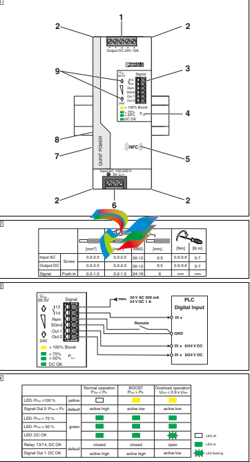
1. Denominação dos elementos ()
1. Terminal de conexão tensão de saída: Output DC +/-
2. Recepção para cinta de cabos
3. Terminais de conexão para sinalização
4. Indicadores de status e diagnóstico
5. Interface NFC (Near Field Communication). Configura-se
este aparelho em estado desenergizado ou em modo de
repouso (SLEEP MODE).
6. Tensão de entrada do terminal de conexão: Input L/N/
7. Protetor de surto por descarga de gás (lado esquerdo do
invólucro) contra sobretensão. Ao verificar o isolamento
(>0,8 kV AC ou 1,1 kV DC), desconectar o protetor de surto
por descarga de gás (remover o parafuso Philips)
8. Adaptador universal para trilho de fixação (parte traseira do
dispositivo)
9. Tecla da tensão de saída (-)/ (+)
2. Terminais de conexão e de sinalização ( - )
– 13/14: contato de comutação sem potencial
– Rem: entrada remoto < 1,5 k (SLEEP MODE)
– SGnd (Signal Ground): sinais do potencial de referência,
isolados galvanicamente da tensão de saída
– Out 1: DC OK (digital: 0/24 V DC)
– Out 2: POut < PN (digital: 0/24 V DC)
As características técnicas aqui apresentadas referem-se
a um aparelho entregue em padrão de fábrica. Aparelhos
com parâmetros personalizados para clientes podem
apresentar características técnicas diferentes destas.
Antes de colocação em funcionamento, ler as instruções
de montagem e detectar se há danificações no aparelho.
Outras informações encontram-se respectiva na ficha
técnica em phoenixcontact.net/products.
Avisos de segurança e alertas
O aparelho somente pode ser instalado, colocado em
funcionamento e operado por pessoal técnico qualificado.
Devem ser cumpridas as normas nacionais de segurança
e prevenção de acidentes.
ATENÇÃO: Perigo de queimaduras
Os dissipadores da fonte de corrente podem alcançar,
dependendo do nível de uso, temperaturas
UL 508 NOTA
Utilizar cabo de cobre com uma temperatura de operação de
75 °C (temperatura ambiente 55 °C) e
90 °C (temperatura ambiente 75 °C).
UL 60950 NOTA
Utilizar terminais tubulares para cabos flexíveis.
GL NOTA
Fechar áreas de bornes não utilizadas
ITALIANO
Alimentazione switching
– Attenzione: pericolo di morte a causa di scosse elettriche.
Non lavorare mai in presenza di tensione.
– L'alimentatore è omologato per la connessione a reti elettriche
TN, TT e IT (collegamento a stella) con tensione tra le fasi di
max. 240 V AC.
– L’alimentazione di corrente va collegata al di fuori senza
tensione, secondo le disposizioni della norma EN 60950-1
(per es. mediante la protezione di linea sul lato primario).
– L'alimentatore è un apparecchio da incorporare. Il grado di
protezione IP20 dell'apparecchio è previsto per un ambiente
pulito e asciutto.
– Montare l'alimentatore in posizione di montaggio normale.
Posizione inferiore dei morsetti di connessione L/N/.
– Collegare a terra il morsetto per dispositivo conduttore di
protezione .
– Prevedere dimensioni e protezione sufficienti per il cablaggio
primario e secondario.
– I parametri di connessione, ad esempio la lunghezza del tratto
da spelare necessaria per il cablaggio con e senza capocorda
montato, sono riportati nella tabella corrispondente.
– Dopo l'installazione coprire il vano di connessione in modo da
evitare contatti delle parti sotto tensione (ad es. montaggio nel
quadro elettrico).
– L'alimentatore non richiede manutenzione. Eventuali
interventi di riparazione possono essere eseguiti soltanto dal
produttore. L'apertura della custodia comporta il decadere
della garanzia.
– L'uso non conforme comporta il decadimento della protezione
dei dispositivi.
1. Denominazione degli elementi ()
1. Morsetto di connessione tensione di uscita: Output DC +/-
2. Connessione per fascette fermacavi
3. Morsetti di connessione segnalazione
4. Segnalazioni di stato e di diagnostica
5. Interfaccia NFC (Near Field Communication). Il dispositivo
viene configurato in assenza di tensione o in SLEEP MODE.
6. Morsetto di connessione tensione d'ingresso: input L/N/
7. Scaricatore a gas (lato sinistro della custodia) per protezione
contro le sovratensioni. Per la verifica dell'isolamento
(>0,8 kV AC o 1,1 kV DC), scollegare lo scaricatore a gas
(rimuovere la vite a croce).
8. Adattatore universale per il fissaggio su guida (lato posteriore
del dispositivo)
9. Comando tensione di uscita (-)/ (+)
2. Morsetti di connessione e di segnale ( - )
– 13/14: contatto di commutazione a potenziale zero
– Rem: ingresso Remote <1,5 k (SLEEP MODE)
– SGnd (Signal Ground): potenziale di riferimento segnali, con
separazione galvanica dalla tensione di uscita
– Out 1: DC OK (digitale: 0/24 V DC)
– Out 2: POut < PN (digitale: 0/24 V DC)
Le caratteristiche tecniche riportate si riferiscono alla versione
standard del dispositivo fornita dalla fabbrica. I dispositivi
parametrizzati in funzione di esigenze specifiche del cliente
possono presentare caratteristiche tecniche differenti.
Prima della messa in funzione, leggere le istruzioni di
installazione e verificare che il dispositivo non presenti danni.
Ulteriori informazioni sono disponibili nella scheda tecnica
alla pagina phoenixcontact.net/products.
Avvertenze sulla sicurezza e sui pericoli
L'installazione, la messa in funzione e l'uso dello
strumento si devono affidare esclusivamente a tecnici
qualificati. Rispettare le norme di sicurezza e
antinfortunistiche nazionali.
AVVERTENZA: Pericolo di ustioni
Gli elementi di raffreddamento dell'alimentatore possono
accettare temperature >65 °C a seconda del carico
UL 508 NOTA:
Utilizzare cavi di rame con una temperatura di esercizio
75 °C (temperatura ambiente 55 °C) e
90 °C (temperatura ambiente 75 °C).
UL 60950 NOTA:
Utilizzare capocorda per cavi flessibili.
GL NOTA:
Chiudere i vani morsetto non utilizzati.
FRANÇAIS
Alimentation à découpage primaire
– Attention : danger de mort par électrocution. Ne jamais
travailler sur un module sous tension.
– L'alimentation est homologuée pour le raccordement aux
circuits électriques triphasés TN, TT et IT (réseau en étoile) à
tension de conducteur externe maximum de 240 V AC.
– L'alimentation doit pouvoir être coupée depuis l'extérieur
conformément aux dispositions de la norme EN 60950-1 (par
exemple, via le disjoncteur de ligne côté primaire).
– L'alimentation est encastrable. L'indice de protection IP20 est
valable dans un environnement propre et sec.
– Monter l'alimentation à son emplacement normal. Les bornes
de raccordement L/N/ sont situées en bas.
– Raccorder le bloc de jonction d'appareil du conducteur de
protection à la terre.
– Dimensionner et protéger les câblages primaire et secondaire
correctement.
– Les paramètres de branchement tels la longueur à dénuder
du câblage avec et sans embout se trouvent dans le tableau
correspondant.
– Après installation, recouvrir la zone des bornes pour éviter
tout contact fortuit avec des pièces sous tension (par
exemple, montage en armoire).
– L'alimentation ne nécessite aucun entretien. Seul le
constructeur est autorisé à effectuer des réparations.
L'ouverture du boîtier provoque l'extinction de la garantie.
– Une utilisation non conforme supprime toute protection de
l'appareil.
1. Désignation des éléments ()
1. Tension de sortie à la borne de raccordement : Output DC +/-
2. Logement pour attache-câble
3. Bornes de raccordement signalisation
4. Voyants de diagnostic et d'état
5. Interface NFC (Near Field Communication). L'appareil est
configuré hors tension ou en mode de veille (SLEEP MODE).
6. Tension d'entrée à la borne de raccordement : entrée L/N/
7. Eclateur à gaz (côté gauche du boîtier) de protection
antisurtension. Lors du contrôle de l'isolation (>0,8 kV AC ou
1,1 kV DC), défaire le contact de l'éclateur à gaz (déposer la
vis cruciforme)
8. Adaptateur universel pour profilé (arrière de l'appareil)
9. Bouton tension de sortie (-)/ (+)
2. Bornes de raccordement et de signal ( - )
– 13/14 : contact de commutation indépendant du potentiel
– Rem : entrée à distance < 1,5 k (SLEEP MODE)
– SGnd (Signal Ground) : signaux potentiel de référence, isolés
galvaniquement de la tension de sortie
– Out 1 : DC OK (TOR : 0/24 V DC)
– Out 2 : POut < PN (tout-ou-rien : 0/24 V DC)
Les caractéristiques techniques indiquées correspondent
à l'état de l'appareil standard à la sortie d'usine. Les
appareils paramétrés selon les besoins du client peuvent
présenter des caractéristiques techniques différentes.
Avant la mise en service, lire les instructions d'installation
et vérifier si l'appareil présente des dommages.
Vous trouverez de plus amples informations dans la fiche
technique correspondante sur le site phoenixcontact.net/
products.
Consignes de sécurité et avertissements
L'appareil ne doit être installé, mis en service et utilisé que
par du personnel qualifié. Respecter la législation
nationale en vigueur en matière de sécurité et de
prévention des accidents.
AVERTISSEMENT : Risque de brûlure
Les dissipateurs de chaleur de l'alimentation en tension
peuvent prendre une température >65 °C, selon le niveau
d'utilisation
UL 508 REMARQUE :
Utiliser les câbles en cuivre à une température de service
75 °C (température ambiante 55 °C) et
90 °C (température ambiante 75 °C).
UL 60950 REMARQUE:
Utiliser des embouts pour câbles flexibles.
GL REMARQUE :
Obturer les espaces de raccordement inutilisés.
ENGLISH
Primary-switched power supply unit
– Caution: Risk of electric shock. Never carry out work when
voltage is present.
– The power supply is approved for the connection to TN, TT
and IT power grids (star networks) with a maximum phase-tophase voltage of 240 V AC
– The device must be switched off outside the power supply in
accordance with the regulations of EN 60950-1 (e.g., by
means of line protection on the primary side).
– The power supply is a built-in device. The protection class
IP20 of the device is meant to be applied in a clean and dry
environment.
– Mount the power supply unit in the standard installation
position. Position of the L/N/ connection terminal blocks at
bottom.
– Connect the protective conductor device terminal block
with ground.
– Ensure that the primary-side wiring and secondary-side wiring
are the correct size and have sufficient fuse protection.
– You can find the connection parameters, such as the
necessary stripping length for the wiring with and without
ferrule, in the associated table.
– Cover termination area after installation in order to avoid
accidental contact with live parts (e. g., installation in control
cabinet).
– The power supply is maintenance-free. Repairs may only be
carried out by the manufacturer. The warranty no longer
applies if the housing is opened.
– Improper use invalidates the device protection.
1. Designation of the elements ()
1. Connection terminal block output voltage: Output DC +/-
2. Accommodation for cable binders
3. Connection terminal block signaling
4. Status and diagnostics indicators
5. NFC interface (Near Field Communication). The device is
configured when it is disconnected from voltage or in SLEEP
MODE.
6. Connection terminal block input voltage: input L/N/
7. Gas-filled surge arrester (left side of housing) for surge
protection. Disconnect gas-filled surge arrester (remove
Phillips head screw) during dielectric test (>0.8 kV AC or
1.1 kV DC)
8. Universal DIN rail adapter (rear of housing)
9. Button output voltage (-)/ (+)
2. Connection and signal terminal blocks ( - )
– 13/14: floating switch contact
– Rem: remote input <1.5 k (SLEEP MODE)
– SGnd (Signal Ground): reference potential signals,
electrically isolated from output voltage
– Out 1: DC OK (digital: 0/24 V DC)
– Out 2: POut < PN (digital: 0/24 V DC)
The technical characteristics indicated relate to the factory
setting of the standard device. Devices with customerspecific parameterizations may have different technical
characteristics.
Prior to startup, read the installations notes and check the
device for damage.
For additional information, please refer to the
corresponding data sheet at phoenixcontact.net/products.
Safety and warning instructions
Only professionals may install, start up, and operate the
device. Observe the national safety and accident
prevention regulations.
WARNING: Risk of burns
The heatsinks of the power supply can reach temperatures
>65 °C, depending on the load
UL 508 NOTE:
Use copper cables for operating temperatures of
75 °C (ambient temperature 55 °C)
90 °C (ambient temperature 75 °C).
UL 60950 NOTE:
Use ferrules for flexible cables.
GL NOTE:
Tighten screws on all unused terminals.
DEUTSCH
Primär getaktete Stromversorgung
– Vorsicht: Lebensgefahr durch Stromschlag. Niemals bei
anliegender Spannung arbeiten.
– Die Stromversorgung ist für den Anschluss an TN-, TT- und
IT-Stromnetze (Sternnetze) mit einer Außenleiterspannung
von maximal 240 V AC zugelassen
– Stromversorgung muss nach den Bestimmungen der
EN 60950-1 von außerhalb spannungslos zu schalten sein
(z. B. durch den primärseitigen Leitungsschutz).
– Die Stromversorgung ist ein Einbaugerät. Die Schutzart IP20
des Geräts ist für eine saubere und trockene Umgebung
vorgesehen.
– Stromversorgung in Normaleinbaulage montieren. Lage der
Anschlussklemmen L/N/ unten.
– Schutzleiter-Geräteklemme mit Erde verbinden.
– Primär- und sekundärseitige Verdrahtung ausreichend
dimensionieren und absichern.
– Die Anschlussparameter, wie z. B. erforderliche
Abisolierlänge für die Verdrahtung mit und ohne
Aderendhülse entnehmen Sie bitte der zugehörigen Tabelle.
– Nach der Installation den Klemmenbereich abdecken, um
unzulässiges Berühren spannungsführender Teile zu
vermeiden (z. B. Einbau im Schaltschrank).
– Die Stromversorgung ist wartungsfrei. Reparaturen sind nur
durch den Hersteller durchführbar. Bei Öffnen des Gehäuses
erlischt die Garantie.
– Durch unsachgemäßen Gebrauch erlischt der Geräteschutz.
1. Bezeichnung der Elemente ()
1. Anschlussklemme Ausgangsspannung: Output DC +/-
2. Aufnahme für Kabelbinder
3. Anschlussklemmen Signalisierung
4. Status- und Diagnoseanzeigen
5. NFC-Schnittstelle (Near Field Communication). Das Gerät
wird spannungsfrei oder im SLEEP MODE konfiguriert.
6. Anschlussklemme Eingangsspannung: Input L/N/
7. Gasableiter (linke Gehäuseseite) für Überspannungsschutz.
Bei Isolationsprüfung (>0,8 kV AC oder 1,1 kV DC)
Gasableiter dekontaktieren (Kreuzschraube entfernen)
8. Universal-Tragschienenadapter (Geräterückseite)
9. Taster Ausgangsspannung (-)/ (+)
2. Anschluss- und Signalklemmen ( - )
– 13/14: potenzialfreier Schaltkontakt
– Rem: Remote-Eingang <1,5 k (SLEEP MODE)
– SGnd (Signal Ground): Bezugspotenzial Signale, galvanisch
getrennt von der Ausgangsspannung
– Out 1: DC OK (digital: 0/24 V DC)
– Out 2: POut < PN (digital: 0/24 V DC)
Die angegebenen technischen Merkmale beziehen sich
auf die werkseitige Auslieferung des Standardgeräts.
Kundenspezifisch parametrierte Geräte können
abweichende technische Merkmale aufweisen.
Vor Inbetriebnahme die Einbauanweisung lesen und das
Gerät auf Beschädigung prüfen.
Weitere Informationen finden Sie im zugehörigen
Datenblatt unter phoenixcontact.net/products.
Sicherheits- und Warnhinweise
Nur qualifiziertes Fachpersonal darf das Gerät installieren,
in Betrieb nehmen und bedienen. Nationale Sicherheitsund Unfallverhütungsvorschriften sind einzuhalten.
WARNUNG: Verbrennungsgefahr
Die Kühlkörper der Stromversorgung können je nach
Auslastung Temperaturen >65 °C annehmen.
UL 508 HINWEIS:
Kupferkabel verwenden mit einer Betriebstemperatur
75 °C (Umgebungstemperatur 55 °C) und
90 °C (Umgebungstemperatur 75 °C).
UL 60950 HINWEIS:
Aderendhülsen für flexible Kabel verwenden.
GL HINWEIS:
Ungenutzte Klemmräume schließen.
-
 HIRSCHMANN MSM20-M2M2M2M2SY9HH9E Ethernet media modul
 -
 HIRSCHMANN SPIDER-PL-20-05T1999999TWVHHHH Industrial Ethernet Rail Switch
 -
 Hirschmann SPIDER-PL-20-07T1M2M299TWVHHHH Industrial ETHERNET Rail Switch
 -
.png) Hirschmann (Belden) RS20-1600M2M2SDAEHC09.1.00 DIN-rail managed industrial Fast Ethernet switch
Hirschmann (Belden) RS20-1600M2M2SDAEHC09.1.00 DIN-rail managed industrial Fast Ethernet switch -
 Hirschmann (Belden) RS30-1602O6O6TDAPHC09.1.00 DIN-rail managed industrial Ethernet switch
 -
 Hirschmann (Belden) RS30-2402O6T1SDAPHH09.0.13 DIN-rail industrial Ethernet switch
 -
Hirschmann (Belden) SPIDER-PL-20-04T1S29999TY9HHHH Ethernet DIN-rail switch
-
 HIRSCHMANN RS20-1600T1T1SDAUHX Switch
 -
 HIRSCHMANN BRS42-0012OOOO-SPCZ99HHSES industrial switch
 -
 Hirschmann RS20-0800S2S2TDHPHH09.0.14 Fast Ethernet DIN rail switch.
 -
 HIRSCHMANN MM20-Z6Z6M2M2SAHH Hybrid Fast Ethernet Media Module
 -
 HIRSCHMANN MM20-Z6Z6T1T1SAHH hot-swappable hybrid Fast Ethernet Media Module
 -
 HIRSCHMANN MM20-P9P9T1T1SAHH Hybrid Fast Ethernet Media Module
 -
 HIRSCHMANN MM20-M4T1T1T1SAHH Hybrid Fast Ethernet Media Module
 -
 HIRSCHMANN MM20-M4M4T1T1SAHH Hybrid Fast Ethernet Media Module
 -
 HIRSCHMANN MM20-M2M2M2M2SZHH Ethernet media module
 -
HIRSCHMANN MM20-M2M2M2M2SAHH Ethernet media module
-
 HIRSCHMANN MM20-T1T1T1T1EBH 4-port Fast Ethernet Copper Cable Media Module
 -
HIRSCHMANN MM20-T1T1T1T1SAHH 4-port Fast Ethernet Copper Cable Media Module
-
HIRSCHMANN MM20-T1T1T1T1SAHH 4-port Fast Ethernet Copper Cable Media Module
-
 HIRSCHMANN MM20-Z6Z6EBH Hot-swappable fast Ethernet media module
 -
 HIRSCHMANN MM20-Z6Z6SAHH Ethernet media module
 -
HIRSCHMANN MM20-Z6Z6Z6Z6EBH Industrial Media Module
-
 MSM40-T1T1T1TZ9HH9E99.9.99 HIRSCHMANN Switch
 -
 HIRSCHMANN MS20-0800SAAEHC / MS20-0800SAAEHC0 8-port modular Layer 2 management Ethernet switch
 -
 Hirschmann RSPM20-4T14T1SZ9HHS9 Switch RSPM20-4T14T1SZ9HHS9
 -
 HIRSCHMANN RS20-1600M2M2SDAEHH09.1. RS20/30/40 Managed Switch configurator
 -
HIRSCHMANN RS20-1600M2M2SDAEHX09.0.00 Ethernet switch
-
 HIRSCHMANN BELDEN SPIDER-PL-20-07T1M2M299TY9HHHH / SPIDERPL2007T1M2M299TY9HHHH
 -
HIRSCHMANN MM3-1FXS2/3TX1 Switching Board Module
-
 HIRSCHMANN RSPE30-24044O7T99-ECCP999HHSE2A08.1.00 Industrial-grade fanless management-type Ethernet switch
 -
 HIRSCHMANN RS30-1602OOZZSDAEHC09.1.00 DIN-rail-mounted managed Layer 2 Ethernet switch
 -
 HIRSCHMANN MACH104-20TX-F Managed 24-port Full Gigabit 19" Switch
 -
 HIRSCHMANN Switch RS20-0800M4M4SDAE
 -
Hirschmann RS30-1602O6O6SDAEHH09.1. Management-type Ethernet switch
-
 Hirschmann RS30-1602OOZZSDAEHC09.0.10 Open rack-style Ethernet switch
 -
 HIRSCHMANN RSPE30-24044O7T99-SCCV999HHSI2SXX.X.XX High-Availability Seamless Redundancy
 -
HIRSCHMANN RSPE30-24044O7T99-SCCZ999HHSE2A DIN-rail Ethernet switch
-
HIRSCHMANN MM2-4TX1-EEC switch
-
HIRSCHMANN MSM40-T1T1T1T1TZ9HH9E99.9.99 Module
-
 HIRSCHMANN RS20 Rail Switch RS20-0400S4T1SDAEHC07.1.01
 -
 HIRSCHMANN M4-FAST8-SFP Fast Ethernet media module
 -
 HIRSCHMANN RS20-0400M2T1SDAP Managed Fast-Ethernet-Switch
 -
 HIRSCHMANN BELDEN SPIDER II 8TX/1FX EEC Industrial Ethernet Rail Switch
 -
HIRSCHMANN MM3-2FXS2/2TX1
-
 HIRSCHMANN RS2-4TX/1FX EEC Industrial Ethernet Rail Switch
 -
 RS30-0802O6O6SDAEHC09.0.10 HIRSCHMANN Switch
 -
 HIRSCHMANN m4-8TP-RJ45 Ethernet Media Module
 -
 HIRSCHMANN MSP30-24040SCZ9URHHE3A switch
 -
 Hirschmann rack MS30-1602SAAPHC
 -
 HIRSCHMANN RS2-FX/FX Industrial Switch Module
 -
Rs1txfx - Hirschmann - Rs1-Tx/Fx Rail Switch
-
RS20-0800S2S2SDAEHC09.1.00 HIRSCHMANN Commutator
-
 Hirschmann EAGLE20 TX/TX Industrial Security Router
 -
 Hirschmann SPIDER-SL-20-04T1S29999SY9HHHH Industrial Switch
 -
 HIRSCHMANN MAR1040-4C4C4C4C9999SMMHRHHXX.X. Gigabit Ethernet Switch configurator
 -
 Hirschmann MAR1040 Industrial Switch
 -
 HIRSCHMANN BELDEN RS30-1602O6O6SDAE
 -
Hirschmann RS20-1600M2M2SDAUHC Ethernet DIN rail switch
-
 HIRSCHMANN OCTOPUS 24M industrial switch
 -
 HIRSCHMANN RS20-1600T1T1SDAE Management-type Ethernet switch
 -
 HIRSCHMANN RS20-1600T1T1SDAUHH industrial switch
 -
HIRSCHMANN RS20-0800M2M2SDAPHC09.0.04 switch
-
 Hirschmann MR 8-03 24V DC Industrial Modular Bridge/Router
 -
 HIRSCHMANN RS20-0400M2T1SDAPHC08.0.01 Managed Switch
 -
 MACH1130 Hirschmann Industrial Switch
 -
 HIRSCHMANN 943824-002 SPIDER 5TX Industrial Ethernet Switch
 -
 HIRSCHMANN RS30-0802O6O6SDAEHC09.1.00 Managed Industrial Switch
 -
 HIRSCHMANN RS20-0400M2M2TDAEHC04.0.01 Industrial Switch
 -
 HIRSCHMANN BRS20-0600Z6Z6-STCZ99HHSES Industrial Switch
 -
 HIRSCHMANN MACH104-20TX-FR-L3P Industrial Ethernet Switch
 -
 HIRSCHMANN RS40-0009CCCCEDBPHH06.0.01 Industrial Switch
 -
 HIRSCHMANN RS2-3TX/2FX EEC Industrial Ethernet Switch
 -
 Hirschmann MACH 1020/1030 Fast/Gigabit Rack Mount Switches
 -
HIRSCHMANN RS20-0800M2M2SDAPHC09.0.14 Industrial Switch
-
 HIRSCHMANN RS20-1600T1T1SDAEHC09.0.04 Industrial Switch
 -
 HIRSCHMANN RSB20-0800T1T1EAABHH Industrial Switch
 -
 HIRSCHMANN MACH4002-48+4G-L3E Industrial Backbone Switch
 -
 HIRSCHMANN RS20-0400S2T1SDAE Industrial Managed Switch
 -
HIRSCHMANN RS20-0800S2T1SDAUHC Industrial Switch
-
 HIRSCHMANN RS20-2400S4S4SDAEHC09.0.14 industrial switch
 -
 HIRSCHMANN OS20-001200T5T5T5- TBBZ999HHNE3S 08.1.00 industrial switch
 -
HIRSCHMANN OS20-001200T5T5T5- TBBZ999HHNE3S 08.1.00 industrial switch
-
 HIRSCHMANN RS40-0009CCCCSDAEHH09.0.14 switch
 -
 Hirschmann RS20-1600T1T1SDAUHC Management-type Ethernet Switch
 -
 Hirschmann M1-8SFP Switche
 -
Hirschmann Industrial Ethernet Ruggedized Switch MACH1000 Family
-
 Basler Electric, Solid State Protective Relay, BE1-60
 -
BASLER ELECTRIC SR4A-2B15B3A Static Voltage Regulator
-
.png) BASLER ELECTRIC EXCITER DIODE MONITOR EDM-200
BASLER ELECTRIC EXCITER DIODE MONITOR EDM-200 -
.png) BASLER ELECTRIC DECS125-15-B2C5 DIGITAL EXCITATION CONTROL SYSTEM V 2.0.9
BASLER ELECTRIC DECS125-15-B2C5 DIGITAL EXCITATION CONTROL SYSTEM V 2.0.9 -
 BASLER ELECTRIC BE1-851 OVERCURRENT PROTECTION RELAY MECHANISM
 -
 Basler Electric BE1-51A / BE151A
 -
 Basler Electric BE1-40Q Loss of Excitation Relay
 -
 Basler Electric BE1-87G Variable Percentage Differential Relay
 -
 Basler Electric BE1-11 Protection System I5A3M2P2N0EA00
 -
 BASLER ELECTRIC DECS-200-1C Digital Excitation Control System
 -
 Basler Electric / Kohler BE1-11g Generator Protection Relay G5A3M2J2N0E000
 -
BASLER ELECTRIC DECS125-15 DIGITAL EXCITATION CONTROL SYSTEM
-
 BASLER ELECTRIC BE1-951 OverCurrent Protecton System
 -
Basler Electric DECS-200-1L Digital Excitation Control System
-
 Basler Electric DGC-2020HD-5NS1DNSBA Digital Genset Controller -
 -
 BASLER ELECTRIC BE1-81T1EE1WA0N1F / BE181T1EE1WA0N1F
 -
 BASLER ELECTRIC BE1-25M1EA6PN5R1F / BE125M1EA6PN5R1F
 -
 BASLER ELECTRIC DECS-250-LN1SN1N DIGITAL EXCITATION CONTROL SYSTEM
 -
Basler Electric DECS-250-CN2CN 1N Digital Excitation Control System Unit
-
 BASLER ELECTRIC DECS-300-C0N0 DIGITAL EXCITATION CONTROL SYSTEM
 -
 BASLER ELECTRIC BE1-87T-A1E-A1J-D0S1F / BE187TA1EA1JD0S1F
 -
BASLER ELECTRIC BE1-11-G6D1M0J2P0E000 Protection System
-
 BASLER ELECTRIC BE1-GPS100-E4N1H1N GENERATOR PROTECTION SYSTEM
 -
 Jaquet Relay card (Auxiliary module) FTV 3090 377Z-03985
 -
 Jaquet Trip Chain Control card FTBU 3034 377Z-05030
 -
 Jaquet with input card -E04 FTFU 3024 -E04 377Z-05855
 -
 Jaquet with input card -E03 FTFU 3024- E03 377Z-03983
 -
 Jaquet FTFU 3024- E02 377Z-03982 with input card -E02
 -
 Jaquet FTFU 3024-E01 377Z-03981 with input card -E01
 -
 Hirschmann RS20-2400T1T1SDAE Industrial Managed Ethernet Switch
 -
 Hirschmann BELDEN EAGLE30-04022O6TT999SCCV9HSE3F
 -
 Hirschmann MM3-2FXS2/2TX MICE Media Module
 -
 Hirschmann RS20-1600M2M2SDAPHC08.0.05 Industrial Managed Switch
 -
 Hirschmann OZD Profi 12M G12-1300 PRO Fieldbus Repeater
 -
Hirschmann SPIDER 4TX/1FX-ST EEC Industrial Ethernet Switch
-
 Hirschmann MM2-2FXM3/2TX1 MICE Media Module
 -
 Hirschmann RS20-2400M2M2SDAPHC09.0.14 Industrial Switch
 -
 Hirschmann RS20-0400M2M2SDAEHC07.1.05 OpenRail Switch
 -
 Hirschmann OZD Profi 12M G12-EEC Fieldbus Repeater
 -
HIRSCHMANN MDA422-1/2-3.5c-23/46 sensor
-
Hirschmann RS30-2402T1T1SDAUHC Managed Industrial Switch


