
SHINKAWAVM-5 SERIES MONITOR MODEL VM-5K DUAL VIBRATION MONITOR INSTRUCTION MANUAL
7-2 BASIC KEY OPERATIONS
• (SET) key : Used to change the display mode of the LCD display and to
finalize input.
• (UP) key : Used to change parameters and increment set values.
• (DOWN) key : Used to change parameters and decrement set values.
• (RESET) key : Used to reset alarms set to self-holding.
• Alarm reset is not possible until the output condition has been released.
• An alarm lamp set flashing by the First-out Display function cannot be reset.
(Reset by shorting between the RES and COM terminals.)
• (CHECK) key : The CHECK key is used to adjust the gain while changing set
values with the UP and DOWN keys.
For example, if the CHECK key is pressed while the value 0.1
appears on the MEAS 2 LED display, a value corresponding to the
measurement range × 0.1 can be set.
• Each operation of the CHECK key will multiply the multiplier by 10.
: When the CHECK key is pressed during normal monitoring, the
monitor will go through self-diagnosis in the following sequence :
(1) LCD, LED display test (all lamps light)
(2) Self-diagnosis
(3) Display of diagnosis result (Normal) (Abnormal)
• The diagnosis result for CH1 is indicated on the MEAS 1 display and that for CH2 on
the MEAS 2 display.
• If an abnormality is found as a result of self-diagnosis, the error content is displayed
after approx. 3 seconds.
• In case of more than one abnormality, error contents are displayed at 3-second
intervals.
Error content display
Check items Display
CH1 OK (input abnormal) alarm HIGH
CH2 OK (input abnormal) alarm HIGH
CH1 OK(input abnormal) alarm LOW
CH2 OK(input abnormal) alarm LOW
CH1 A/D input 5V side over
CH2 A/D input 5V side over
CH1 A/D input 0V side over
CH2 A/D input 0V side over
For safe operation.....
Thank you for using our VM-5 Series Monitor. SHINKAWA Sensor Technology applies strict quality control
and inspections to ensure the high reliability of its products.
This instruction manual contains descriptive information, specifications, and operating, setting, and adjusting
procedures.
Please study the contents of this manual and related manuals thoroughly before installing or operating the
equipment, and keep it handy for future reference.
"Safety Conventions"
Please thoroughly study the following section entitled "Safety Conventions" before operating the
equipment.
The safety symbols explained in this section are placed outside the left margin next to the text to which they
apply.
This unit is designed for use by specialists or persons thoroughly familiar with the field.
Make sure that the end user receives the Instruction Manual delivered with this unit.
Before use.....
When the unit is received, inspect it for damage suffered in transport and check
whether it is the item you ordered. In the unlikely event that it was damaged in transport
or does not function according to specifications, please contact the SHINKAWA Office
or dealer nearest you.
Store the unit under the ambient conditions given in the specification.
Avoid places where it is exposed to high humidity or corrosive gases.
Make it a rule to follow the instructions given in this manual.
This manual contains important information designed to prevent personal injury and property damage, and
ensure safe operation of the equipment.
Familiarize yourself with the signs and symbols explained below before proceeding to read the manual, and
observe the instructions given.
■ Explanation of signs
Symbols Explanation
WARNING Indicates a potentially hazardous situation which, if not avoided, could result in death
or serious injury.
CAUTION Indicates a potentially hazardous situation which, if not avoided, may result in minor
or moderate injury. It may also be used to permit for property-damage-only accidents.
◊ "Serious injury" refers to such injuries as loss of eyesight, injuries, burns (due to heat or cold), electric
shock, fractures, and poisoning, that have permanent aftereffects and require hospitalization or long-term
outpatient treatment.
◊ "Moderate or minor injury" refers to such injuries as burns and electric shock that do not require
hospitalization or long-term outpatient treatment. "Property-damage-only accidents" refers to
consequential damage related to destruction of property and damage to the equipment.
■ Explanation of symbols
Symbols Explanation
Indicates a prohibited action.
Details are given in the text next to the symbol.
Indicates a mandatory action.
Details are given in the text next to the symbol.
To ensure safe use of this equipment, strictly observe the safety precautions provided in this manual, as well
as installation methods and methods of use stipulated by laws and regulations. SHINKAWA Sensor
Technology will not be liable for damage, etc. due to methods of use contravening to the instructions provided
here.
■ Safe use
WARNING
Make sure to ground.
May cause electric shock or malfunction.
Make sure to turn the power off before any wiring work.
Will cause electric shock.
CAUTION
Connect the input signal within the voltage range described in the
specification to the input terminals.
Will cause damage and malfunction of the instrument.
Install the monitor unit and its relay module unit in the same location in the
instrument rack.
Will cause damage to the instrument and malfunction of the turbine monitoring system.
A printed circuit board and electronic products may receive damage with
the static electricity of a human body.
Touch the metal part once and discharge your static electricity before
dealing with it.
Will cause damage and malfunction of the instrument.
Do not touch parts and soldered surfaces of the monitor unit.
Will cause damage and malfunction of the instrument.
The monitor unit is a precision instrument.
Take care not to expose it to excessive shock or vibration.
Do not change the parameter settings during operation.
May cause unexpected alarm output.
Do not pull out the face plate during operation.
Will cause damage to the instrument and malfunction of the turbine monitoring system.
Do not measure insulation resistance and dielectric strength other than
those at places specified.
Will cause damage to the instrument.
Do not remodel this monitor unit without permission.
Otherwise the guarantee can not be made.
■ EMC(Electro-magnetic compatibility)
The EMC of each VM-5 Series monitor is evaluated by various noise tests.
However, its characteristics may vary with on environmental conditions such as the magnitude of noise,
ambient temperature, humidity and the arrangement of equipment.
For the above reason, when operating the monitor, please observe the following CAUTION.
CAUTION
The monitor unit should be operated by specialists or personnel who have
knowledge of it.
When a shielded cable is used, the length of the unshielded cable section
should be less than 100mm (3.937in REF.).
For each relay used near this monitor unit, devices related to this monitor
unit or signal cables connecting the monitor unit and these devices, install
a surge killer.
Firmly tighten each screw used for mounting each unit. In additional,
always close the face plate for the monitor unit, then fix it with knurled
screws.
In order to prevent the system from its malfunction when the monitor unit
fails, provide the systematic interlock function.
Do not wire input signal cables in parallel with control and power cables.
It is recommended that separated wire ducts be used for these cables.
Do not use any radio equipment near the monitor unit.
■ Noise filter
Noise transmitted through in each cable may be rejected to some extent by inserting a ferrite core in the cable
(note 1).
If the cable passes through noisy surroundings, it is recommended that such a noise prevention device is used.
GENERAL INFORMATION
OVERVIEW
This is a highly reliable dual channel vibration monitor which monitors the shaft vibration of
rotating machinery.
Both a 10-slot rack mounting type and a single-unit independent type with a built-in power supply
are available so that it can respond flexibly to any system design from medium and small scale
rotating machinery to TSI. The monitor accepts signals detected by a transducer and displays them
on LCD.
It is also possible to set ALERT and DANGER alarm levels independently to detect machine
failures early on and inform the operator of these failures. It has a built-in self-diagnostic function
to inform the operator of input transducer failures, thereby preventing rotating machinery from
false shutdowns.
FEATURES
• Conforms to API St’d 670
• The monitor is available as a single unit independent type or a rack mounting type.
• Has a self-diagnostic function.
• Allows the operator to change each setting even in the field.
• Important information such as measured value, alarm set value and gap voltage is normally
displayed.
• Can isolate recorder output (option).
• LED display / contact output (DANGER / ALERT alarm).
• LED display / contact output (Input abnormal alarm).
• For alarm output wiring proceed as described in the instruction manuals for the
VM-5G Single Unit Instrument Rack and VM-5Y Relay Module Unit used in
combination with this monitor unit.
• If megger test is made on the signal cable between transducer and monitor,
disconnect the cable from transducer and monitor.
Be sure to discharge the charged electric load before connecting the cable to the
transducer and monitor.
If this caution is not adhered to, the transducer and monitor could be damaged.
FIRSTOUT DISPLAY
• Installation in VM-5H3, 5W1 Instrument Rack
Causes the alarm lamp of the channel that first output alarm to flash.
• Installation in VM-5G Single Unit Instrument Rack
Causes the lamp of the alarm first output to flash.
For details refer to 7. PARAMETER SETTING on page 19.
• An alarm lamp set flashing by the First-out Display function cannot be reset by
pressing the RES (RESET) key.
Reset by shorting between the RES and COM terminals.
• It is necessary to keep short circuit of the terminals for more than one (1) second to
operate these functions.
5-9 SEQUENCE FUNCTION
To prevent alarm output due to excessive vibration generated during starting and stopping of the
machine, this function expands the DANGER alarm and ALERT alarm set ranges by shorting
between the SEQ. and COM terminals.
• The machine is not protected if the alarm set value exceeds 110% of the monitor
range due to operation of the sequence circuit.
• It is necessary to keep short circuit of the terminals for more than one (1) second to
operate these functions.
5-10 BYPASS FUNCTION
Used to disable alarm output while setting the alarm parameters, or during maintenance/inspection
work. The alarm BYPASS lamp flashes or lights during this operation. Set by turning the BYPASS
switch to ON.
• While BYPASS FUNCTION is in operation, the machine is not protected.
5-10-1 DANGER BYPASS
Cuts off DANGER alarm. While cut off, the DANGER alarm and BYPASS lamps are flashing.
This function is activated by means of the DANGER BYPASS switch. For details refer to 7.
PARAMETER SETTING on page 19.
• If mounted in the VM-5H3 or VM-5W1 Instrument Rack, all units in the instrument
rack can be set collectively to DANGER BYPASS.
For details refer to VM-5H3 or VM-5W1 Instrument Rack instruction manual.
5-10-2 CH1 BYPASS
DANGER alarm, ALERT alarm, OK alarm, display and recorder output of CH1 are cut off.
While cut off, the OK lamp goes off and the BYPASS lamp lights.
This function can be activated by means of the CH1 BYPASS switch.
For details refer to 7. PARAMETER SETTING on page 19.
5-10-3 CH2 BYPASS
DANGER alarm, ALERT alarm, OK alarm, display and recorder output of CH2 are cut off.
While cut off, the OK lamp goes off and the BYPASS lamp lights.
This function can be activated by means of the CH2 BYPASS switch.
For details refer to 7. PARAMETER SETTING on page 19.
5-11 POWER ON TIMER MODE
Operates for approx. 5sec. after the power is turned on. (for approx. 25 sec. in case of pk-pk
detection). In this mode, all alarm functions are disabled and the BYPASS and OK lamps flash.
5-12 ALARM RELAY MODE
Each alarm contact can be set to either normally de-energized or normally energized.
Alarm contact operation
Monitor power Monitor power ON
OFF Normal state Alarm state
NO contact NORMALLY DE-ENERGIZED OPEN OPEN CLOSE
NO contact NORMALLY ENERGIZED OPEN CLOSE OPEN
NC contact NORMALLY DE-ENERGIZED CLOSE CLOSE OPEN
NC contact NORMALLY ENERGIZED CLOSE OPEN CLOSE
For details refer to 7. PARAMETER SETTING on page 19.
5-13 ALARM RESET MODE
The automatic reset of all alarm output and alarm lamps can be set when the measured value or
input signal return to normal. In addition to above, the self-holding function can be also set for
each alarm output that holds the alarm condition until reset by setting RES key (inside of the front
panel) or by shorting between RES and COM terminal.
• Alarm reset is not possible until the output condition has been released.
• It is necessary to keep short circuit of the terminals for more than one (1) second to
operate these functions.
For details refer to 7. PARAMETER SETTING on page 19.
5-14 MONITOR OUTPUT
For vibration analysis, the vibration waveform signal is output from the BNC connector on the
monitor front panel and buffer output terminal on the rear panel (VM-5G Single Unit Instrument
Rack, VM-5Y Relay Module Unit) via a buffer amplifier.
5-15 RECORDER OUTPUT
An analog signal proportional to the vibration value is output from the terminal block.
5-16 SELF-DIAGNOSTIC FUNCTION
Any failures in the input system, such as sensor short-circuit or imperfect connections, are detected,
then an OK alarm is contact-output and (simultaneously), the OK lamp flashes.
5-17 POWER SEQUENCE
If mounted in the VM-5G Single Unit Instrument Rack, the secondary power supply can be cut off
by shorting between the P-S (POWER SEQUENCE) and COM terminals.
• This function can be used for pulling out or pulling in the monitor unit at the
emergency time. However, do not use for long time shorting of more than one (1)
minute or turning on and off repeatedly.
Also, the parallel connection for the two (2) or more monitors should not be allowed.
5-18 TIMED OK CHANNEL DEFEAT
When on setting, when OK alarm is output, DANGER alarm, ALERT alarm, display, and recorder
output are disabled. DANGER ALERT, display and recorder output are not disabled, in case of
excessive signal input from sensor.
For details refer to 7. PARAMETER SETTING on page 19.
5-19 SUPPRESSION FUNCTION
This function can suppress the measurement around zero measurement point of the monitor by the
effect of the piping vibration or electric noise, etc. during the machine stopping.
The suppression can be set at 0.0 to 10.0 % (0.1% step) of the monitor range.
ex.) If the suppression is set at 2.0%, monitor measurement less than 2.0% shall be output as 0.0%
2 DESCRIPTION OF PARTS 1 LCD display This LCD display serves for display of measured values, alarm set values, sensor set gap voltage value and other set values. 2 DANGER alarm lamp Lit when DANGER alarm is output. 3 ALERT alarm lamp Lit when ALERT alarm is output. 4 OK lamp Flashes (steady light in normal condition) when OK (input abnormal) alarm is output. 5 BYPASS lamp Flashes during DANGER bypass and lights during CHANNEL bypass. 6 Monitor output connector This is a BNC output connector for connection of an oscilloscope to observe the waveform, or for output to other devices such as an analyzer. The input signals from the transducers are output through a buffer amplifier. • Make sure to insulate the monitor output against earth. If not insulated, a 2-point earth system results, which may cause noise interference. 7 Name plate 8 Tag, Ser. No. plate The TAG NO. and SER.NO. are entered on this plate. 9 LCD board 10 Slide frame 11 Main board frame 12 Main board 13 DIN connector (64pin) Connector for connection to the VM-5G Single Unit Instrument Rack or VM-5H3 or VM-5W1 Instrument Rack.
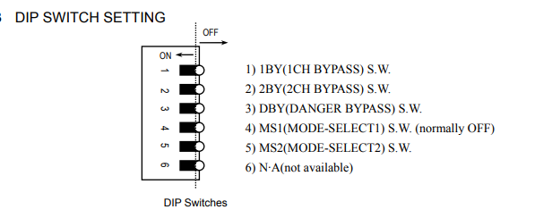
1) 1BY (CH1 BYPASS) Switch
"ON" To select CH1 BYPASS function.
"OFF" Normal monitoring
2) 2BY (CH2 BYPASS) Switch
"ON" To select CH2 BYPASS function.
"OFF" Normal monitoring
3) DBY (DANGER BYPASS) Switch
"ON" To select DANGER BYPASS function.
"OFF" Normal monitoring
4) MS1 (MODE-SELECT1) Switch (normally OFF)
• Set normally to “OFF”. Parameter setting mode is disabled.
5) MS2 (MODE-SELECT2) Switch
“ON”
For setting the alarm reset mode, alarm delay time, alarm relay mode, first-out display,
and timed OK channel defeat.
Also enables setting the address when used in combination with the VM-5H3 or 5W1
Instrument Rack and VM-5P1,2 Communication/Phase Marker Unit or VM-53 Dual
Communication Unit. To PARAMETER SETTING 1.
“OFF”
For changing the set values for DANGER alarm and ALERT alarm, and GAP ALARM,
and adjusting measured value and recorder output zero span.
To PARAMETER SETTING 2.
-
 HIRSCHMANN MSM20-M2M2M2M2SY9HH9E Ethernet media modul
 -
 HIRSCHMANN SPIDER-PL-20-05T1999999TWVHHHH Industrial Ethernet Rail Switch
 -
 Hirschmann SPIDER-PL-20-07T1M2M299TWVHHHH Industrial ETHERNET Rail Switch
 -
.png) Hirschmann (Belden) RS20-1600M2M2SDAEHC09.1.00 DIN-rail managed industrial Fast Ethernet switch
Hirschmann (Belden) RS20-1600M2M2SDAEHC09.1.00 DIN-rail managed industrial Fast Ethernet switch -
 Hirschmann (Belden) RS30-1602O6O6TDAPHC09.1.00 DIN-rail managed industrial Ethernet switch
 -
 Hirschmann (Belden) RS30-2402O6T1SDAPHH09.0.13 DIN-rail industrial Ethernet switch
 -
Hirschmann (Belden) SPIDER-PL-20-04T1S29999TY9HHHH Ethernet DIN-rail switch
-
 HIRSCHMANN RS20-1600T1T1SDAUHX Switch
 -
 HIRSCHMANN BRS42-0012OOOO-SPCZ99HHSES industrial switch
 -
 Hirschmann RS20-0800S2S2TDHPHH09.0.14 Fast Ethernet DIN rail switch.
 -
 HIRSCHMANN MM20-Z6Z6M2M2SAHH Hybrid Fast Ethernet Media Module
 -
 HIRSCHMANN MM20-Z6Z6T1T1SAHH hot-swappable hybrid Fast Ethernet Media Module
 -
 HIRSCHMANN MM20-P9P9T1T1SAHH Hybrid Fast Ethernet Media Module
 -
 HIRSCHMANN MM20-M4T1T1T1SAHH Hybrid Fast Ethernet Media Module
 -
 HIRSCHMANN MM20-M4M4T1T1SAHH Hybrid Fast Ethernet Media Module
 -
 HIRSCHMANN MM20-M2M2M2M2SZHH Ethernet media module
 -
HIRSCHMANN MM20-M2M2M2M2SAHH Ethernet media module
-
 HIRSCHMANN MM20-T1T1T1T1EBH 4-port Fast Ethernet Copper Cable Media Module
 -
HIRSCHMANN MM20-T1T1T1T1SAHH 4-port Fast Ethernet Copper Cable Media Module
-
HIRSCHMANN MM20-T1T1T1T1SAHH 4-port Fast Ethernet Copper Cable Media Module
-
 HIRSCHMANN MM20-Z6Z6EBH Hot-swappable fast Ethernet media module
 -
 HIRSCHMANN MM20-Z6Z6SAHH Ethernet media module
 -
HIRSCHMANN MM20-Z6Z6Z6Z6EBH Industrial Media Module
-
 MSM40-T1T1T1TZ9HH9E99.9.99 HIRSCHMANN Switch
 -
 HIRSCHMANN MS20-0800SAAEHC / MS20-0800SAAEHC0 8-port modular Layer 2 management Ethernet switch
 -
 Hirschmann RSPM20-4T14T1SZ9HHS9 Switch RSPM20-4T14T1SZ9HHS9
 -
 HIRSCHMANN RS20-1600M2M2SDAEHH09.1. RS20/30/40 Managed Switch configurator
 -
HIRSCHMANN RS20-1600M2M2SDAEHX09.0.00 Ethernet switch
-
 HIRSCHMANN BELDEN SPIDER-PL-20-07T1M2M299TY9HHHH / SPIDERPL2007T1M2M299TY9HHHH
 -
HIRSCHMANN MM3-1FXS2/3TX1 Switching Board Module
-
 HIRSCHMANN RSPE30-24044O7T99-ECCP999HHSE2A08.1.00 Industrial-grade fanless management-type Ethernet switch
 -
 HIRSCHMANN RS30-1602OOZZSDAEHC09.1.00 DIN-rail-mounted managed Layer 2 Ethernet switch
 -
 HIRSCHMANN MACH104-20TX-F Managed 24-port Full Gigabit 19" Switch
 -
 HIRSCHMANN Switch RS20-0800M4M4SDAE
 -
Hirschmann RS30-1602O6O6SDAEHH09.1. Management-type Ethernet switch
-
 Hirschmann RS30-1602OOZZSDAEHC09.0.10 Open rack-style Ethernet switch
 -
 HIRSCHMANN RSPE30-24044O7T99-SCCV999HHSI2SXX.X.XX High-Availability Seamless Redundancy
 -
HIRSCHMANN RSPE30-24044O7T99-SCCZ999HHSE2A DIN-rail Ethernet switch
-
HIRSCHMANN MM2-4TX1-EEC switch
-
HIRSCHMANN MSM40-T1T1T1T1TZ9HH9E99.9.99 Module
-
 HIRSCHMANN RS20 Rail Switch RS20-0400S4T1SDAEHC07.1.01
 -
 HIRSCHMANN M4-FAST8-SFP Fast Ethernet media module
 -
 HIRSCHMANN RS20-0400M2T1SDAP Managed Fast-Ethernet-Switch
 -
 HIRSCHMANN BELDEN SPIDER II 8TX/1FX EEC Industrial Ethernet Rail Switch
 -
HIRSCHMANN MM3-2FXS2/2TX1
-
 HIRSCHMANN RS2-4TX/1FX EEC Industrial Ethernet Rail Switch
 -
 RS30-0802O6O6SDAEHC09.0.10 HIRSCHMANN Switch
 -
 HIRSCHMANN m4-8TP-RJ45 Ethernet Media Module
 -
 HIRSCHMANN MSP30-24040SCZ9URHHE3A switch
 -
 Hirschmann rack MS30-1602SAAPHC
 -
 HIRSCHMANN RS2-FX/FX Industrial Switch Module
 -
Rs1txfx - Hirschmann - Rs1-Tx/Fx Rail Switch
-
RS20-0800S2S2SDAEHC09.1.00 HIRSCHMANN Commutator
-
 Hirschmann EAGLE20 TX/TX Industrial Security Router
 -
 Hirschmann SPIDER-SL-20-04T1S29999SY9HHHH Industrial Switch
 -
 HIRSCHMANN MAR1040-4C4C4C4C9999SMMHRHHXX.X. Gigabit Ethernet Switch configurator
 -
 Hirschmann MAR1040 Industrial Switch
 -
 HIRSCHMANN BELDEN RS30-1602O6O6SDAE
 -
Hirschmann RS20-1600M2M2SDAUHC Ethernet DIN rail switch
-
 HIRSCHMANN OCTOPUS 24M industrial switch
 -
 HIRSCHMANN RS20-1600T1T1SDAE Management-type Ethernet switch
 -
 HIRSCHMANN RS20-1600T1T1SDAUHH industrial switch
 -
HIRSCHMANN RS20-0800M2M2SDAPHC09.0.04 switch
-
 Hirschmann MR 8-03 24V DC Industrial Modular Bridge/Router
 -
 HIRSCHMANN RS20-0400M2T1SDAPHC08.0.01 Managed Switch
 -
 MACH1130 Hirschmann Industrial Switch
 -
 HIRSCHMANN 943824-002 SPIDER 5TX Industrial Ethernet Switch
 -
 HIRSCHMANN RS30-0802O6O6SDAEHC09.1.00 Managed Industrial Switch
 -
 HIRSCHMANN RS20-0400M2M2TDAEHC04.0.01 Industrial Switch
 -
 HIRSCHMANN BRS20-0600Z6Z6-STCZ99HHSES Industrial Switch
 -
 HIRSCHMANN MACH104-20TX-FR-L3P Industrial Ethernet Switch
 -
 HIRSCHMANN RS40-0009CCCCEDBPHH06.0.01 Industrial Switch
 -
 HIRSCHMANN RS2-3TX/2FX EEC Industrial Ethernet Switch
 -
 Hirschmann MACH 1020/1030 Fast/Gigabit Rack Mount Switches
 -
HIRSCHMANN RS20-0800M2M2SDAPHC09.0.14 Industrial Switch
-
 HIRSCHMANN RS20-1600T1T1SDAEHC09.0.04 Industrial Switch
 -
 HIRSCHMANN RSB20-0800T1T1EAABHH Industrial Switch
 -
 HIRSCHMANN MACH4002-48+4G-L3E Industrial Backbone Switch
 -
 HIRSCHMANN RS20-0400S2T1SDAE Industrial Managed Switch
 -
HIRSCHMANN RS20-0800S2T1SDAUHC Industrial Switch
-
 HIRSCHMANN RS20-2400S4S4SDAEHC09.0.14 industrial switch
 -
 HIRSCHMANN OS20-001200T5T5T5- TBBZ999HHNE3S 08.1.00 industrial switch
 -
HIRSCHMANN OS20-001200T5T5T5- TBBZ999HHNE3S 08.1.00 industrial switch
-
 HIRSCHMANN RS40-0009CCCCSDAEHH09.0.14 switch
 -
 Hirschmann RS20-1600T1T1SDAUHC Management-type Ethernet Switch
 -
 Hirschmann M1-8SFP Switche
 -
Hirschmann Industrial Ethernet Ruggedized Switch MACH1000 Family
-
 Basler Electric, Solid State Protective Relay, BE1-60
 -
BASLER ELECTRIC SR4A-2B15B3A Static Voltage Regulator
-
.png) BASLER ELECTRIC EXCITER DIODE MONITOR EDM-200
BASLER ELECTRIC EXCITER DIODE MONITOR EDM-200 -
.png) BASLER ELECTRIC DECS125-15-B2C5 DIGITAL EXCITATION CONTROL SYSTEM V 2.0.9
BASLER ELECTRIC DECS125-15-B2C5 DIGITAL EXCITATION CONTROL SYSTEM V 2.0.9 -
 BASLER ELECTRIC BE1-851 OVERCURRENT PROTECTION RELAY MECHANISM
 -
 Basler Electric BE1-51A / BE151A
 -
 Basler Electric BE1-40Q Loss of Excitation Relay
 -
 Basler Electric BE1-87G Variable Percentage Differential Relay
 -
 Basler Electric BE1-11 Protection System I5A3M2P2N0EA00
 -
 BASLER ELECTRIC DECS-200-1C Digital Excitation Control System
 -
 Basler Electric / Kohler BE1-11g Generator Protection Relay G5A3M2J2N0E000
 -
BASLER ELECTRIC DECS125-15 DIGITAL EXCITATION CONTROL SYSTEM
-
 BASLER ELECTRIC BE1-951 OverCurrent Protecton System
 -
Basler Electric DECS-200-1L Digital Excitation Control System
-
 Basler Electric DGC-2020HD-5NS1DNSBA Digital Genset Controller -
 -
 BASLER ELECTRIC BE1-81T1EE1WA0N1F / BE181T1EE1WA0N1F
 -
 BASLER ELECTRIC BE1-25M1EA6PN5R1F / BE125M1EA6PN5R1F
 -
 BASLER ELECTRIC DECS-250-LN1SN1N DIGITAL EXCITATION CONTROL SYSTEM
 -
Basler Electric DECS-250-CN2CN 1N Digital Excitation Control System Unit
-
 BASLER ELECTRIC DECS-300-C0N0 DIGITAL EXCITATION CONTROL SYSTEM
 -
 BASLER ELECTRIC BE1-87T-A1E-A1J-D0S1F / BE187TA1EA1JD0S1F
 -
BASLER ELECTRIC BE1-11-G6D1M0J2P0E000 Protection System
-
 BASLER ELECTRIC BE1-GPS100-E4N1H1N GENERATOR PROTECTION SYSTEM
 -
 Jaquet Relay card (Auxiliary module) FTV 3090 377Z-03985
 -
 Jaquet Trip Chain Control card FTBU 3034 377Z-05030
 -
 Jaquet with input card -E04 FTFU 3024 -E04 377Z-05855
 -
 Jaquet with input card -E03 FTFU 3024- E03 377Z-03983
 -
 Jaquet FTFU 3024- E02 377Z-03982 with input card -E02
 -
 Jaquet FTFU 3024-E01 377Z-03981 with input card -E01
 -
 Hirschmann RS20-2400T1T1SDAE Industrial Managed Ethernet Switch
 -
 Hirschmann BELDEN EAGLE30-04022O6TT999SCCV9HSE3F
 -
 Hirschmann MM3-2FXS2/2TX MICE Media Module
 -
 Hirschmann RS20-1600M2M2SDAPHC08.0.05 Industrial Managed Switch
 -
 Hirschmann OZD Profi 12M G12-1300 PRO Fieldbus Repeater
 -
Hirschmann SPIDER 4TX/1FX-ST EEC Industrial Ethernet Switch
-
 Hirschmann MM2-2FXM3/2TX1 MICE Media Module
 -
 Hirschmann RS20-2400M2M2SDAPHC09.0.14 Industrial Switch
 -
 Hirschmann RS20-0400M2M2SDAEHC07.1.05 OpenRail Switch
 -
 Hirschmann OZD Profi 12M G12-EEC Fieldbus Repeater
 -
HIRSCHMANN MDA422-1/2-3.5c-23/46 sensor
-
Hirschmann RS30-2402T1T1SDAUHC Managed Industrial Switch


