
alstom AMS42/84 5B Amplifier SystemAmplifier Technology at its Best.
5B Amplifier System
Amplifier Technology at its Best.
AMS42/84
5B Amplifier System
Amplifier Technology at its Best.

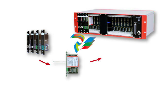
Compact or 19 Inch.
Get your amplifier technology wrapped up with
the AMS42/84. Available in a robust aluminum
housing as a mobile tabletop unit (AMS42) with
skid-proof, tip-up feet for 8 channels or as a
16-channel stationary version (AMS84) for 19''
rack systems.
Modular Concept.
Equip Individually. Be Flexible.
The AMS device is equipped with cassettes, on
which the required 5B measuring amplifiers are
mounted. The variety of available 5B modules
allows for the optimum adaptation of the
AMS42/84 to any special measuring task.
Choose Connector.
Mount 5B Amplifier. Done.
The available plug-in cassettes have different
connectors on the front panel. Depending on
the sensor or signal to be connected, the
suitable cassette can be chosen. The 5B
module only has to be fixed on the cassette
now and be integrated in the AMS system.
Clearly Safe.
Most of the 5B modules feature galvanic
isolation between the channels and from the
data acquisition and control system. This
perfectly protects the whole system against
high potentials and interferences.
Well Supplied.
The AMS42/84 is operated with 9-40V via an
external power supply.
Connection to the DAQ System.
The amplifier outputs are available at a D
Sub37 female connector. They are connected
to the input lines of a data acquisition system.
Combining the AMS42/84 with a measuring
card or DAQ system from bmcm makes a
powerful measurement system.
Accessories. Just Makes it Easier.
To individually equip the AMS devices, various
5B modules and plug-in cassettes as well as
other accessories (e.g. external power supply,
carrying handle, connection cable) are
provided.
Versions and Options.
Something for Everybody.
AMS42/84 versions with an integrated DAQ
system (USB, LAN) are also available. With the
8-channel extension AMS-EXT8. the number of
channels can optionally be increased to 16 in
the AMS42.
1 Installation
1.1 Assembly
a) Equip the AMS42/84 with the plug-in cassettes (see chapter 4.2) carrying the required 5B
modules.
b) Carefully push the cassette along the guide bars of the relevant slot until the 7-way pin
connector of the cassette and the pins of the 5B module are plugged into the corresponding
connectors on the AMS backplane.
c) If using the AMS42 with the option AMS-EXT8 (see chapter 4.4), the additional cassettes are
mounted on the back of the device.
d) For a tight installation, fix the front panel at both ends with screws to the housing. Bridge
unneeded slots by a blank panel (AMS-K-BLANK) to protect the device against outside
influences.
e) If the AMS84 is mounted to a 19'' rack system, the relevant input wiring should be prepared first
before attaching the device to the rack system with screws.
1.2 Software Installation and Start-up Procedure
a) Connect your PC data acquisition system to the 37-pin D-Sub female.
b) Attach an external power unit to the 3-pin DIN coupling for 9-40V power supply (use a supply
cable with a cross sectional area >1mm2) and turn on the AMS42/84 by pressing the switch to
"1" (ON) (see chapter 2.1 and 2.2).
c) Signals are attached at the specific connector of the respective AMS cassette panel.
• To change the cassettes, the power of the AMS device must be turned off!
• If the AMS system is operated standalone, additional grounding to enhance shielding is
recommended but not mandatory.
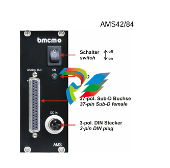
2 Connections / Assignments
All available connectors and operating elements of the
AMS42/84 are accessible on the right-hand side of the
device front.
2.1 Switch and LED
The AMS42/84 is turned on (press "1") and off (press "0")
with the switch.
The green LED "ON" indicates the operation of the device.
2.2 Power Supply "DC In"
The AMS device is supplied with power (9..40V) via the 3
pin DIN plug. A power supply unit ZU-PW40W (24V, 1.67A
DC) is optionally available.
2.3 Analog Channels
8 (AMS42) or 16 (AMS84) analog signals can be connected to the
amplifier inputs available at the respective connectors of the cassette
panels.
Their assignment is illustrated in the data sheet of the AMS-K cassettes.
To connect a PC data acquisition system, these analog outputs are led
out to the 37-pin D-Sub female.
Depending on the application, the shield of the analog input cables can be applied to ground or 0V. Be
sure to connect at one end of the cable only. Run the signal ground separately if possible. Lay input
cable separately if possible.
• The housing of the D-Sub37 female is connected to the AMS housing (and ground eventually).
• If the device features 16 channels (AMS84. AMS42 + AMS-EXT8), the ground of the first eight
channels is not electrically connected to the ground of the next eight channels.
3 AMS Backplane
The AMS-backplane provides 8 slots for 5B modules and the AMS-K plug-in cassettes (see chapter
4.2) carrying the 5B modules. Two backplanes are integrated in the AMS84.
If the optional add-on AMS-EXT8 (see chapter 4.4) is used, eight slots each are available on the front
and on the back of the AMS42.
3.1 Ground-to-Ground Resistance
Ideally, the output ground is not electrically connected with the power supply ground. If, however, a
connection to ground is necessary (e.g. to use the output switch in the 5B module), the 2-pin jumper
(see fig. above) must be closed.
In the case of electrically connected systems (e.g. PC), this jumper represents a high-resistance
bridge (1k ) and may generate a hum loop!
3.2 Module Pin Assignment
The pin assignment on the right shows the top view of the module
backplane (see chapter 3).
The pin assignment corresponds to the 5B modules of Analog
Devices®, BURR BROWN® etc. However, an additional 0EX pin has
been introduced, which is particularly suitable for ungrounded
shielding. This is a specific assignment of BMC Messsysteme
GmbH. The 0EX pin is not connected in modules of other
manufacturers.
3.3 Fuse
The fusing of the AMS backplane is effected on the backplane (see chapter 3) with one reversible
semi-conductor fuse. In case of overload, it turns off. To make the fuse work effectively again, first
remove the cause for overload before disconnecting the power supply of the AMS42/84.
3.4 Connection for AMS Cassettes
The cassettes are connected to the AMS backplane via 7-way pin connectors,
leading the input signals connected at the cassette panel to the backplane. The
assignment of the 7-way female connector on the board is illustrated in the figure on
the right-hand side.
4 Supplementary Products for AMS42/84
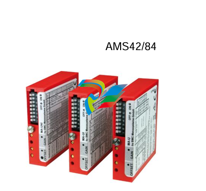
4.1 5B Modules (MA Line)
The 5B measuring amplifiers from bmcm allow for the professional
signal adjustment to a data acquisition system.
The amplifier output is 5V or 0..5V. Most of the modules are
electrically isolating and provide sensor supply.
The following 5B modules from bmcm are available:
4.2 Plug-in Cassettes (AMS-K Line)
The amplifier system can be individually equipped with 8
(AMS42-USB) or 16 (AMS84) plug-in cassettes.
Each cassette is equipped with the relevant 5B module and
suitable input connector.
The suitable input connector on the front panel guarantees for
the relevant connection to be available when exchanging the
cassette.
The following cassettes are available:
Product
Description
AMS-K-BIN5
cassette with panel and 5-pin Binder female connector (712 series)
AMS-K-BLANK blank panel
AMS-K-BNC
AMS-K-CO5
cassette with front panel and BNC female connector
cassette with front panel and 5-pin terminal connector
AMS-K-THK
cassette with front panel and thermocouple socket (type K)
4.3 AMS-HANDLE2. AMS-FOOT
For mobile use, the AMS42/84 can be equipped with two stable
metal handles at the housing frame (AMS-HANDLE2).
If the AMS84 is not installed in a 19'' rack, a set of tip-up feet
(AMS-FOOT) can optionally be ordered.
4.4 AMS-EXT8
With the add-on option AMS-EXT8. 8 additional analog channels are
available at the back of the AMS42. In this case the device features max. 16
channels.
The analog outputs are accessible at a second D-Sub37 female with the
same assignment as the standard D-Sub37 female of the AMS device (see
chapter 2.3).
5 Important Notes for Using the AMS42/84
AMS42/84
• The device is only suitable for extra-low voltages - please observe the relevant regulations! For reasons
relating to EMC, it must only be used in closed PC housings.
• Only use an electrical isolated power supply unit (with CE).
• Only use non-solvent detergents for cleaning. The product is designed to be maintenance-free.
• For calibration purposes, the device must be returned to BMC Messsysteme GmbH.
• Use shielded cables for reasons relating to CE. Connect the shield to ground at one end only. Close open
inputs if possible.
• When mounting the cassettes, a connection between power supply ground and chassis of the device is made
via the module screw.
• The device must not be used for safety-relevant tasks. With the use of the product, the customer becomes
manufacturer by law and is therefore fully responsible for the proper installation and use of the product. In the
case of improper use and/or unauthorized interference, our warranty ceases and any warranty claim is
excluded.
-
 Beckhoff C6640-0040 Control Cabinet Industrial PC 7-Slot
 -
 BECKHOFF CONTROL CABINET INDUSTRIAL PC - C6930-1062-0050
 -
 Beckhoff Automation EtherCAT Terminal EK1100 EK1122
 -
 Beckhoff CP6533-0001-0060 IPC
 -
 Beckhoff EK9500 | EtherNet/IP™ Bus Coupler
 -
 Beckhoff CP6202-1047-0050 - An industrial-grade embedded panel computer.
 -
 Beckhoff C6650-0040 Industrial PC
 -
 BECKHOFF CX5230-0185 / 000119805 PLC Module
 -
 BECKHOFF EL4732 | EtherCAT Terminal, 2-channel analog output, voltage, ±10 V, 16 bit, oversampling
 -
 Beckhoff CP6202-0001-0010 Economy Built-In Panel
 -
 Beckhoff AX5206-0000-0202 Digital Compact Servo Drives 2-channel
 -
 Beckhoff CP6606-0001-0020 7-inch Economy Panel PC
 -
 Beckhoff CPU basic module CX2020-0155 + power supply module CX2100-0004
 -
 Beckhoff CP2913-000 Multi-Touch Display
 -
 Beckhoff CP6500-1012-0060 14250369 Control Cabinet
 -
 Beckhoff CP7902-0001-0000 Economy Control Panel with DVI/USB Extended interface
 -
 Beckhoff C6920-0010 Control cabinet Industrial PC
 -
 BECKHOFF C3640-0050 Build-in Industrial PCs
 -
 Beckhoff KL6023-0000 KL6023 EnOcean Wireless-Adapter
 -
 Kollmorgen AKM54G-ANC2DB00 servo motor
 -
 Kollmorgen AKD-P00606-NBCN-0000 Servo Drive
 -
Kollmorgen S200 Series S20350-VTS SERVO DRIVE
-
 KOLLMORGEN AKD-P00606-NBCC-I000 SERVO DRIVE
 -
 Kollmorgen MV65WKS-CE310/22PB Servo Drive Control Module
 -
 Kollmorgen S20360-VTS-021 Servo Drive
 -
 KOLLMORGEN CR06550 High-precision digital servo amplifier
 -
 KOLLMORGEN DBL5N01050-03S-VV0-S40 3-Phase AC Synchronous Brushless Servo Motor
 -
 KOLLMORGEN S70301-NANANA-024 SERVO DRIVE
 -
 Kollmorgen S20360-VTS S200 Series Servo Drive
 -
 Kollmorgen RBE-03011-A00 Brushless Frameless Servo Motor
 -
 KOLLMORGEN AKD-T00306-NBAN-0000 INPUT SERVO DRIVE
 -
 KOLLMORGEN S700 Servo Controller S70302-NANANA
 -
 Kollmorgen AKD-P00607-NBEC-0000 400/480VAC 4.40KVA Servo Drive.
 -
 KOLLMORGEN S70102-NANANA SERVO DRIVE
 -
 KOLLMORGEN AKM21E-ANSNEH02 PM Servo Motor & PRD-AMPE25EB-00 Servo Drive Array
 -
 KollMorgen SC1R06260 Servo Drive 1.4/2.2 KVA 115230 Vac
 -
 Kollmorgen AKD-P00306-NBAN-0000 Servo Drive
 -
Kollmorgen TTB2-2042-3052-A DC Motor Industrial Drive 5.5A 185 oz/in
-
 KOLLMORGEN SERVOSTAR 610-AS SERVO AMPLIFIER_SERVOSTAR610AS_S61001
 -
 KOLLMORGEN PRD-0016400P-10 & PRD-0016600D-30 Axis Control System Modules
 -
KOLLMORGEN Seidel DBL5N01700-03S-000-S40 Servo Motor
-
 Hirschmann RS20-1600M2T1SDAEHH03.1.02 Rail Switch
 -
 Hirschmann BRS30-24TX Industrial Rail Switch
 -
 Hirschmann RSPM20-4T14T1EV9HHS999.9.99 Managed Ethernet Switch
 -
 Hirschmann BELDEN RS40-0009CCCCSDAPHH09.0.14 / RS400009CCCCSDAPHH09014
 -
Hirschmann RS40 Rail Switch RS40-0009CCCCSDAE
-
 Hirschmann BELDEN RS30-0802T1T1SDAP / RS300802T1T1SDAP Fully Managed Layer 2 Compact Rail Switch
 -
 Hirschmann BELDEN RS20-0800M2M2SDAUHH / RS200800M2M2SDAUHH
 -
 Hirschmann EAGLE30-04022O6TT999SCCY9HSE3F Industrial Firewall Router Switch
 -
 Hirschmann RS20-1600T1T1SDAEHH09.0.14 RS20 Rail Mount Ethernet Switch
 -
 Hirschmann EAGLE0200T1T1TDDY90000HHE05.3.03 Industrial Security Router
 -
Hirschmann - BELDEN MIPP-AD-1L9P
-
 HIRSCHMANN RSPM20-4Z64Z6TV9HHS9 942 106-999 RAIL SAFETY SWITCH
 -
 HIRSCHMANN FIBEROPTIC MODULE FIP P/N: OZDFIPG3T
 -
 HIRSCHMANN RS20-1600M2M2SDAUHH Ethernet rack-mounted switch
 -
 HIRSCHMANN BELDEN RS20-0400T1T1SDAEHH04.0.01 / RS200400T1T1SDAEHH04001
 -
HIRSCHMANN MM2-4FXM3 MICE Media Module
-
HIRSCHMANN RS20-0800M2M2SDAE Industrial Ethernet Rail Switch
-
 Hirschmann RS20-2400T1T1SDAP / RS20-2400T1T1SDAPHH05.0.02
 -
 GE MLJ1005B010H00C MLJ Digital Synchromism Check
 -
 ALSTOM MICROTECH DX21-M2 Digital Excitation Controller
 -
HIRSCHMANN BRS20-1200ZZZZ-STCY99HHSES
-
 HIRSCHMANN MM3-4FXM2 MICE Media Module
 -
Hirschmann RSB20-0800T1T1SAABHH 8Port ENet Rail Switch RSB20
-
 Hirschmann MACH102-8TP Ethernet Switch
 -
 SAACKE DDZ-M marine steam pressure atomizer
 -
 SAACKE SKV-A marine rotary cup atomizer
 -
 SAACKE Seavis HMI05e
 -
 Kollmorgen MMC-SD-2.0-230 Servo Drive 100-240VAC 2KW 10A Output 3PH 100-240VAC
 -
 Kollmorgen Servo drive CR10550
 -
 Kollmorgen AKD-P01207-NACN-0054 Servo Driver
 -
 Kollmorgen S406M-CA-036 Servostar
 -
.png) Kollmorgen AKD-B02407-NAAN-0000 Digital Servo Drive
Kollmorgen AKD-B02407-NAAN-0000 Digital Servo Drive -
 Kollmorgen SERVOSTAR S406AM-CA Digital Servo Drive
 -
 KOLLMORGEN SERVOSTAR 603-AS SERVO AMPLIFIER_SERVOSTAR603AS_S60301
 -
Kollmorgen S700 Servo Controller (S70602-NANANA-NA)
-
 Kollmorgen MPK411 controller
 -
 KOLLMORGEN MMC-SD-1.3-460-D Smart Drive
 -
 KOLLMORGEN AKM21C-CKB2AA-00 / AKM21CCKB2AA00 Servomotor
 -
 BECKHOFF AX5106-0000-0200 | Digital Compact Servo Drives 1-channel
 -
 BECKHOFF C3620-0000 INDUSTRIAL COMPUTER (MOTORSHELVES)
 -
 Beckhoff EK1960-0000 TwinSAFE Compact Controller
 -
 Beckhoff C6930-0050 Control Cabinet Industrial PC
 -
 Beckhoff CP7711-0001-0030 Industrial Computer Detection
 -
 Beckhoff CX1001-0111 Embedded PC CPU Module
 -
 Beckhoff C6017-0020 | Ultra-compact Industrial PC
 -
 Beckhoff EK1322 | 2-port EtherCAT P junction with feed-in
 -
 Beckhoff CP2219-0010 Panel
 -
 BECKHOFF C6015-0020 ULTRA COMPACT INDUSTRIAL PC
 -
 BECKHOFF CX2030-0120/Standard CPU Module Embedded PC Windows PLC controller
 -
 Beckhoff CP7721-1090-0020 Panel PC
 -
 Beckhoff PC CPU Module CX5130-0175
 -
 Beckhoff C6920-0050 Control Cabinet
 -
 Beckhoff EL6631 EtherCAT 2-Port Communication Interface, Profinet RT Controller
 -
 Beckhoff CP6202-0001-0060 touch screen panel PC
 -
 Beckhoff CP3916-1002-0000 Multi-Touch Control Panel
 -
 Beckhoff EP1809-0021 | EtherCAT Box, 16-channel digital input, 24 V DC, 3 ms, M8Preferred type
 -
 Beckhoff CX8190 PLC Embedded Industrial PC Ethernet Controller
 -
 Beckhoff CX2100-0914 Power Supply for External
 -
 Beckhoff Automation CP6906-0001-0000 HMI
 -
 Beckhoff EP7342-0002 Module
 -
 Beckhoff CX1020-0112 / CX1100-0910 / CX1020-N010 / CX1100-0003 Windows CPU
 -
 Beckhoff EP7211-0034 EtherCAT Box 1 Channel Motion Interface
 -
 Beckhoff C6240-0030 Control cabinet Industrial PC
 -
 beckhoff motherboard CB1052-0004 CB1052-0004
 -
 Beckhoff AX2006-AS Servo Drive / Variable Frequency Drive
 -
BECKHOFF CP6207-0001-0020 NSMP
-
 Beckhoff C6930-1142-0060 Industrial Computer
 -
 Beckhoff FC7501-0000 interface card
 -
 Beckhoff CX5140-0175 Embedded PC PLC CPU CX5140 Industrial Controller
 -
 Beckhoff CP7802-1100-0010: High-End IP65 Control Panel with DVI/USB Extended Interface
 -
BECKHOFF CP3716-1058-0010 CONTROL PANEL
-
 Beckhoff AX8108-0000 Single-Axis Module
 -
 Beckhoff CU8851-0000 | USB extension, USB Extended 2.0 receiver box
 -
Beckhoff C6017-0030 | Ultra-compact Industrial PC
-
 Beckhoff CX1001-0120/CX10010120.cx1000-n001.cx1000-n000 System Overview
 -
 Beckhoff CPU Module CX5140-0155/4GB CPU Module
 -
 Beckhoff CP6533-0001-005: Built-in Panel PC with High-Definition Multi-Touch Control
 -
 Beckhoff EL5042 | EtherCAT Terminal, 2-channel encoder interface, BiSS® C
 -
 Beckhoff C6920-1080-0040: Premium Control Cabinet Industrial PC
 -
 Beckhoff C6920-0060 | Control cabinet Industrial PC
 -
 Beckhoff Embedded-PC CX5010-1121
 -
 Beckhoff CB3050-0010 Mainboard Motherboard
 -
 Beckhoff PLC module CX1020-0000 Basic CPU module (service phase)
 -
 Beckhoff CP7812-1056-0010 15" Multitouch Display Control Panel
 -
 Beckhoff CX5120-0115 /2GB Controller Module
 -
 Beckhoff CP7201-1000-0000 Industrial Panel PC
 -
 Beckhoff Servo Motor AM8061-0JH1-0000


