
Fisher™ 4660 High-Low Pressure Pilot
Base/Case: Nitrile
Operating Conditions(1)
Condition
Normal Operating Limits
Ambient
Temperature-59 to 71C (-75 to 160F)
Nominal
Reference
21C (70 F)
Operating Influences on Switch Point Sensitivity
Supply Pressure: ≤0.05% of Bourdon tube rating for a
10% change in supply pressure
Ambient Temperature: ≤2% of Bourdon tube rating
throughout normal operating limits with nominal
reference
Time: ≤1% of Bourdon tube rating over 30 days at
ambient temperature nominal reference
Process Pressure: Range shift or set point drift can
occur if process pressure exceeds the Bourdon tube
rating
Pressure Connections
1/4 NPT internal
Mounting
Panel,
rack,
pipestand, or actuator
Specifications (continued)
Hazardous Area Classification
Complies with the requirements of ATEX Group II
Category 2 Gas and Dust
Ex h IIC Tx Gb
Ex h IIIC Tx Db
Maximum surface temperature (Tx) depends on
operating conditions
Gas: T6
Dust: T71
Meets Customs Union technical regulation TP TC
012/2011 for Groups II/III Category 2 equipment
II Gb c T*X X
III Db c T*X X
Safety Instrumented System Classification
SIL3 capable certified by exida Consulting LLC
Approximate Weight
2.3 kg (5 pounds)
Options
Visual output indication stainless steel panel
mounting flange, set point indication, and
tamper-resistant front cover
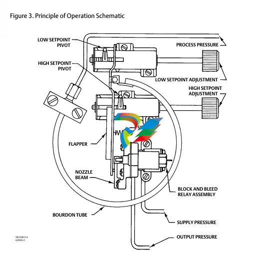
Principle of Operation
Refer to figure 3.
Process pressure is connected to the Bourdon tube
sensing element. While the process pressure remains
in the adjusted set ranges (between the low set point
and the high set point), the flapper does not contact
either set point pivot. This keeps the nozzle capped
and maintains full output pressure.
As the process pressure decreases below the low set
point value, the radius of arc of the Bourdon tube
contracts. This causes the flapper to contact the low
set point pivot and uncap the nozzle, which blocks
supply pressure and vents (bleeds) output pressure. As
the process pressure increases above the high set
PROCESS PRESSURE
LOW SETPOINT ADJUSTMENT
HIGH SETPOINT
ADJUSTMENT
SPRING
BLOCK AND BLEED
RELAY ASSEMBLY
SUPPLY PRESSURE
OUTPUT PRESSURE
point value, the radius of arc of the Bourdon tube
extends. This causes the flapper to contact the high set
point pivot, also uncapping the nozzle and providing
block-and-bleed action. When the process pressure
returns to the set range, the nozzle is again capped,
switching the relay back to maintain full output
pressure.
Performance
The performance characteristics discussed in the
Performance in Percentage of Bourdon Tube Rating
specification on page 3 and shown in figure 4
illustrate several important functional parameters.
SL represents the low set point and SH represents the
high set point. The set range capability is 3 to 97
percent of the Bourdon tube rating. However, with a
single high-low unit or a high-only/low-only pair, there
is a limit on how close to each other the set points can
be adjusted. This limit is defined as set point ΔPMIN and
is shown as SL′ and SH′.
Trip-to-reset is the combined effect of pilot deadband
and hysteresis. After the pilot has tripped, it
automatically resets when the process pressure
returns to the set range. However, full output pressure
is not instantaneous. The difference between the set
point and reset to full output pressure is the
trip-to-reset zone. This parameter is also a function of
the Bourdon tube rating as shown in figure 4 and
discussed in the Performance in Percentage of
Bourdon Tube Rating specification on page 3.
Repeatability is the switch point deviation around the
set point as a percentage of the Bourdon tube rating.
Applications
Figure 5 shows some of the many ways in which the
4660 high-low pressure pilot may be connected to
accommodate requirements for single and dual
outputs as well as single and dual process pressure
lines. Examples A and D in figure 5 show how a pair of
high-only and low-only pilots are connected to obtain
closer set points as specified by the set point ΔPMIN
values in tables 1 and 2. Example B or C shows
connections for a two-segment flow line configuration
that adheres to API Specification RP14C. Example E
shows a typical connection to an electrical pressure
switch
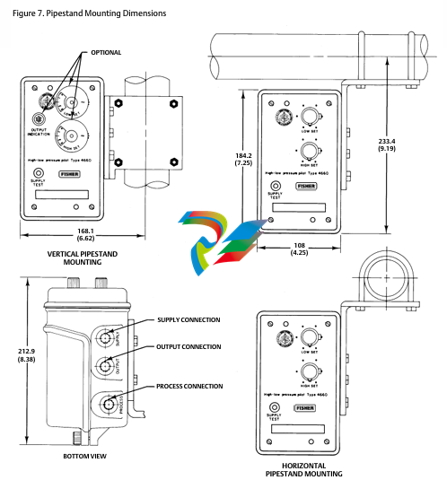
Installation
Normal installation is with the pilot mounted vertically
and the connections for process pressure, supply
pressure, and output pressure facing down. The supply
medium should be regulated dry air or natural gas with
solid particles removed.
Figures 6 and 7 illustrate the mounting dimensions
and the location of the pressure connections.
Ordering Information
When ordering, specify:
Application
Bourdon tube rating and material
Composition, pressure, and temperature of the
process fluid
Ambient temperature range
Description of application
Construction
Refer to the Specifications table. Review the
information under each specification and in the
referenced tables; specify the desired selection
whenever there is a choice to be made
-
 Hirschmann M1-8SFP Switche
 -
 Hirschmann Industrial Ethernet Ruggedized Switch MACH1000 Family
 -
 Basler Electric, Solid State Protective Relay, BE1-60
 -
BASLER ELECTRIC SR4A-2B15B3A Static Voltage Regulator
-
.png) BASLER ELECTRIC EXCITER DIODE MONITOR EDM-200
BASLER ELECTRIC EXCITER DIODE MONITOR EDM-200 -
.png) BASLER ELECTRIC DECS125-15-B2C5 DIGITAL EXCITATION CONTROL SYSTEM V 2.0.9
BASLER ELECTRIC DECS125-15-B2C5 DIGITAL EXCITATION CONTROL SYSTEM V 2.0.9 -
 BASLER ELECTRIC BE1-851 OVERCURRENT PROTECTION RELAY MECHANISM
 -
 Basler Electric BE1-51A / BE151A
 -
 Basler Electric BE1-40Q Loss of Excitation Relay
 -
 Basler Electric BE1-87G Variable Percentage Differential Relay
 -
 Basler Electric BE1-11 Protection System I5A3M2P2N0EA00
 -
 BASLER ELECTRIC DECS-200-1C Digital Excitation Control System
 -
 Basler Electric / Kohler BE1-11g Generator Protection Relay G5A3M2J2N0E000
 -
BASLER ELECTRIC DECS125-15 DIGITAL EXCITATION CONTROL SYSTEM
-
 BASLER ELECTRIC BE1-951 OverCurrent Protecton System
 -
Basler Electric DECS-200-1L Digital Excitation Control System
-
 Basler Electric DGC-2020HD-5NS1DNSBA Digital Genset Controller -
 -
 BASLER ELECTRIC BE1-81T1EE1WA0N1F / BE181T1EE1WA0N1F
 -
 BASLER ELECTRIC BE1-25M1EA6PN5R1F / BE125M1EA6PN5R1F
 -
 BASLER ELECTRIC DECS-250-LN1SN1N DIGITAL EXCITATION CONTROL SYSTEM
 -
Basler Electric DECS-250-CN2CN 1N Digital Excitation Control System Unit
-
 BASLER ELECTRIC DECS-300-C0N0 DIGITAL EXCITATION CONTROL SYSTEM
 -
 BASLER ELECTRIC BE1-87T-A1E-A1J-D0S1F / BE187TA1EA1JD0S1F
 -
BASLER ELECTRIC BE1-11-G6D1M0J2P0E000 Protection System
-
 BASLER ELECTRIC BE1-GPS100-E4N1H1N GENERATOR PROTECTION SYSTEM
 -
 Jaquet Relay card (Auxiliary module) FTV 3090 377Z-03985
 -
 Jaquet Trip Chain Control card FTBU 3034 377Z-05030
 -
 Jaquet with input card -E04 FTFU 3024 -E04 377Z-05855
 -
 Jaquet with input card -E03 FTFU 3024- E03 377Z-03983
 -
 Jaquet FTFU 3024- E02 377Z-03982 with input card -E02
 -
 Jaquet FTFU 3024-E01 377Z-03981 with input card -E01
 -
 Hirschmann RS20-2400T1T1SDAE Industrial Managed Ethernet Switch
 -
 Hirschmann BELDEN EAGLE30-04022O6TT999SCCV9HSE3F
 -
 Hirschmann MM3-2FXS2/2TX MICE Media Module
 -
 Hirschmann RS20-1600M2M2SDAPHC08.0.05 Industrial Managed Switch
 -
 Hirschmann OZD Profi 12M G12-1300 PRO Fieldbus Repeater
 -
 Hirschmann SPIDER 4TX/1FX-ST EEC Industrial Ethernet Switch
 -
 Hirschmann MM2-2FXM3/2TX1 MICE Media Module
 -
 Hirschmann RS20-2400M2M2SDAPHC09.0.14 Industrial Switch
 -
 Hirschmann RS20-0400M2M2SDAEHC07.1.05 OpenRail Switch
 -
 Hirschmann OZD Profi 12M G12-EEC Fieldbus Repeater
 -
 HIRSCHMANN MDA422-1/2-3.5c-23/46 sensor
 -
Hirschmann RS30-2402T1T1SDAUHC Managed Industrial Switch
-
 Hirschmann OZD GENIUS G12 Industrial Switche
 -
 Hirschmann OZD 485 G12-1300 PRO Fieldbus Repeater
 -
 Hirschmann MM2-2FXM2 MICE Media Module
 -
 Hirschmann RS20-1600S2T1SDAUHC Managed Industrial Switch
 -
 Hirschmann MS20-0800SAAEHH04.2.04 MICE Switch
 -
 Hirschmann SPIDER 4TX/1FX EEC Unmanaged Industrial Switch
 -
 HIRSCHMANN MS4128-L3P EEC Managed Industrial Ethernet Switch
 -
 HIRSCHMANN RS20-0400M2T1SDAPHC08.0.01 Managed Switch
 -
 ETEL EA-S0M-400-40/80A-0000-00 AccurET Modular Power Supply
 -
 ETEL EA-B0I-0-0-0000-00 Backplane Interface Board
 -
 ETEL EA-P2M-400-15/40A-0100-00 Position Controller
 -
ETEL EA-P2M-400-15/40A-0000-00 Position Controller
-
 ETEL EA-P2M-400-10/20A-0100-01 Position Controller
 -
 ETEL EA-P2M-400-10/20A-0000-01 Position Controller
 -
 ETEL EA-P2M-400-5/10A-0100-01 Position Controller
 -
 ETEL EA-P2M-048-2.5/5A-0000-01 Modular Position Controller
 -
 ETEL EA-S0M-300-40/80A-0000-00 Power Supply Module
 -
 ETEL EA-P2M-300-07/15A-0100-01 Position Controller
 -
 ETEL EA-P2M-300-07/15A-0000-01: Modular Position Controller
 -
 ETEL EA-P2M-300-4/7.5A-0100-01 Overview
 -
 Basler Electric MOC2. Motor Operated Potentiometer
 -
 Basler Electric BE1-11 RTD Module, Resistance Temperature Detector
 -
 Basler Electric RDP-110C, Remote Display Panel
 -
 Basler Electric VRM-2020. Voltage Regulation Module
 -
 Basler Electric IDP-1500. Interactive Display Panel
 -
 Basler Electric AEM-2020. Analog Expansion Module
 -
 Basler Electric IDP-2020. Interactive Display Panel
 -
 Basler Electric CEM-2020. Contact Expansion Module
 -
 Basler Electric CEM-125. Contact Expansion Module
 -
 Basler Electric BE2000E, Digital Voltage Regulator
 -
 Basler Electric SMC-150. Synchronous Motor Controller
 -
 Basler Electric AVC125-10. Voltage Regulator
 -
 Basler Electric BE1-25. Sync-Check Relay
 -
 Basler Electric DGC-2020ES, Digital Genset Controller
 -
 ETEL EA-P2M-400-5/10A-0000-01 Position Controller
 -
 Basler Electric BE1-64F, Ground Fault Relay
 -
 Basler Electric BE1-79M, Multi Shot Reclosing Relay
 -
 Basler Electric BE1-81O/U, Digital Frequency Relay
 -
 Basler Electric BE1-87B, High Impedance Bus Differential Relay
 -
 Basler Electric BE1-79A, Reclosing Relay
 -
 Basler Electric BE1-27. BE1-59. BE1-27/59. Voltage Relay
 -
 Basler Electric SMC-250. Synchronous Motor Controller
 -
 Basler Electric SGC-250N, Synchronous Generator Controller
 -
 Basler Electric SGC-250. Synchronous Generator Controller
 -
 Basler Electric BE1-50/51 Plug and Play and Retrofit Relays
 -
 Basler Electric DECS-2100. Digital Excitation Control System
 -
 Basler Electric DECS-250E, Digital Excitation Control System
 -
 Basler Electric BE1-700V, Voltage Only Digital Protective Relay
 -
 Basler Electric DECS-250. Digital Excitation Control System
 -
 Basler Electric DECS-450. Digital Excitation Control System
 -
 Basler Electric DECS-150. Digital Excitation Control System
 -
 Basler Electric ES-49. Temperature Relay
 -
 Basler Electric ES-81O/U, ES-81O,ES-81U Overfrequency Relay
 -
Basler Electric ES-74V, DC Voltage Sensing Relay
-
Basler Electric ES-27/59. Under/Overvoltage Relay
-
 Basler Electric ES-27. Undervoltage Relay
 -
 Basler Electric ES-25. Sync-Check Relay
 -
 Basler Electric ES-47, ES-47N Phase Sequence Relay
 -
Basler Electric ES-37.ES-37/51 Undercurrent Relay
-
 Basler Electric ES-32. Reverse Power Relay
 -
Basler Electric ES-59. Overvoltage Relay
-
 Basler Electric ES-55. Power Factor Relay
 -
 Basler Electric DGC-2020HD, Digital Genset Controller
 -
 Basler Electric BE1-FLEX, Protection, Automation, and Control System
 -
 Schneider GUTOR OC0935 Power Factor Sampling Board
 -
 Schneider GUTOR OC0922 Analog Signal Isolation Board
 -
 Schneider GUTOR OC0908 Battery Voltage Detection Board
 -
Schneider GUTOR OC0947 Temperature / IGBT Sampling Board
-
 Schneider GUTOR OP2601 Communication Expansion Board
 -
 Schneider Electric GUTOR OP2312 bypass control board
 -
 Schneider Electric GUTOR OP2130 Cooling Fan Monitoring & Control Board
 -
 Schneider Electric GUTOR OP2010 Battery Test Board / Battery Management Diagnostic Card
 -
Schneider Electric GUTOR OP2552 Three-phase Power Connection Board Assembly
-
 Schneider Electric GUTOR OP1922A Parallel Control Board / Load-Sharing Synchronization Module
 -
 Schneider Electric GUTOR OP6290B Inverter Feedback Acquisition Board / Signal Scaling Module
 -
Schneider GUTOR OP6280 Basic Signal Board
-
Schneider Electric GUTOR OP2456 / OP2456B Main control board
-
 Schneider Electric GUTOR OP2452 Power Plug-in Panel
 -
 Schneider Electric GUTOR OP2450 Parallel Communication Board
 -
Schneider Electric GUTOR OP2406 Interface Fuse Monitoring Board
-
 Schneider Electric GUTOR OC0919 High-Power Semiconductor Module
 -
 Schneider Electric GUTOR OP6281A System Logic Interface Board
 -
 Schneider Electric GUTOR OP6285A Power Signal Acquisition Board
 -
 Schneider Electric GUTOR OP2438 Fan Monitor & Drive Protection Board
 -
Schneider Electric GUTOR OP2446 Main Control CPU Board


