
AlstomEthernet Manual
Preface This document
The Ethernet Manual is the same for all ALSTOM Power Service controllers equipped with Ethernet. Therefore reference to specific controller names such as EPIC or EFFIC will not be used from this point, instead the general term “controller” will be used. This Ethernet Manual contains information for the Designing Engineers on the pre-commissioning of the Ethernet network. It also contains information for Shift Operators on the PC-MTU software, which is a software used for setting up, operating and monitoring an installation of several controllers in the network. The PC-MTU software is linked together with the web pages on the controllers built-in web server. These web pages are the interface used to configure each individual controller. For more information, see Operator’s & Installation Manual.
Related documents
The following documents are related to the Ethernet Manual:
• Ethernet Manual- (this document).
• EPIC/EFFIC Operator’s & Installation Manual - contains information for all groups of users from the installation and commissioning to daily operation and tuning of the cleaning process. -Shift Supervisor Advanced operation and taking action on all alarms that may occur. -Process Engineer From small to medium scale diversions from factory settings in order to optimize the cleaning process. -Commissioning Engineer All stages of the commissioning. -Installation personnel (mechanical and electrical) Mechanical, electrical and communication installation.
• Ethernet Manual- (this document). • EPIC/EFFIC Operator’s & Installation Manual - contains information for all groups of users from the installation and commissioning to daily operation and tuning of the cleaning process. -Shift Supervisor Advanced operation and taking action on all alarms that may occur. -Process Engineer From small to medium scale diversions from factory settings in order to optimize the cleaning process. -Commissioning Engineer All stages of the commissioning. -Installation personnel (mechanical and electrical) Mechanical, electrical and communication installation.
Ethernet standard
Ethernet is a network standard of communication. The most widely used for LAN communication, Ethernet typically runs at 100 megabytes per second. All new controllers developed by ALSTOM Power Service use the Ethernet standard for communication. The following chapter describes what type of equipment is needed to successfully set up a Ethernet
General information on Ethernet
For general information on Ethernet there is a lot of information available both on the Internet and in published books. A good place to start is one of the following websites:
• Cisco Internetworking Technology Overview for Ethernethttp://www.cisco.com/univercd/cc/td/doc/cisintwk/ito_doc/ethernet.htm
• Howstuffworks http://computer.howstuffworks.com/ethernet.htm For specific information on Industrial Ethernet standards the Industrial Ethernet Planning and Installation Guide is recommended, can be down loaded from the following website:
• Iaonawww.iaona.org
Typical Ethernet network
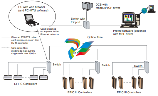
1.3. Ethernet switch
The Ethernet switch shall meet the following standards: • EMC immunity for industry EN 50082-2 or EN 61000-6-2 Alstom Power Service has successfully used the switches from HMS Industrial Networks, Sweden and different types of switches from Hirschman Electronics
1.4. Ethernet hub
Ethernet hub should not be used in a new installation, because it will decrease the performance of the network. With a hub in the network it is also more difficult to calculate the allowed cable lengths
1.5. Connection to controller
The Ethernet board connection on the controller is of the following type: • RJ45 10/100M/bit auto negotiation
1.6. Cables
Cat 5E FTP cables with RJ45 connectors are recommended for the Ethernet network.
1.7. Ethernet ports and protocols
The following Ethernet ports are used
• Port 20, 21 for FTP
• Port 80 for HTTP
• Port 502 for Modbus/TCP data
• Port 3 250 for PC-MTU - IP config
• Port 49 200, 49 201 for the master functionality and PC-MTU.
1.8. Ethernet routers
Routers should not be installed in the EPIC III Ethernet network. The PCMTU and master functionality will not function properly through it
Setup Ethernet network
The following chapter describes how to install the software and how to setup your Ethernet network. The installation procedure is the same for all ALSTOM Power Service controllers equipped with Ethernet. Therefore reference to specific controller names such as EPIC or EFFIC will not be used from this point, instead the general term “controller” will be used.
Software installation
Insert the PC-MTU software CD into your CD-ROM drive. 2. Follow the installation instructions.
System requirements
• PC with 300 megahertz or higher processor clock speed recommended.
• Intel Pentium/Celeron family, or AMD K6/Athlon/Duron family, or compatible processor recommended.
• 128 megabytes (MB) of RAM or higher recommended.
• Super VGA (1024 x 768) or higher-resolution video adapter and monitor.
• CD-ROM or DVD drive.
• Keyboard and Microsoft Mouse or compatible pointing device.
• Microsoft Windows® 2000 or Microsoft Windows XP®
• Microsoft Internet Explorer® 6.0 or higher.
2.3. Assigning IP address
The IP address is used to identify each controller on the Ethernet network. Therefore, each controller on the network must have a unique IP address.
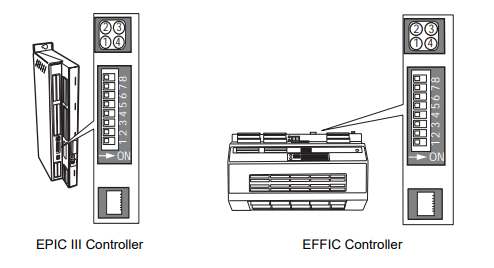
2.3.1. The Ethernet board location
To manually assign an IP address to a controller its Ethernet boards dip switches are used. The location of the Ethernet board differs depending on product, see figure 2 below.
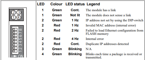
2.3.2. Ethernet LEDs
The Ethernet board has four LEDs carrying the following information:
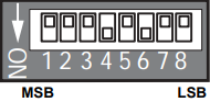
2.3.3. Assigning the IP address to the controller There are many different ways to assign ip addresses, in this manual the three most common will be described in the three following sections. The Ethernet board has a default IP address setting of: IP address:192.168.0.X The X in the IP address can be set from 1 to 255 by the configuration switch on the ethernet board. The switch represents the binary value of the X value in the IP address. Example: The switches are set to 00010100 (20 decimal). The IP address will be set to 192.168.0.20
2.3.4. Using configuration switch 1. Make sure that the controller is switched Off. 2. Use the configuration switch to assign a unique ip number to the controller, a number not used by any other nodes in the network. 3. Switch On the controller. 4. Repeat step 1-3 with all the controllers in the network. 5. Now the IP address of the PC has to be set (the PC that is used for running the PC MTU software and browsing the web pages). 6. On the PC - click the START button and select Control Panel. 7. In Control Panel select Network and Dial-up connections and then Local Area Connection. 8. Select Properties and highlight Internet Protocol (TCP/IP) and select Properties. 9. Click the radio button Specify an IP Address. 10. In the IP address field assign a unique ip number not used by any other nodes in the network to the PC e.g. 192.168.0.100. The Subnet mask will normally be automatically filled in (255.255.255.0). Click OK and close all windows. 11. To complete the setup start the PC-MTU program. 12. From the menu Choose Advanced > Ip config.2.3.5. Using specific IP numbers
To setup the controllers execute step 1-17 in section Using configuration switch on page 7. 2. Assign the specific IP number to each individual controller. 3. Assign the specific Subnet to each individual controller. 4. Assign the specific Gateway to each individual controller. 5. To save the information on the controller flashdisc click on Config nodes. 6. Switch Off all controllers. 7. Reset the configuration switch on all controllers, see figure to the right. 8. Switch On all controllers to start using the values stored in the memory. 9. Execute step 18-19 in section Using configuration switch on page 7.
2.3.6. Using DHCP 1. To setup the controllers execute step 1-17 in section Using configuration switch on page 7. 2. Mark the checkbox DHCP on all the controllers 3. To save the information on the controller flashdisc click on Config nodes. 4. Switch Off all controllers. 5. Reset the configuration switch on all controllers 6. Switch On all controllers to start using the values stored in the memory. 7. Execute step 18-19 in section Using configuration switch on page 7.
-
 Beckhoff C6640-0040 Control Cabinet Industrial PC 7-Slot
 -
 BECKHOFF CONTROL CABINET INDUSTRIAL PC - C6930-1062-0050
 -
 Beckhoff Automation EtherCAT Terminal EK1100 EK1122
 -
 Beckhoff CP6533-0001-0060 IPC
 -
 Beckhoff EK9500 | EtherNet/IP™ Bus Coupler
 -
 Beckhoff CP6202-1047-0050 - An industrial-grade embedded panel computer.
 -
 Beckhoff C6650-0040 Industrial PC
 -
 BECKHOFF CX5230-0185 / 000119805 PLC Module
 -
 BECKHOFF EL4732 | EtherCAT Terminal, 2-channel analog output, voltage, ±10 V, 16 bit, oversampling
 -
 Beckhoff CP6202-0001-0010 Economy Built-In Panel
 -
 Beckhoff AX5206-0000-0202 Digital Compact Servo Drives 2-channel
 -
 Beckhoff CP6606-0001-0020 7-inch Economy Panel PC
 -
 Beckhoff CPU basic module CX2020-0155 + power supply module CX2100-0004
 -
 Beckhoff CP2913-000 Multi-Touch Display
 -
 Beckhoff CP6500-1012-0060 14250369 Control Cabinet
 -
 Beckhoff CP7902-0001-0000 Economy Control Panel with DVI/USB Extended interface
 -
 Beckhoff C6920-0010 Control cabinet Industrial PC
 -
 BECKHOFF C3640-0050 Build-in Industrial PCs
 -
 Beckhoff KL6023-0000 KL6023 EnOcean Wireless-Adapter
 -
 Kollmorgen AKM54G-ANC2DB00 servo motor
 -
 Kollmorgen AKD-P00606-NBCN-0000 Servo Drive
 -
Kollmorgen S200 Series S20350-VTS SERVO DRIVE
-
 KOLLMORGEN AKD-P00606-NBCC-I000 SERVO DRIVE
 -
 Kollmorgen MV65WKS-CE310/22PB Servo Drive Control Module
 -
 Kollmorgen S20360-VTS-021 Servo Drive
 -
 KOLLMORGEN CR06550 High-precision digital servo amplifier
 -
 KOLLMORGEN DBL5N01050-03S-VV0-S40 3-Phase AC Synchronous Brushless Servo Motor
 -
 KOLLMORGEN S70301-NANANA-024 SERVO DRIVE
 -
 Kollmorgen S20360-VTS S200 Series Servo Drive
 -
 Kollmorgen RBE-03011-A00 Brushless Frameless Servo Motor
 -
 KOLLMORGEN AKD-T00306-NBAN-0000 INPUT SERVO DRIVE
 -
 KOLLMORGEN S700 Servo Controller S70302-NANANA
 -
 Kollmorgen AKD-P00607-NBEC-0000 400/480VAC 4.40KVA Servo Drive.
 -
 KOLLMORGEN S70102-NANANA SERVO DRIVE
 -
 KOLLMORGEN AKM21E-ANSNEH02 PM Servo Motor & PRD-AMPE25EB-00 Servo Drive Array
 -
 KollMorgen SC1R06260 Servo Drive 1.4/2.2 KVA 115230 Vac
 -
 Kollmorgen AKD-P00306-NBAN-0000 Servo Drive
 -
Kollmorgen TTB2-2042-3052-A DC Motor Industrial Drive 5.5A 185 oz/in
-
 KOLLMORGEN SERVOSTAR 610-AS SERVO AMPLIFIER_SERVOSTAR610AS_S61001
 -
 KOLLMORGEN PRD-0016400P-10 & PRD-0016600D-30 Axis Control System Modules
 -
KOLLMORGEN Seidel DBL5N01700-03S-000-S40 Servo Motor
-
 Hirschmann RS20-1600M2T1SDAEHH03.1.02 Rail Switch
 -
 Hirschmann BRS30-24TX Industrial Rail Switch
 -
 Hirschmann RSPM20-4T14T1EV9HHS999.9.99 Managed Ethernet Switch
 -
 Hirschmann BELDEN RS40-0009CCCCSDAPHH09.0.14 / RS400009CCCCSDAPHH09014
 -
Hirschmann RS40 Rail Switch RS40-0009CCCCSDAE
-
 Hirschmann BELDEN RS30-0802T1T1SDAP / RS300802T1T1SDAP Fully Managed Layer 2 Compact Rail Switch
 -
 Hirschmann BELDEN RS20-0800M2M2SDAUHH / RS200800M2M2SDAUHH
 -
 Hirschmann EAGLE30-04022O6TT999SCCY9HSE3F Industrial Firewall Router Switch
 -
 Hirschmann RS20-1600T1T1SDAEHH09.0.14 RS20 Rail Mount Ethernet Switch
 -
 Hirschmann EAGLE0200T1T1TDDY90000HHE05.3.03 Industrial Security Router
 -
Hirschmann - BELDEN MIPP-AD-1L9P
-
 HIRSCHMANN RSPM20-4Z64Z6TV9HHS9 942 106-999 RAIL SAFETY SWITCH
 -
 HIRSCHMANN FIBEROPTIC MODULE FIP P/N: OZDFIPG3T
 -
 HIRSCHMANN RS20-1600M2M2SDAUHH Ethernet rack-mounted switch
 -
 HIRSCHMANN BELDEN RS20-0400T1T1SDAEHH04.0.01 / RS200400T1T1SDAEHH04001
 -
HIRSCHMANN MM2-4FXM3 MICE Media Module
-
HIRSCHMANN RS20-0800M2M2SDAE Industrial Ethernet Rail Switch
-
 Hirschmann RS20-2400T1T1SDAP / RS20-2400T1T1SDAPHH05.0.02
 -
 GE MLJ1005B010H00C MLJ Digital Synchromism Check
 -
 ALSTOM MICROTECH DX21-M2 Digital Excitation Controller
 -
HIRSCHMANN BRS20-1200ZZZZ-STCY99HHSES
-
 HIRSCHMANN MM3-4FXM2 MICE Media Module
 -
Hirschmann RSB20-0800T1T1SAABHH 8Port ENet Rail Switch RSB20
-
 Hirschmann MACH102-8TP Ethernet Switch
 -
 SAACKE DDZ-M marine steam pressure atomizer
 -
 SAACKE SKV-A marine rotary cup atomizer
 -
 SAACKE Seavis HMI05e
 -
 Kollmorgen MMC-SD-2.0-230 Servo Drive 100-240VAC 2KW 10A Output 3PH 100-240VAC
 -
 Kollmorgen Servo drive CR10550
 -
 Kollmorgen AKD-P01207-NACN-0054 Servo Driver
 -
 Kollmorgen S406M-CA-036 Servostar
 -
.png) Kollmorgen AKD-B02407-NAAN-0000 Digital Servo Drive
Kollmorgen AKD-B02407-NAAN-0000 Digital Servo Drive -
 Kollmorgen SERVOSTAR S406AM-CA Digital Servo Drive
 -
 KOLLMORGEN SERVOSTAR 603-AS SERVO AMPLIFIER_SERVOSTAR603AS_S60301
 -
Kollmorgen S700 Servo Controller (S70602-NANANA-NA)
-
 Kollmorgen MPK411 controller
 -
 KOLLMORGEN MMC-SD-1.3-460-D Smart Drive
 -
 KOLLMORGEN AKM21C-CKB2AA-00 / AKM21CCKB2AA00 Servomotor
 -
 BECKHOFF AX5106-0000-0200 | Digital Compact Servo Drives 1-channel
 -
 BECKHOFF C3620-0000 INDUSTRIAL COMPUTER (MOTORSHELVES)
 -
 Beckhoff EK1960-0000 TwinSAFE Compact Controller
 -
 Beckhoff C6930-0050 Control Cabinet Industrial PC
 -
 Beckhoff CP7711-0001-0030 Industrial Computer Detection
 -
 Beckhoff CX1001-0111 Embedded PC CPU Module
 -
 Beckhoff C6017-0020 | Ultra-compact Industrial PC
 -
 Beckhoff EK1322 | 2-port EtherCAT P junction with feed-in
 -
 Beckhoff CP2219-0010 Panel
 -
 BECKHOFF C6015-0020 ULTRA COMPACT INDUSTRIAL PC
 -
 BECKHOFF CX2030-0120/Standard CPU Module Embedded PC Windows PLC controller
 -
 Beckhoff CP7721-1090-0020 Panel PC
 -
 Beckhoff PC CPU Module CX5130-0175
 -
 Beckhoff C6920-0050 Control Cabinet
 -
 Beckhoff EL6631 EtherCAT 2-Port Communication Interface, Profinet RT Controller
 -
 Beckhoff CP6202-0001-0060 touch screen panel PC
 -
 Beckhoff CP3916-1002-0000 Multi-Touch Control Panel
 -
 Beckhoff EP1809-0021 | EtherCAT Box, 16-channel digital input, 24 V DC, 3 ms, M8Preferred type
 -
 Beckhoff CX8190 PLC Embedded Industrial PC Ethernet Controller
 -
 Beckhoff CX2100-0914 Power Supply for External
 -
 Beckhoff Automation CP6906-0001-0000 HMI
 -
 Beckhoff EP7342-0002 Module
 -
 Beckhoff CX1020-0112 / CX1100-0910 / CX1020-N010 / CX1100-0003 Windows CPU
 -
 Beckhoff EP7211-0034 EtherCAT Box 1 Channel Motion Interface
 -
 Beckhoff C6240-0030 Control cabinet Industrial PC
 -
 beckhoff motherboard CB1052-0004 CB1052-0004
 -
 Beckhoff AX2006-AS Servo Drive / Variable Frequency Drive
 -
BECKHOFF CP6207-0001-0020 NSMP
-
 Beckhoff C6930-1142-0060 Industrial Computer
 -
 Beckhoff FC7501-0000 interface card
 -
 Beckhoff CX5140-0175 Embedded PC PLC CPU CX5140 Industrial Controller
 -
 Beckhoff CP7802-1100-0010: High-End IP65 Control Panel with DVI/USB Extended Interface
 -
BECKHOFF CP3716-1058-0010 CONTROL PANEL
-
 Beckhoff AX8108-0000 Single-Axis Module
 -
 Beckhoff CU8851-0000 | USB extension, USB Extended 2.0 receiver box
 -
Beckhoff C6017-0030 | Ultra-compact Industrial PC
-
 Beckhoff CX1001-0120/CX10010120.cx1000-n001.cx1000-n000 System Overview
 -
 Beckhoff CPU Module CX5140-0155/4GB CPU Module
 -
 Beckhoff CP6533-0001-005: Built-in Panel PC with High-Definition Multi-Touch Control
 -
 Beckhoff EL5042 | EtherCAT Terminal, 2-channel encoder interface, BiSS® C
 -
 Beckhoff C6920-1080-0040: Premium Control Cabinet Industrial PC
 -
 Beckhoff C6920-0060 | Control cabinet Industrial PC
 -
 Beckhoff Embedded-PC CX5010-1121
 -
 Beckhoff CB3050-0010 Mainboard Motherboard
 -
 Beckhoff PLC module CX1020-0000 Basic CPU module (service phase)
 -
 Beckhoff CP7812-1056-0010 15" Multitouch Display Control Panel
 -
 Beckhoff CX5120-0115 /2GB Controller Module
 -
 Beckhoff CP7201-1000-0000 Industrial Panel PC
 -
 Beckhoff Servo Motor AM8061-0JH1-0000


