
AlstomT1693EN Technical Manual Rev. 09
Care has been taken with the design of this product to ensure that it is safe. However, in common with all
products of this type, misuse can result in injury or death. Therefore, it is very important that the
instructions in this manual and on the product are observed during transportation, commissioning,
operation, maintenance and disposal.
This technical manual must be regarded as part of the product. It should be stored with the product and
must be passed on to any subsequent owner or user.
Local safety laws and regulations must always be observed.
Persons working on the product must be suitably skilled and should have been trained in that work for
these products.
The product is a component designed for incorporation in installations, apparatus and machines.
The product must not be used as a single item safety system. In applications where maloperation of the
product could cause danger, additional means must be used to prevent danger to persons.
Product approvals and certifications will be invalidated if the product is transported, used or stored outside
its ratings or if the instructions in this manual are not observed.
Third party approvals to safety standards UL508C and CSA C22.2 No 14 are marked on the product.
In the European Union
• Products within the scope of the Low Voltage Directive, 2014/35/EU are CE marked.
• The product complies with the essential requirements of the EMC directive 2014/30/EU, when
installed and used as described in this manual. The requirements of the EMC Directive should
be established before any installation, apparatus or machine which incorporates the product
is taken into service.
• A machine must not be taken into service until the machine has been declared in conformity
with the provisions of the Machinery Directive, 2006/42/EC.
INTRODUCTION
1.1 GENERAL DESCRIPTION
An MV3000e DELTA a.c. drive is used to control a motor, generator, or power conditioning application.
It uses a modular approach which allows the use of a small number of common components to create a
large number of system variants
Advantages Of The Modular System
• The DELTA transistor and rectifier modules are of a standard mechanical design, using the
same mounting method and dimensions;
• DELTA rectifier and transistor modules can be connected in parallel to provide a wide range of
power levels;
• Modular construction makes maintenance and repair work simple, and enables rapid module
replacement;
• DELTA transistor and rectifier modules can be withdrawn on a simple slide system for ease of
assembly and maintenance.
• Ease of handling – smaller, lighter modules are assembled to form large drives.
DELTA Product Range
• Rectifier module;
• Transistor modules;
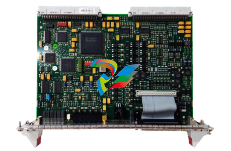
• MV3000e Controller
• SMPS (Switch Mode Power Supply) units;
• User I/O termination panel;
• MVM (Mains Voltage Monitor);
• DDM (Drive Data ManagerTM)– Keypad;
• Reactors and transformers;
• Installation accessories (mounting kits and control cables).
ASSOCIATED MANUALS
• T1676 – MV3000e Getting Started Manual (for rectifier fed systems);
• T1679 – MV3000e Software Manual (and Firmware Supplement T2154);
• T2002 – MV3000e Getting Started Manual (for AEM systems).
The T1676 and T2002 manuals include commissioning and operating details for the complete MV3000e
DELTA drive.
The T1676, T1679 and T2002 manuals should be regarded as part of the DELTA product. Individual DELTA
component instructions sheets that may also be required are shown below:
• T1694 MVS3007-4002 - Profibus Field Coupler 12 Mb/s;
• T1915 MVS3000-4001 – Drive Data Manager TM (keypad);
• T1916 MVS3001-4001 - Keypad mounting kit;
• T1930 MVC3006-4003 – Mains Voltage Monitor (MVM);
• T1968 MVS3011-4001 - CANbus communications module;
• T1973 MVC3003-40xx – Switch Mode Power Supply (SMPS) Module;
• T2034 MVS3012-400x - Ethernet interface;
• T2100 MVDL800 DELTA Transistor Module;
• T2101 MVDL1000 DELTA Transistor Module;
• T2112 MVC3001-400x – DELTA Controller
Section 1 – Introduction
• Overview of the main concepts used in DELTA drives;
Section 2 – Specifications
• Common environmental data for the DELTA product range;
• Gives individual DELTA component data.
Section 3 – Complete Drive Module (CDM) Design
• Guidance for component selection;
• Enclosure design;
• Cooling system design;
Section 4 – Power Drive System (PDS) Design
• Motor requirements;
• Motor and supply cable selection;
• Encoder details.
Section 5 – Complete Drive Module (CDM) Assembly
• Guidance for assembly of DELTA components into an enclosure.
Section 6 – CDM Commissioning
• Guidance for commissioning the CDM, including electrical safety checks and functional
testing.
Section 7 – PDS Commissioning
• Guidance for commissioning the CDM in the final location.
Section 8 – Maintenance
• Diagnostic information;
• Preventative maintenance;
• Module replacement.
Section 9 – Disposal
Appendices
• Mechanical drawings of DELTA components;
• Electrical connection diagrams
• Torque values.
DRIVE CONFIGURATIONS
A DELTA drive consists of two ‘bridges’ – the network bridge and the machine bridge.
Two generic configurations are available, each with a different network topology:



.png)


.png)


.png)


