
AlstomT1693EN Technical Manual Rev. 09
Care has been taken with the design of this product to ensure that it is safe. However, in common with all
products of this type, misuse can result in injury or death. Therefore, it is very important that the
instructions in this manual and on the product are observed during transportation, commissioning,
operation, maintenance and disposal.
This technical manual must be regarded as part of the product. It should be stored with the product and
must be passed on to any subsequent owner or user.
Local safety laws and regulations must always be observed.
Persons working on the product must be suitably skilled and should have been trained in that work for
these products.
The product is a component designed for incorporation in installations, apparatus and machines.
The product must not be used as a single item safety system. In applications where maloperation of the
product could cause danger, additional means must be used to prevent danger to persons.
Product approvals and certifications will be invalidated if the product is transported, used or stored outside
its ratings or if the instructions in this manual are not observed.
Third party approvals to safety standards UL508C and CSA C22.2 No 14 are marked on the product.
In the European Union
• Products within the scope of the Low Voltage Directive, 2014/35/EU are CE marked.
• The product complies with the essential requirements of the EMC directive 2014/30/EU, when
installed and used as described in this manual. The requirements of the EMC Directive should
be established before any installation, apparatus or machine which incorporates the product
is taken into service.
• A machine must not be taken into service until the machine has been declared in conformity
with the provisions of the Machinery Directive, 2006/42/EC.
INTRODUCTION
1.1 GENERAL DESCRIPTION
An MV3000e DELTA a.c. drive is used to control a motor, generator, or power conditioning application.
It uses a modular approach which allows the use of a small number of common components to create a
large number of system variants
Advantages Of The Modular System
• The DELTA transistor and rectifier modules are of a standard mechanical design, using the
same mounting method and dimensions;
• DELTA rectifier and transistor modules can be connected in parallel to provide a wide range of
power levels;
• Modular construction makes maintenance and repair work simple, and enables rapid module
replacement;
• DELTA transistor and rectifier modules can be withdrawn on a simple slide system for ease of
assembly and maintenance.
• Ease of handling – smaller, lighter modules are assembled to form large drives.
DELTA Product Range
• Rectifier module;
• Transistor modules;
• MV3000e Controller
• SMPS (Switch Mode Power Supply) units;
• User I/O termination panel;
• MVM (Mains Voltage Monitor);
• DDM (Drive Data ManagerTM)– Keypad;
• Reactors and transformers;
• Installation accessories (mounting kits and control cables).
ASSOCIATED MANUALS
• T1676 – MV3000e Getting Started Manual (for rectifier fed systems);
• T1679 – MV3000e Software Manual (and Firmware Supplement T2154);
• T2002 – MV3000e Getting Started Manual (for AEM systems).
The T1676 and T2002 manuals include commissioning and operating details for the complete MV3000e
DELTA drive.
The T1676, T1679 and T2002 manuals should be regarded as part of the DELTA product. Individual DELTA
component instructions sheets that may also be required are shown below:
• T1694 MVS3007-4002 - Profibus Field Coupler 12 Mb/s;
• T1915 MVS3000-4001 – Drive Data Manager TM (keypad);
• T1916 MVS3001-4001 - Keypad mounting kit;
• T1930 MVC3006-4003 – Mains Voltage Monitor (MVM);
• T1968 MVS3011-4001 - CANbus communications module;
• T1973 MVC3003-40xx – Switch Mode Power Supply (SMPS) Module;
• T2034 MVS3012-400x - Ethernet interface;
• T2100 MVDL800 DELTA Transistor Module;
• T2101 MVDL1000 DELTA Transistor Module;
• T2112 MVC3001-400x – DELTA Controller
Section 1 – Introduction
• Overview of the main concepts used in DELTA drives;
Section 2 – Specifications
• Common environmental data for the DELTA product range;
• Gives individual DELTA component data.
Section 3 – Complete Drive Module (CDM) Design
• Guidance for component selection;
• Enclosure design;
• Cooling system design;
Section 4 – Power Drive System (PDS) Design
• Motor requirements;
• Motor and supply cable selection;
• Encoder details.
Section 5 – Complete Drive Module (CDM) Assembly
• Guidance for assembly of DELTA components into an enclosure.
Section 6 – CDM Commissioning
• Guidance for commissioning the CDM, including electrical safety checks and functional
testing.
Section 7 – PDS Commissioning
• Guidance for commissioning the CDM in the final location.
Section 8 – Maintenance
• Diagnostic information;
• Preventative maintenance;
• Module replacement.
Section 9 – Disposal
Appendices
• Mechanical drawings of DELTA components;
• Electrical connection diagrams
• Torque values.
DRIVE CONFIGURATIONS
A DELTA drive consists of two ‘bridges’ – the network bridge and the machine bridge.
Two generic configurations are available, each with a different network topology:
• Diode Front End (DFE) – power transfer from the network to the load only;
• Active Energy Management (AEM) – power transfer to and from the network.
Both the DFE and AEM drives share the same machine bridge topology.
Figure 1–1 is a simplified schematic diagram of a DFE system. Figure 1–2 is a simplified schematic diagram
of an AEM system.
Circuit diagrams for the various drive configurations are included in Appendix B: Electrical Connection
Diagrams.
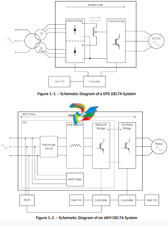
1.4.1 DFE Network Bridge
A DFE network bridge comprises of one or more diode rectifier modules, plus ancillary components, which
could include:
• Line reactor;
• Fusing;
• Pre-charge circuit;
• Interbridge transformer;
• D.C. Link inductor.
The network bridge converts the a.c. supply to an unsmoothed d.c. voltage. Power flow is from the network
supply only.
Harmonic currents produced in the supply system by variable speed drives with uncontrolled rectifier inputs
may be reduced by changing from 6 pulse to 12 pulse (6 phase) input.
In the case of a 12 pulse input:
• A phase shifting transformer is used to produce the additional 3 phases which are phase
shifted by 30° as shown in Figure 1–1. These two sets of three phase supplies are rectified by
two rectifier bridges.
• Instantaneous voltage differences, between the outputs of the two rectifiers, are absorbed by
an interbridge transformer connected between the two positive outputs of the rectifiers. The
output to the d.c. link is taken from the centre-tap of the interbridge transformer.
1.4.2 Sinusoidal Front End (AEM Network Bridge)
The network bridge of an AEM drive comprises of one to six DELTA transistor modules. The network bridge
is combined with the following ancillary components to form a Sinusoidal Front End (SFE):
• Line reactor;
• Fusing;
• PWM filter;
• MVM unit;
• Sharing reactors;
• MV3000e Controller.
The SFE bridge can be used to convert the a.c. supply to a d.c. voltage, but also has the capability to allow
regeneration of energy back into the network, and as such is required for power generation applications
(e.g. wind turbines).
The AEM network bridge provides a very clean voltage waveform, but the harmonic content will require
filtering.
1.4.3 Machine Bridge
The machine bridge converts between a d.c. and an a.c. voltage of variable frequency and amplitude.
Generally in a DFE system, the power flows from the d.c. link, out into the a.c. load. In an AEM system, power
flow is bi-directional.
The machine bridge comprises of one to six DELTA transistor modules and the following ancillary
components:
• Sharing reactors;
• Fusing;
• MV3000e Controller.
2.7.1 Electrical Connections
The connections from the SMPS unit to other equipment in the DELTA drive are as follows:
• One 40 way ribbon cable, supplied as part of the DELTA transistor module;
• A two pin connector plugs into the d.c. link of the associated DELTA transistor module.
2.8 MV3000E DRIVE DATA MANAGERTM (KEYPAD)
Units covered: MVS3000-4001 (DDM)
MVS3001-4001 (Installation kit)
The Drive Data ManagerTM, shown in Figure 2–6, is an ergonomically designed keypad which provides the
functionality to configure a drive system. It also provides motor control and diagnostic functions.
The Drive Data ManagerTM derives its power supply from the MV3000e Controller

An installation kit containing a waterproof gasket and a lead is available separately. The lead for
connection from the Keypad to the MV3000e controller has a maximum length of 3 m (9.8 ft.). This lead
length determines the relative positions of the Drive Data ManagerTM and the controller. When supplied
with a waterproof gasket, it can be mounted on an enclosure door to meet IP 65 enclosure protection.
The specification for the Drive Data ManagerTM and its electrical connections, are included in the T1915
Instruction Sheet which is supplied with the Drive Data ManagerTM.
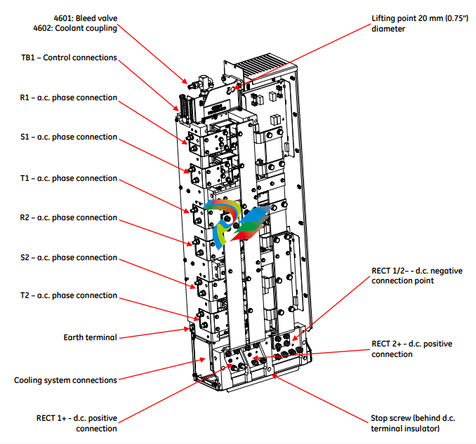
2.9 DELTA RECTIFIER MODULE
Unit covered: MVRL2100-4601.
MVRL2100-4602.
In a DELTA drive system, rectifier modules shown in Figure 2–7, are used in network bridges to convert an
a.c. supply into a rectified, unsmoothed d.c. supply.
The rectifier module is available in a single rating. Larger rectifier power ratings can be achieved by
connecting the modules in parallel (derating will be necessary, see Section 2.9.4.1: Parallel Ratings).
Each module has a pair of three-phase, six pulse rectifiers, with individual a.c. input terminals. Two d.c.
positive terminals and a single d.c. negative output terminal are provided.
The rectifier module may be operated as a 12-pulse network bridge. This configuration is achieved by
connecting the d.c. positive outputs together through an interbridge transformer and one a.c. input being
phase-shifted in relation to the other by an external supply transformer.
-
 Beckhoff C6640-0040 Control Cabinet Industrial PC 7-Slot
 -
 BECKHOFF CONTROL CABINET INDUSTRIAL PC - C6930-1062-0050
 -
 Beckhoff Automation EtherCAT Terminal EK1100 EK1122
 -
 Beckhoff CP6533-0001-0060 IPC
 -
 Beckhoff EK9500 | EtherNet/IP™ Bus Coupler
 -
 Beckhoff CP6202-1047-0050 - An industrial-grade embedded panel computer.
 -
 Beckhoff C6650-0040 Industrial PC
 -
 BECKHOFF CX5230-0185 / 000119805 PLC Module
 -
 BECKHOFF EL4732 | EtherCAT Terminal, 2-channel analog output, voltage, ±10 V, 16 bit, oversampling
 -
 Beckhoff CP6202-0001-0010 Economy Built-In Panel
 -
 Beckhoff AX5206-0000-0202 Digital Compact Servo Drives 2-channel
 -
 Beckhoff CP6606-0001-0020 7-inch Economy Panel PC
 -
 Beckhoff CPU basic module CX2020-0155 + power supply module CX2100-0004
 -
 Beckhoff CP2913-000 Multi-Touch Display
 -
 Beckhoff CP6500-1012-0060 14250369 Control Cabinet
 -
 Beckhoff CP7902-0001-0000 Economy Control Panel with DVI/USB Extended interface
 -
 Beckhoff C6920-0010 Control cabinet Industrial PC
 -
 BECKHOFF C3640-0050 Build-in Industrial PCs
 -
 Beckhoff KL6023-0000 KL6023 EnOcean Wireless-Adapter
 -
 Kollmorgen AKM54G-ANC2DB00 servo motor
 -
 Kollmorgen AKD-P00606-NBCN-0000 Servo Drive
 -
Kollmorgen S200 Series S20350-VTS SERVO DRIVE
-
 KOLLMORGEN AKD-P00606-NBCC-I000 SERVO DRIVE
 -
 Kollmorgen MV65WKS-CE310/22PB Servo Drive Control Module
 -
 Kollmorgen S20360-VTS-021 Servo Drive
 -
 KOLLMORGEN CR06550 High-precision digital servo amplifier
 -
 KOLLMORGEN DBL5N01050-03S-VV0-S40 3-Phase AC Synchronous Brushless Servo Motor
 -
 KOLLMORGEN S70301-NANANA-024 SERVO DRIVE
 -
 Kollmorgen S20360-VTS S200 Series Servo Drive
 -
 Kollmorgen RBE-03011-A00 Brushless Frameless Servo Motor
 -
 KOLLMORGEN AKD-T00306-NBAN-0000 INPUT SERVO DRIVE
 -
 KOLLMORGEN S700 Servo Controller S70302-NANANA
 -
 Kollmorgen AKD-P00607-NBEC-0000 400/480VAC 4.40KVA Servo Drive.
 -
 KOLLMORGEN S70102-NANANA SERVO DRIVE
 -
 KOLLMORGEN AKM21E-ANSNEH02 PM Servo Motor & PRD-AMPE25EB-00 Servo Drive Array
 -
 KollMorgen SC1R06260 Servo Drive 1.4/2.2 KVA 115230 Vac
 -
 Kollmorgen AKD-P00306-NBAN-0000 Servo Drive
 -
Kollmorgen TTB2-2042-3052-A DC Motor Industrial Drive 5.5A 185 oz/in
-
 KOLLMORGEN SERVOSTAR 610-AS SERVO AMPLIFIER_SERVOSTAR610AS_S61001
 -
 KOLLMORGEN PRD-0016400P-10 & PRD-0016600D-30 Axis Control System Modules
 -
KOLLMORGEN Seidel DBL5N01700-03S-000-S40 Servo Motor
-
 Hirschmann RS20-1600M2T1SDAEHH03.1.02 Rail Switch
 -
 Hirschmann BRS30-24TX Industrial Rail Switch
 -
 Hirschmann RSPM20-4T14T1EV9HHS999.9.99 Managed Ethernet Switch
 -
 Hirschmann BELDEN RS40-0009CCCCSDAPHH09.0.14 / RS400009CCCCSDAPHH09014
 -
Hirschmann RS40 Rail Switch RS40-0009CCCCSDAE
-
 Hirschmann BELDEN RS30-0802T1T1SDAP / RS300802T1T1SDAP Fully Managed Layer 2 Compact Rail Switch
 -
 Hirschmann BELDEN RS20-0800M2M2SDAUHH / RS200800M2M2SDAUHH
 -
 Hirschmann EAGLE30-04022O6TT999SCCY9HSE3F Industrial Firewall Router Switch
 -
 Hirschmann RS20-1600T1T1SDAEHH09.0.14 RS20 Rail Mount Ethernet Switch
 -
 Hirschmann EAGLE0200T1T1TDDY90000HHE05.3.03 Industrial Security Router
 -
Hirschmann - BELDEN MIPP-AD-1L9P
-
 HIRSCHMANN RSPM20-4Z64Z6TV9HHS9 942 106-999 RAIL SAFETY SWITCH
 -
 HIRSCHMANN FIBEROPTIC MODULE FIP P/N: OZDFIPG3T
 -
 HIRSCHMANN RS20-1600M2M2SDAUHH Ethernet rack-mounted switch
 -
 HIRSCHMANN BELDEN RS20-0400T1T1SDAEHH04.0.01 / RS200400T1T1SDAEHH04001
 -
HIRSCHMANN MM2-4FXM3 MICE Media Module
-
HIRSCHMANN RS20-0800M2M2SDAE Industrial Ethernet Rail Switch
-
 Hirschmann RS20-2400T1T1SDAP / RS20-2400T1T1SDAPHH05.0.02
 -
 GE MLJ1005B010H00C MLJ Digital Synchromism Check
 -
 ALSTOM MICROTECH DX21-M2 Digital Excitation Controller
 -
HIRSCHMANN BRS20-1200ZZZZ-STCY99HHSES
-
 HIRSCHMANN MM3-4FXM2 MICE Media Module
 -
Hirschmann RSB20-0800T1T1SAABHH 8Port ENet Rail Switch RSB20
-
 Hirschmann MACH102-8TP Ethernet Switch
 -
 SAACKE DDZ-M marine steam pressure atomizer
 -
 SAACKE SKV-A marine rotary cup atomizer
 -
 SAACKE Seavis HMI05e
 -
 Kollmorgen MMC-SD-2.0-230 Servo Drive 100-240VAC 2KW 10A Output 3PH 100-240VAC
 -
 Kollmorgen Servo drive CR10550
 -
 Kollmorgen AKD-P01207-NACN-0054 Servo Driver
 -
 Kollmorgen S406M-CA-036 Servostar
 -
.png) Kollmorgen AKD-B02407-NAAN-0000 Digital Servo Drive
Kollmorgen AKD-B02407-NAAN-0000 Digital Servo Drive -
 Kollmorgen SERVOSTAR S406AM-CA Digital Servo Drive
 -
 KOLLMORGEN SERVOSTAR 603-AS SERVO AMPLIFIER_SERVOSTAR603AS_S60301
 -
Kollmorgen S700 Servo Controller (S70602-NANANA-NA)
-
 Kollmorgen MPK411 controller
 -
 KOLLMORGEN MMC-SD-1.3-460-D Smart Drive
 -
 KOLLMORGEN AKM21C-CKB2AA-00 / AKM21CCKB2AA00 Servomotor
 -
 BECKHOFF AX5106-0000-0200 | Digital Compact Servo Drives 1-channel
 -
 BECKHOFF C3620-0000 INDUSTRIAL COMPUTER (MOTORSHELVES)
 -
 Beckhoff EK1960-0000 TwinSAFE Compact Controller
 -
 Beckhoff C6930-0050 Control Cabinet Industrial PC
 -
 Beckhoff CP7711-0001-0030 Industrial Computer Detection
 -
 Beckhoff CX1001-0111 Embedded PC CPU Module
 -
 Beckhoff C6017-0020 | Ultra-compact Industrial PC
 -
 Beckhoff EK1322 | 2-port EtherCAT P junction with feed-in
 -
 Beckhoff CP2219-0010 Panel
 -
 BECKHOFF C6015-0020 ULTRA COMPACT INDUSTRIAL PC
 -
 BECKHOFF CX2030-0120/Standard CPU Module Embedded PC Windows PLC controller
 -
 Beckhoff CP7721-1090-0020 Panel PC
 -
 Beckhoff PC CPU Module CX5130-0175
 -
 Beckhoff C6920-0050 Control Cabinet
 -
 Beckhoff EL6631 EtherCAT 2-Port Communication Interface, Profinet RT Controller
 -
 Beckhoff CP6202-0001-0060 touch screen panel PC
 -
 Beckhoff CP3916-1002-0000 Multi-Touch Control Panel
 -
 Beckhoff EP1809-0021 | EtherCAT Box, 16-channel digital input, 24 V DC, 3 ms, M8Preferred type
 -
 Beckhoff CX8190 PLC Embedded Industrial PC Ethernet Controller
 -
 Beckhoff CX2100-0914 Power Supply for External
 -
 Beckhoff Automation CP6906-0001-0000 HMI
 -
 Beckhoff EP7342-0002 Module
 -
 Beckhoff CX1020-0112 / CX1100-0910 / CX1020-N010 / CX1100-0003 Windows CPU
 -
 Beckhoff EP7211-0034 EtherCAT Box 1 Channel Motion Interface
 -
 Beckhoff C6240-0030 Control cabinet Industrial PC
 -
 beckhoff motherboard CB1052-0004 CB1052-0004
 -
 Beckhoff AX2006-AS Servo Drive / Variable Frequency Drive
 -
BECKHOFF CP6207-0001-0020 NSMP
-
 Beckhoff C6930-1142-0060 Industrial Computer
 -
 Beckhoff FC7501-0000 interface card
 -
 Beckhoff CX5140-0175 Embedded PC PLC CPU CX5140 Industrial Controller
 -
 Beckhoff CP7802-1100-0010: High-End IP65 Control Panel with DVI/USB Extended Interface
 -
BECKHOFF CP3716-1058-0010 CONTROL PANEL
-
 Beckhoff AX8108-0000 Single-Axis Module
 -
 Beckhoff CU8851-0000 | USB extension, USB Extended 2.0 receiver box
 -
Beckhoff C6017-0030 | Ultra-compact Industrial PC
-
 Beckhoff CX1001-0120/CX10010120.cx1000-n001.cx1000-n000 System Overview
 -
 Beckhoff CPU Module CX5140-0155/4GB CPU Module
 -
 Beckhoff CP6533-0001-005: Built-in Panel PC with High-Definition Multi-Touch Control
 -
 Beckhoff EL5042 | EtherCAT Terminal, 2-channel encoder interface, BiSS® C
 -
 Beckhoff C6920-1080-0040: Premium Control Cabinet Industrial PC
 -
 Beckhoff C6920-0060 | Control cabinet Industrial PC
 -
 Beckhoff Embedded-PC CX5010-1121
 -
 Beckhoff CB3050-0010 Mainboard Motherboard
 -
 Beckhoff PLC module CX1020-0000 Basic CPU module (service phase)
 -
 Beckhoff CP7812-1056-0010 15" Multitouch Display Control Panel
 -
 Beckhoff CX5120-0115 /2GB Controller Module
 -
 Beckhoff CP7201-1000-0000 Industrial Panel PC
 -
 Beckhoff Servo Motor AM8061-0JH1-0000


