
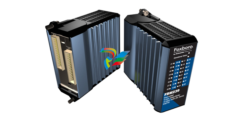
Foxboro FBM239, Discrete 16DI/16DO Module
FBM239, Discrete 16DI/16DO Module
The FBM239 contains 16 discrete input and 16 discrete output channels that are compatible with voltages
and currents commonly found in industrial plants. An external power supply is used to energize the field
circuits.
OVERVIEW
The FBM239 Discrete 16DI/16DO Module provides
16 digital inputs with sixteen digital output channels.
Associated Termination Assemblies (TAs) and
Termination Assembly Adapters (TAAs) provide for
discrete nominal inputs of 30 V dc, 60 V dc,
120 Vac/125 V dc or 240 Vac and nominal outputs
of 60 V dc, 120 V ac/125 V dc or 240 V ac. The
module performs signal conversion required to
interface the electrical input signals from the field
sensors to the Module Fieldbus.
Depending on the type of I/O signal required, the TAs
or TAAs support current limiting devices, high voltage
attenuation circuits, optical isolation and external
power source connections.
When connected to the appropriate Termination
Assembly Adapters (TAAs) or TAs, the FBM239
module provides functionality formerly provided by
the 100 Series FBM I/O subsystem. TAAs and TAs
are available which support the functionality of the
main FBM09. FBM10. FBM11. FBM26 and FBM41
(8 input/ 8 output main FBMs). These main FBMs
may be used with expansion FBM14. FBM15.
FBM16. FBM27 or FBM42 (8 input/8/output
expansion FBMs).
FEATURES
Key features of the FBM239 are:
Sixteen digital input channels, used for either
contact sensing, or DC voltage monitoring
Sixteen digital output channels, used for either
DC output switching with an external source (e.g.
to control powering of various external loads), or
DC output switching with an internal source only
(e.g. to power external solid state relays or other
similar devices)
Rugged design suitable for enclosure in Class G3
(harsh) environments
Supports discrete input signals at voltages of:
• 30Vdc/60 Vdc
• 120Vac/125 V dc
• 240V AC
Supports output switching at voltages of:
• 60 V DC
• 120 V AC/125 V DC
• 240 V AC
Executes the programs for Digital I/O (ECB5), and
Ladder Logic (ECB8)
Various Termination Assemblies (TAs) provide for
per-channel isolation and 100 Series I/O
upgrade, and contain:
• High voltage attenuation and optical isolation
for inputs
• External power connection for device
excitation
• Output current limiting.
STANDARD DESIGN
FBM239 has a rugged extruded aluminum exterior
for physical protection of the circuits. Enclosures
specially designed for mounting the FBMs provide
various levels of environmental protection, up to
harsh environments, per ISA Standard S71.04.
VISUAL INDICATORS
Light-emitting diodes (LEDs) incorporated into the
front of the module provide visual indication of the
Fieldbus Module operational status, as well as the
discrete states of the individual input/output points.
EASY REMOVAL/REPLACEMENT
The module can be removed/replaced without
removing field device termination cabling, power, or
communication cabling.
FIELDBUS COMMUNICATION
A Fieldbus Communications Module or a Control
Processor interfaces to the 2 Mbps module Fieldbus
used by the FBMs. The FBM239 accepts
communication from either path (A or B) of the 2
Mbps Fieldbus —should one path fail or be switched
at the system level, the module continues
communication over the active path.
MODULAR BASEPLATE MOUNTING
The module mounts on a DIN rail mounted
baseplate, which accommodates up to four or eight
Fieldbus Modules. The Modular baseplate is either
DIN rail mounted or rack mounted, and includes
signal connectors for redundant Fieldbus, redundant
independent DC power, and termination cables.
FIELD I/O SIGNALS
Field I/O signals connect to the FBM subsystem via
DIN rail mounted TAs or Termination Assembly
Adapters (TAAs) mounted on the conversion
mounting structures. TAAs are discussed in
Termination Assembly Adapter Modules for
100 Series Upgrade (PSS 31H-2W4). The TAs used
with the FBM239 are described in “TERMINATION
ASSEMBLIES AND CABLES” on page 7.
FUNCTIONAL SPECIFICATIONS
Input/Output Channels
16 group isolated digital input channels and 16 group
isolated digital output channels
Filter/Debounce Time
Configurable (No Filtering, 4. 8. 16 or 32 ms)
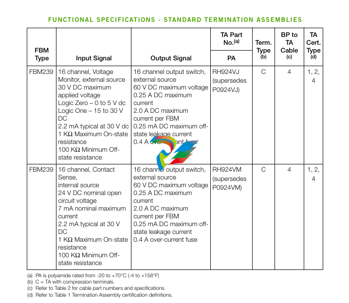
Voltage Monitor (FBM239 with feed through TA
RH924VJ (supersedes P0924VJ))
INPUT
30 V DC maximum applied voltage
ON-STATE VOLTAGE
15 to 30 V DC
OFF-STATE VOLTAGE
0 to 5 V DC
CURRENT INPUT FOR ON-STATE
2.3 mA maximum at 30 V DC
SOURCE RESISTANCE LIMITS
ON-STATE
1 k Ω (maximum) at 15 V dc
OFF-STATE
100 k Ω (minimum) at 30 V dc
Contact Sense (FBM239 with feed through TA
RH924VM (supersedes P0924VM))
CONTACT SUPPLY
24 V DC nominal (supplied by FBM through the
TA)
CONTACT CURRENT
1.8 mA DC nominal
Output (FBM239 with feed through TAs
RH924VJ (supersedes P0924VJ) or RH924VM
(supersedes P0924VM))
APPLIED VOLTAGE (EXTERNAL)
60 V dc maximum
LOAD CURRENT
0.24 A DC maximum per channel
2.0 A DC maximum per TA
INDUCTIVE LOADS
Outputs ma
FUNCTIONAL SPECIFICATIONS (CONTINUED)
Power Requirements
INPUT VOLTAGE RANGE
24 V dc +5%, -10%
MODULE CONSUMPTION
2.65 Operating
TEMPERATURE-20 to + 70°C (-4 to +158°F)
RELATIVE HUMIDITY
5 to 95% (noncondensing)
ALTITUDE-300 to +3.000 m (-1.000 to +10.000 ft)
Storage
TEMPERATURE-40 to +70°C (-40 to +158°F)
RELATIVE HUMIDITY
5 to 95% (noncondensing)
ALTITUDE-300 to +12.000 m (-1.000 to +40.000 ft)
Contamination
Suitable for use in Class G3 (Harsh) environments as
defined in ISA Standard S71.04. based on exposure
testing according to EIA Standard 364-65. Class III.
Vibration
0.75 m/S2 (0.75g) from 5 to 500 Hz
Mounting
MODULE
FBM239 mounts on a baseplate. The baseplate
can be mounted on a DIN rail (horizontally or
vertically), or horizontally on a 19-inch rack using
a mounting kit. Alternatively, FBM239 mounts on
a 100 Series conversion mounting structure.
Refer to Standard 200 Series Baseplates
(PSS 31H-2SBASPLT) or 100 Series Conversion
Mounting Structures (PSS 31H-2W8) for details.
TERMINATION ASSEMBLY
The TA mounts on a DIN rail and accommodates
multiple DIN rail styles including 32 mm (1.26 in)
and 35 mm 1.38 in)
Weight
MODULE
284 g (10 oz) approximate
TERMINATION ASSEMBLY - COMPRESSION
Dimensions - Module
HEIGHT
102 mm (4 in),114 mm (4.5 in) including mounting
lugs
WIDTH
45 mm (1.75 in)
DEPTH
104 mm (4.11 in)
Dimensions - Termination Assembly
Compression Screw - Refer to page 26
Part Numbers
FBM239 MODULE
RH927AG (supersedes P0927AG)
TERMINATION ASSEMBLIES
Refer to “FUNCTIONAL SPECIFICATIONS -
Standard TERMINATION ASSEMBLIES” on
page 8. “FUNCTIONAL SPECIFICATIONS - Main
TERMINATION ASSEMBLIES” on page 9 and
“FUNCTIONAL SPECIFICATIONS - Expansion
TERMINATION ASSEMBLIES” on page 15.
Termination Cables
CABLE LENGTHS
Up to 30 m (98 ft)
CABLE MATERIALS
Polyurethane or Low Smoke Zero Halogen
(LSZH)
TERMINATION CABLE TYPE
Baseplate to Main TA
Type 4 - Refer to Table 2
Main TA to Expansion TA
Type 6 - Refer to Table 3
BASEPLATE TO MAIN TA CABLE CONNECTION
FBM Baseplate End
37-pin D-subminiature
Termination Assembly End
37-pin D-subminiature
MAIN TA TO EXPANSION TA CABLE
CONNECTION
Main TA End
25-pin D-subminiature
Expansion TA End
37-pin D-subminiature
Construction - Termination Assembly
MATERIAL
Polyamide (PA), compression
Field Termination Connections
COMPRESSION - ACCEPTED WIRING SIZES
Solid/Stranded/AWG
0.2 to 4 mm2/0.2 to 2.5 mm2/24 to 12 AWG
Stranded with Ferrules
0.2 to 2.5 mm2 with or without plastic collar
TERMINATION ASSEMBLIES AND CABLES
General Description
Field I/O signals connect to the FBM subsystem via
DIN rail mounted termination assemblies (TAs).
Multiple types of TAs are available with FBM239 to
provide I/O signal connections, signal conditioning,
optical isolation from signal surges, and external
power connections for field devices as required by
the particular FBM. Since these features are built into
the termination assemblies (where required), in most
applications there is no need for additional
termination equipment for field circuit functions such
as circuit protection or signal conditioning (including
fusing and power distribution).
The DIN rail mounted termination assemblies
connect to the FBM subsystem baseplate by means
of removable termination cables. The cables are
available in a variety of lengths, up to 30 meters
(98 feet), allowing the termination assemblies to be
mounted in either the enclosure or in an adjacent
enclosure. Refer to “Cable Types and Part Numbers”
on page 22 and “Cable Types (Main TA to Expansion
TA Cables) and Part Numbers” on page 23 for
termination cable part numbers and specifications.
Use of Termination Assemblies in 100 Series
Upgrade
When an FBM239 is used to replace 100 Series
FBMs, its associated termination assembly is
determined based on which 100 Series FBM is being
replaced. Typically, the 100 Series FBM being
replaced is a main FBM and may be used in
conjunction with an expansion FBM.
A single FBM239 provides the I/O communications
for both the 100 Series equivalent main and
expansion TAs. To provide enough terminals for the
field I/O wiring, two termination assemblies are used
with the FBM239 - one for the field I/O wiring for the
replaced main FBM, and one for the field I/O wiring
for the replaced expansion FBM.
The “expansion” termination assembly is daisy
chained to the “main” termination assembly via the
expansion cables listed in Table 3 on page 25.
The table “FUNCTIONAL SPECIFICATIONS - Main
TERMINATION ASSEMBLIES” on page 9 lists the
termination assemblies needed to replace the
100 Series main FBMs. “FUNCTIONAL
SPECIFICATIONS - Expansion TERMINATION
ASSEMBLIES” on page 15 lists the termination
assemblies needed to replace the 100 Series
expansion FBMs.
Alternatively, the FBM239 can accept field wiring
through a Termination Assembly Adapter (TAA)
instead of the termination assemblies when replacing
100 Series FBMs. This is discussed in Termination
Assembly Adapter Modules for 100 Series Upgrade
(PSS 31H-2W4).
Discrete Inpu
-
 HIRSCHMANN RS20-0400M2T1SDAPHC08.0.01 Managed Switch
 -
 MACH1130 Hirschmann Industrial Switch
 -
 HIRSCHMANN 943824-002 SPIDER 5TX Industrial Ethernet Switch
 -
 HIRSCHMANN RS30-0802O6O6SDAEHC09.1.00 Managed Industrial Switch
 -
 HIRSCHMANN RS20-0400M2M2TDAEHC04.0.01 Industrial Switch
 -
 HIRSCHMANN BRS20-0600Z6Z6-STCZ99HHSES Industrial Switch
 -
 HIRSCHMANN MACH104-20TX-FR-L3P Industrial Ethernet Switch
 -
 HIRSCHMANN RS40-0009CCCCEDBPHH06.0.01 Industrial Switch
 -
 HIRSCHMANN RS2-3TX/2FX EEC Industrial Ethernet Switch
 -
 Hirschmann MACH 1020/1030 Fast/Gigabit Rack Mount Switches
 -
 HIRSCHMANN RS20-0800M2M2SDAPHC09.0.14 Industrial Switch
 -
 HIRSCHMANN RS20-1600T1T1SDAEHC09.0.04 Industrial Switch
 -
 HIRSCHMANN RSB20-0800T1T1EAABHH Industrial Switch
 -
 HIRSCHMANN MACH4002-48+4G-L3E Industrial Backbone Switch
 -
 HIRSCHMANN RS20-0400S2T1SDAE Industrial Managed Switch
 -
 HIRSCHMANN RS20-0800S2T1SDAUHC Industrial Switch
 -
 HIRSCHMANN RS20-2400S4S4SDAEHC09.0.14 industrial switch
 -
 HIRSCHMANN OS20-001200T5T5T5- TBBZ999HHNE3S 08.1.00 industrial switch
 -
HIRSCHMANN OS20-001200T5T5T5- TBBZ999HHNE3S 08.1.00 industrial switch
-
 HIRSCHMANN RS40-0009CCCCSDAEHH09.0.14 switch
 -
 Hirschmann RS20-1600T1T1SDAUHC Management-type Ethernet Switch
 -
 Hirschmann M1-8SFP Switche
 -
Hirschmann Industrial Ethernet Ruggedized Switch MACH1000 Family
-
 Basler Electric, Solid State Protective Relay, BE1-60
 -
BASLER ELECTRIC SR4A-2B15B3A Static Voltage Regulator
-
.png) BASLER ELECTRIC EXCITER DIODE MONITOR EDM-200
BASLER ELECTRIC EXCITER DIODE MONITOR EDM-200 -
.png) BASLER ELECTRIC DECS125-15-B2C5 DIGITAL EXCITATION CONTROL SYSTEM V 2.0.9
BASLER ELECTRIC DECS125-15-B2C5 DIGITAL EXCITATION CONTROL SYSTEM V 2.0.9 -
 BASLER ELECTRIC BE1-851 OVERCURRENT PROTECTION RELAY MECHANISM
 -
 Basler Electric BE1-51A / BE151A
 -
 Basler Electric BE1-40Q Loss of Excitation Relay
 -
 Basler Electric BE1-87G Variable Percentage Differential Relay
 -
 Basler Electric BE1-11 Protection System I5A3M2P2N0EA00
 -
 BASLER ELECTRIC DECS-200-1C Digital Excitation Control System
 -
 Basler Electric / Kohler BE1-11g Generator Protection Relay G5A3M2J2N0E000
 -
BASLER ELECTRIC DECS125-15 DIGITAL EXCITATION CONTROL SYSTEM
-
 BASLER ELECTRIC BE1-951 OverCurrent Protecton System
 -
Basler Electric DECS-200-1L Digital Excitation Control System
-
 Basler Electric DGC-2020HD-5NS1DNSBA Digital Genset Controller -
 -
 BASLER ELECTRIC BE1-81T1EE1WA0N1F / BE181T1EE1WA0N1F
 -
 BASLER ELECTRIC BE1-25M1EA6PN5R1F / BE125M1EA6PN5R1F
 -
 BASLER ELECTRIC DECS-250-LN1SN1N DIGITAL EXCITATION CONTROL SYSTEM
 -
Basler Electric DECS-250-CN2CN 1N Digital Excitation Control System Unit
-
 BASLER ELECTRIC DECS-300-C0N0 DIGITAL EXCITATION CONTROL SYSTEM
 -
 BASLER ELECTRIC BE1-87T-A1E-A1J-D0S1F / BE187TA1EA1JD0S1F
 -
BASLER ELECTRIC BE1-11-G6D1M0J2P0E000 Protection System
-
 BASLER ELECTRIC BE1-GPS100-E4N1H1N GENERATOR PROTECTION SYSTEM
 -
 Jaquet Relay card (Auxiliary module) FTV 3090 377Z-03985
 -
 Jaquet Trip Chain Control card FTBU 3034 377Z-05030
 -
 Jaquet with input card -E04 FTFU 3024 -E04 377Z-05855
 -
 Jaquet with input card -E03 FTFU 3024- E03 377Z-03983
 -
 Jaquet FTFU 3024- E02 377Z-03982 with input card -E02
 -
 Jaquet FTFU 3024-E01 377Z-03981 with input card -E01
 -
 Hirschmann RS20-2400T1T1SDAE Industrial Managed Ethernet Switch
 -
 Hirschmann BELDEN EAGLE30-04022O6TT999SCCV9HSE3F
 -
 Hirschmann MM3-2FXS2/2TX MICE Media Module
 -
 Hirschmann RS20-1600M2M2SDAPHC08.0.05 Industrial Managed Switch
 -
 Hirschmann OZD Profi 12M G12-1300 PRO Fieldbus Repeater
 -
 Hirschmann SPIDER 4TX/1FX-ST EEC Industrial Ethernet Switch
 -
 Hirschmann MM2-2FXM3/2TX1 MICE Media Module
 -
 Hirschmann RS20-2400M2M2SDAPHC09.0.14 Industrial Switch
 -
 Hirschmann RS20-0400M2M2SDAEHC07.1.05 OpenRail Switch
 -
 Hirschmann OZD Profi 12M G12-EEC Fieldbus Repeater
 -
 HIRSCHMANN MDA422-1/2-3.5c-23/46 sensor
 -
Hirschmann RS30-2402T1T1SDAUHC Managed Industrial Switch
-
 Hirschmann OZD GENIUS G12 Industrial Switche
 -
 Hirschmann OZD 485 G12-1300 PRO Fieldbus Repeater
 -
 Hirschmann MM2-2FXM2 MICE Media Module
 -
 Hirschmann RS20-1600S2T1SDAUHC Managed Industrial Switch
 -
 Hirschmann MS20-0800SAAEHH04.2.04 MICE Switch
 -
 Hirschmann SPIDER 4TX/1FX EEC Unmanaged Industrial Switch
 -
 HIRSCHMANN MS4128-L3P EEC Managed Industrial Ethernet Switch
 -
 HIRSCHMANN RS20-0400M2T1SDAPHC08.0.01 Managed Switch
 -
 ETEL EA-S0M-400-40/80A-0000-00 AccurET Modular Power Supply
 -
 ETEL EA-B0I-0-0-0000-00 Backplane Interface Board
 -
 ETEL EA-P2M-400-15/40A-0100-00 Position Controller
 -
ETEL EA-P2M-400-15/40A-0000-00 Position Controller
-
 ETEL EA-P2M-400-10/20A-0100-01 Position Controller
 -
 ETEL EA-P2M-400-10/20A-0000-01 Position Controller
 -
 ETEL EA-P2M-400-5/10A-0100-01 Position Controller
 -
 ETEL EA-P2M-048-2.5/5A-0000-01 Modular Position Controller
 -
 ETEL EA-S0M-300-40/80A-0000-00 Power Supply Module
 -
 ETEL EA-P2M-300-07/15A-0100-01 Position Controller
 -
 ETEL EA-P2M-300-07/15A-0000-01: Modular Position Controller
 -
 ETEL EA-P2M-300-4/7.5A-0100-01 Overview
 -
 Basler Electric MOC2. Motor Operated Potentiometer
 -
 Basler Electric BE1-11 RTD Module, Resistance Temperature Detector
 -
 Basler Electric RDP-110C, Remote Display Panel
 -
 Basler Electric VRM-2020. Voltage Regulation Module
 -
 Basler Electric IDP-1500. Interactive Display Panel
 -
 Basler Electric AEM-2020. Analog Expansion Module
 -
 Basler Electric IDP-2020. Interactive Display Panel
 -
 Basler Electric CEM-2020. Contact Expansion Module
 -
 Basler Electric CEM-125. Contact Expansion Module
 -
 Basler Electric BE2000E, Digital Voltage Regulator
 -
 Basler Electric SMC-150. Synchronous Motor Controller
 -
 Basler Electric AVC125-10. Voltage Regulator
 -
 Basler Electric BE1-25. Sync-Check Relay
 -
 Basler Electric DGC-2020ES, Digital Genset Controller
 -
 ETEL EA-P2M-400-5/10A-0000-01 Position Controller
 -
 Basler Electric BE1-64F, Ground Fault Relay
 -
 Basler Electric BE1-79M, Multi Shot Reclosing Relay
 -
 Basler Electric BE1-81O/U, Digital Frequency Relay
 -
 Basler Electric BE1-87B, High Impedance Bus Differential Relay
 -
 Basler Electric BE1-79A, Reclosing Relay
 -
 Basler Electric BE1-27. BE1-59. BE1-27/59. Voltage Relay
 -
 Basler Electric SMC-250. Synchronous Motor Controller
 -
 Basler Electric SGC-250N, Synchronous Generator Controller
 -
 Basler Electric SGC-250. Synchronous Generator Controller
 -
 Basler Electric BE1-50/51 Plug and Play and Retrofit Relays
 -
 Basler Electric DECS-2100. Digital Excitation Control System
 -
 Basler Electric DECS-250E, Digital Excitation Control System
 -
 Basler Electric BE1-700V, Voltage Only Digital Protective Relay
 -
 Basler Electric DECS-250. Digital Excitation Control System
 -
 Basler Electric DECS-450. Digital Excitation Control System
 -
 Basler Electric DECS-150. Digital Excitation Control System
 -
 Basler Electric ES-49. Temperature Relay
 -
 Basler Electric ES-81O/U, ES-81O,ES-81U Overfrequency Relay
 -
Basler Electric ES-74V, DC Voltage Sensing Relay
-
Basler Electric ES-27/59. Under/Overvoltage Relay
-
 Basler Electric ES-27. Undervoltage Relay
 -
 Basler Electric ES-25. Sync-Check Relay
 -
 Basler Electric ES-47, ES-47N Phase Sequence Relay
 -
Basler Electric ES-37.ES-37/51 Undercurrent Relay
-
 Basler Electric ES-32. Reverse Power Relay
 -
Basler Electric ES-59. Overvoltage Relay
-
 Basler Electric ES-55. Power Factor Relay
 -
 Basler Electric DGC-2020HD, Digital Genset Controller
 -
 Basler Electric BE1-FLEX, Protection, Automation, and Control System


