
schneiderIGP10, IGP20 Intelligent Gauge Pressure Transmitters IAP10 Intelligent Absolute Pressure Transmitter
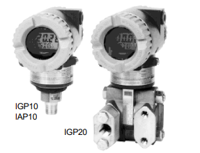
• IGP10 for compact light weight and direct-to-process
mounting (bracket optionally available)
• IGP20, bracket mounted, for lower ranges, more
material options, and vacuum service
• Field-proven silicon strain gauge technology
• Corrosion-resistant epoxy finish
• Accuracy to ± 0.07 % of span
• Ambient temperature effects to ± 0.2 % URL
per 55 °C (100 °F) change
• Intelligent FOXCOM & HART / 4 to 20 mA version
or economical 4 to 20 mA version
• LCD Indicator / Pushbutton Configurator
to set zero, span, display units, etc.
Optional on Digital / 4 to 20 mA version,
Standard on 4 to 20 mA version
These Intelligent, two-wire transmitters provide precise, reliable, measurement of gauge or absolute
pressure, and transmit a 4 to 20 mA output signal
with a superimposed HART/ FOXCOM digital signal for remote configuration and monitoring.
Accuracy (Includes Linearity, Hystersis, and
Repeatability)
Electronics
Version
Configured
Output Signal
Accuracy in %
of Calib. Span
-D & -T Digital
4 to 20 mA
± 0.07
± 0.1
-I 4 to 20 mA ± 0.2
Model Codes IGP10
Ambient Temperature Effect
Total effect for a 55 °C (100 °F) change within Normal Operating Conditions limit is:
Electronics -D, -T: ± 0.2 % of URL
Electronics -I: ± (0.2 % of URL + 0.1 % of span)
For complete specifications, refer to Product Specification
Sheet PSS 2A-1C13 B
Intelligent Direct Connected Gauge Pressure Transmitter IGP10
Electronics Versions and Output Signal
Intelligent; Digital FoxCom and/or 4 to 20 mA dc, Configurable . . . . . . . . . . . . . . -D
Intelligent; Digital HART and 4 to 20 mA . . . . . . . . . . . . . . . . . . . . . . . . . -T
4 to 20 mA Analog Output, Explosionproof and Intrinsically Safe . . . . . . . . . . . . . -I
Structure Code - Process Connection, Sensor, and Fill Fluid
Process Connection Mat’l Sensor Fill Fluid
316L ss Co-Ni-Cr Silicone. . . . . . . . . . . . . . . . . . . . . . . . 20
316L ss Co-Ni-Cr Fluorinert . . . . . . . . . . . . . . . . . . . . . . . 21
316L ss 316L ss Silicone . . . . . . . . . . . . . . . . . . . . . . . 22
316L ss 316L ss Fluorinert. . . . . . . . . . . . . . . . . . . . . . . 23
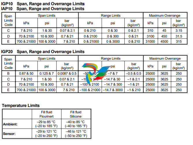
Span Limits - Absolute or Gauge Pressure Units, as Applicable
MPa psi bar or kg/cm²
0.007 and 0.21 1 and 30 0.07 and 2.1..............................C
0.07 and 2.1 10 and 300 0.7 and 21 ..............................D
0.7 and 21 100 and 3000 7 and 210 .............................E
Conduit Connection
1/2 NPT Conduit Connection, Both Sides ...................................1
PG 13.5 Conduit Connection, Both Sides (available only with Electrical Safety CodesE&N .........2
Electrical Safety (See Electrical Safety Specifications Section)
CENELEC Certified Intrinsically Safe, ia ......................................E
CSA Certified ....................................................N
EUROPEAN Ex, N, IIC. Nonsparking ........................................C
FM Approved ....................................................F
SAA Certified, EEx, d, IIC ..............................................A
Options
Mounting Bracket Set
Painted Steel Bracket with Plated Steel Bolts . . . . . . . . . . . . . . . . . . . . . . . . . . . . . . . . . . . . . . . M1
Stainless Steel Bracket with Stainless Steel Bolts . . . . . . . . . . . . . . . . . . . . . . . . . . . . . . . . . . . . . M2
Digital Indicator with Pushbuttons (standard equipment on IGP10-I)
Digital Indicator, Pushbuttons, and Window Cover (for Electr VersionD&T only) . . . . . . . . . . . . . . . . . . . . . -L1
Vent Screw and Block & Bleed Valve
Vent Screw in Process Connection for IGP10/IAP10; or in High Side Process Cover for IGP20. . . . . . . . . . . . . . . V1
Block and Bleed Valve, Carbon Steel . . . . . . . . . . . . . . . . . . . . . . . . . . . . . . . . . . . . . . . . . . . V2
Block and Bleed Valve, 316 ss. . . . . . . . . . . . . . . . . . . . . . . . . . . . . . . . . . . . . . . . . . . . . . . V3
Block and Bleed Valve, 316 ss Body w/Monel Trim (NACE Approved) . . . . . . . . . . . . . . . . . . . . . . . . . . . V4
Conduit Thread Adapters
Hawke-Type 1/2 NPT Cable Gland for use with Conduit Connection Code “1” . . . . . . . . . . . . . . . . . . . . . . . A1
Plastic PG 13.5 Connector for use with Conduit Connection Code “2” (available only with Electrical Safety Codes E & N) . A2
M20 Connector for use with Conduit Connection Code “1” . . . . . . . . . . . . . . . . . . . . . . . . . . . . . . . . . A3
Electronics Housing Features
External Zero Adjustment . . . . . . . . . . . . . . . . . . . . . . . . . . . . . . . . . . . . . . . . . . . . . . . . . Z1
Custody Transfer Lock and Seal . . . . . . . . . . . . . . . . . . . . . . . . . . . . . . . . . . . . . . . . . . . . . . Z2
External Zero Adjustment and Custody Transfer Lock and Seal . . . . . . . . . . . . . . . . . . . . . . . . . . . . . . Z3
Factory Configuration
Digital Output (4 to 20 mA Default if not selected) . . . . . . . . . . . . . . . . . . . . . . . . . . . . . . . . . . . . . C1
Full Factory Configuration (Requires Configuration Form to be filled out) . . . . . . . . . . . . . . . . . . . . . . . . . . C2
Miscellaneous Optional Selections
G 1/2 B Manometer Process Connection (Not Available with Option “-V1”) .........................G
-
 Hirschmann RS20-1600M2T1SDAEHH03.1.02 Rail Switch
 -
 Hirschmann BRS30-24TX Industrial Rail Switch
 -
 Hirschmann RSPM20-4T14T1EV9HHS999.9.99 Managed Ethernet Switch
 -
 Hirschmann BELDEN RS40-0009CCCCSDAPHH09.0.14 / RS400009CCCCSDAPHH09014
 -
Hirschmann RS40 Rail Switch RS40-0009CCCCSDAE
-
 Hirschmann BELDEN RS30-0802T1T1SDAP / RS300802T1T1SDAP Fully Managed Layer 2 Compact Rail Switch
 -
 Hirschmann BELDEN RS20-0800M2M2SDAUHH / RS200800M2M2SDAUHH
 -
 Hirschmann EAGLE30-04022O6TT999SCCY9HSE3F Industrial Firewall Router Switch
 -
 Hirschmann RS20-1600T1T1SDAEHH09.0.14 RS20 Rail Mount Ethernet Switch
 -
 Hirschmann EAGLE0200T1T1TDDY90000HHE05.3.03 Industrial Security Router
 -
Hirschmann - BELDEN MIPP-AD-1L9P
-
 HIRSCHMANN RSPM20-4Z64Z6TV9HHS9 942 106-999 RAIL SAFETY SWITCH
 -
 HIRSCHMANN FIBEROPTIC MODULE FIP P/N: OZDFIPG3T
 -
 HIRSCHMANN RS20-1600M2M2SDAUHH Ethernet rack-mounted switch
 -
 HIRSCHMANN BELDEN RS20-0400T1T1SDAEHH04.0.01 / RS200400T1T1SDAEHH04001
 -
HIRSCHMANN MM2-4FXM3 MICE Media Module
-
HIRSCHMANN RS20-0800M2M2SDAE Industrial Ethernet Rail Switch
-
 Hirschmann RS20-2400T1T1SDAP / RS20-2400T1T1SDAPHH05.0.02
 -
 GE MLJ1005B010H00C MLJ Digital Synchromism Check
 -
 ALSTOM MICROTECH DX21-M2 Digital Excitation Controller
 -
HIRSCHMANN BRS20-1200ZZZZ-STCY99HHSES
-
 HIRSCHMANN MM3-4FXM2 MICE Media Module
 -
Hirschmann RSB20-0800T1T1SAABHH 8Port ENet Rail Switch RSB20
-
 Hirschmann MACH102-8TP Ethernet Switch
 -
 SAACKE DDZ-M marine steam pressure atomizer
 -
 SAACKE SKV-A marine rotary cup atomizer
 -
 SAACKE Seavis HMI05e
 -
 Kollmorgen MMC-SD-2.0-230 Servo Drive 100-240VAC 2KW 10A Output 3PH 100-240VAC
 -
 Kollmorgen Servo drive CR10550
 -
 Kollmorgen AKD-P01207-NACN-0054 Servo Driver
 -
 Kollmorgen S406M-CA-036 Servostar
 -
.png) Kollmorgen AKD-B02407-NAAN-0000 Digital Servo Drive
Kollmorgen AKD-B02407-NAAN-0000 Digital Servo Drive -
 Kollmorgen SERVOSTAR S406AM-CA Digital Servo Drive
 -
 KOLLMORGEN SERVOSTAR 603-AS SERVO AMPLIFIER_SERVOSTAR603AS_S60301
 -
Kollmorgen S700 Servo Controller (S70602-NANANA-NA)
-
 Kollmorgen MPK411 controller
 -
 KOLLMORGEN MMC-SD-1.3-460-D Smart Drive
 -
 KOLLMORGEN AKM21C-CKB2AA-00 / AKM21CCKB2AA00 Servomotor
 -
 BECKHOFF AX5106-0000-0200 | Digital Compact Servo Drives 1-channel
 -
 BECKHOFF C3620-0000 INDUSTRIAL COMPUTER (MOTORSHELVES)
 -
 Beckhoff EK1960-0000 TwinSAFE Compact Controller
 -
 Beckhoff C6930-0050 Control Cabinet Industrial PC
 -
 Beckhoff CP7711-0001-0030 Industrial Computer Detection
 -
 Beckhoff CX1001-0111 Embedded PC CPU Module
 -
 Beckhoff C6017-0020 | Ultra-compact Industrial PC
 -
 Beckhoff EK1322 | 2-port EtherCAT P junction with feed-in
 -
 Beckhoff CP2219-0010 Panel
 -
 BECKHOFF C6015-0020 ULTRA COMPACT INDUSTRIAL PC
 -
 BECKHOFF CX2030-0120/Standard CPU Module Embedded PC Windows PLC controller
 -
 Beckhoff CP7721-1090-0020 Panel PC
 -
 Beckhoff PC CPU Module CX5130-0175
 -
 Beckhoff C6920-0050 Control Cabinet
 -
 Beckhoff EL6631 EtherCAT 2-Port Communication Interface, Profinet RT Controller
 -
 Beckhoff CP6202-0001-0060 touch screen panel PC
 -
 Beckhoff CP3916-1002-0000 Multi-Touch Control Panel
 -
 Beckhoff EP1809-0021 | EtherCAT Box, 16-channel digital input, 24 V DC, 3 ms, M8Preferred type
 -
 Beckhoff CX8190 PLC Embedded Industrial PC Ethernet Controller
 -
 Beckhoff CX2100-0914 Power Supply for External
 -
 Beckhoff Automation CP6906-0001-0000 HMI
 -
 Beckhoff EP7342-0002 Module
 -
 Beckhoff CX1020-0112 / CX1100-0910 / CX1020-N010 / CX1100-0003 Windows CPU
 -
 Beckhoff EP7211-0034 EtherCAT Box 1 Channel Motion Interface
 -
 Beckhoff C6240-0030 Control cabinet Industrial PC
 -
 beckhoff motherboard CB1052-0004 CB1052-0004
 -
 Beckhoff AX2006-AS Servo Drive / Variable Frequency Drive
 -
BECKHOFF CP6207-0001-0020 NSMP
-
 Beckhoff C6930-1142-0060 Industrial Computer
 -
 Beckhoff FC7501-0000 interface card
 -
 Beckhoff CX5140-0175 Embedded PC PLC CPU CX5140 Industrial Controller
 -
 Beckhoff CP7802-1100-0010: High-End IP65 Control Panel with DVI/USB Extended Interface
 -
BECKHOFF CP3716-1058-0010 CONTROL PANEL
-
 Beckhoff AX8108-0000 Single-Axis Module
 -
 Beckhoff CU8851-0000 | USB extension, USB Extended 2.0 receiver box
 -
Beckhoff C6017-0030 | Ultra-compact Industrial PC
-
 Beckhoff CX1001-0120/CX10010120.cx1000-n001.cx1000-n000 System Overview
 -
 Beckhoff CPU Module CX5140-0155/4GB CPU Module
 -
 Beckhoff CP6533-0001-005: Built-in Panel PC with High-Definition Multi-Touch Control
 -
 Beckhoff EL5042 | EtherCAT Terminal, 2-channel encoder interface, BiSS® C
 -
 Beckhoff C6920-1080-0040: Premium Control Cabinet Industrial PC
 -
 Beckhoff C6920-0060 | Control cabinet Industrial PC
 -
 Beckhoff Embedded-PC CX5010-1121
 -
 Beckhoff CB3050-0010 Mainboard Motherboard
 -
 Beckhoff PLC module CX1020-0000 Basic CPU module (service phase)
 -
 Beckhoff CP7812-1056-0010 15" Multitouch Display Control Panel
 -
 Beckhoff CX5120-0115 /2GB Controller Module
 -
 Beckhoff CP7201-1000-0000 Industrial Panel PC
 -
 Beckhoff Servo Motor AM8061-0JH1-0000
 -
 BECKHOFF CP6503-0001-0050 Built-in Panel PC
 -
Beckhoff CP3919-0010 Display G190ETN01.2 19" PCT V04. Multi-touch Control Panel
-
 Beckhoff CX5110-0112-9020/000368201 Embedded PC Intel Atom Processor
 -
 Beckhoff AX8206-0000 Dual-Axis Module
 -
Beckhoff Nail Operating Terminal CP7032-1031-0010
-
Beckhoff AM8042-0EH1-0000 Servomotor 4.10 Nm (M0), F4 (87 mm)
-
 Beckhoff EK9300 Beckhoff CPU Module
 -
Beckhoff CP3224-0020 Multitouch-Panel-PC
-
 Beckhoff CP2712-0000 12.1" 24VDC Touch Screen WMD0
 -
 BECKHOFF CX5240-0195 / 0000289234 Embedded PC 40 GB CFast Card
 -
 Beckhoff CP6932-1000-0000 Control Panel
 -
 BECKHOFF CX5120-0121 PLC Module
 -
 Beckhoff EL3218 | EtherCAT Terminal, 8-channel analog input
 -
Beckhoff C6640-0050 | Control cabinet Industrial PC
-
 Beckhoff Cx5130-0120/4GB Embedded-PC
 -
 BECKHOFF CX2030-0122 PLC PROCESSOR
 -
 BECKHOFF CX5020-0122 Controller Module
 -
 Beckhoff CP3915-0000 Multitouch Panel
 -
 BECKHOFF EL3014 | EtherCAT Terminal
 -
 BECKHOFF Industrial Computer c6920-1057-0030
 -
 Beckhoff CX5130-0141/4GB CX5130-0141 Embedded PC
 -
 Beckhoff C6240-1052-0040 4-086-06-3073 Industrial Computer
 -
 Beckhoff CX5140-0135 /4GB High-Performance Embedded Industrial PC
 -
 Beckhoff C6515-1001-0000 Industrial PC
 -
 Beckhoff AX5103-0000-0200 - Digital Compact Servo Drives
 -
 Beckhoff CX2030-0130-1003/4GB Basic CPU module
 -
 Beckhoff AX8620-0000 Power Supply Module
 -
 Beckhoff CX9020-0111 module with
 -
 Beckhoff EL7332 PLC Module
 -
 BECKHOFF CP7709-0001-0020 HMI
 -
 Beckhoff CX5120-0155/2GB Embedded PC
 -
 BECKHOFF CP7037-1037-0010 OPERATOR INTERFACE TOUCHSCREEN
 -
 Beckhoff EK9000 | ModbusTCP/UDP Bus Coupler
 -
 Beckhoff Touch Panel Screen CP6020 -0000-0000
 -
 Beckhoff CX2020-0121 Module FAST Shipping
 -
 Beckhoff CX2030-0125 Basic CPU Module
 -
 Beckhoff CP3918-0000 Multi-Touch 18.5" Control Panel
 -
 Automotion LC4A00010 DC BL Motor Control, ATS, Sub Assy, SCP, 115VAC,
 -
 500T-115VAC - VAS ENGINEERING - DORIC 500 SERIES DIGITAL TEMP INDICATOR
 -
 Honeywell X-DCS2000/EN Digital Integrated System Manager 50/60Hz 100-240V #4
 -
 Kollmorgen S60600 Servostar600 606-Fan 4 kVA, 6 A, 3 X 230 - 480 V


