
REXRTOHECODRIVE03 Drive ControllersProject Planning Manual
"ECODRIVE03 Drive for General Automation With Fieldbus-Interfaces"
- Functional Description -
DOK-ECODR3-FGP-03VRS**-FKxx-EN-P
"LWL - Handling"
- Application Manual -
DOK-CONNEC-CABLE*LWL-AWxx-EN-P
"Electromagnetic Compatibility (EMC) in Drive and Control Systems"
- Project Planning Manual -
DOK-GENERL-EMV********-PRxx-EN-P
"Digital AC Motors MKD"
- Project Planning Manual -
DOK-MOTOR*-MKD********-PRxx-EN-P
"Digital AC Motors MHD"
- Project Planning Manual -
DOK-MOTOR*-MHD********-PRxx-EN-P
"MKE Digital AC Motors for potentially explosive areas"
- Project Planning Manual -
DOK-MOTOR*-MKE********-PRxx-EN-P
"2AD AC Motor"
- Project Planning Manual -
DOK-MOTOR*-2AD********-PRxx-EN-P
"ADF Main Spindle Motors"
- Project Planning Manual -
DOK-MOTOR*-ADF********-PRxx-EN-P
"1MB Frameless Spindle Motor"
- Project Planning Manual -
DOK-MOTOR*-1MB********-PRxx-EN-P
"Synchronous MBS Kit Spindle Motors"
- Project Planning Manual -
DOK-MOTOR*-MBS********-PRxx-EN-P
LAR 070-132 Gehäuse-Linearmotoren
- Selection and Project Planning -
DOK-MOTOR*-LAR********-AWxx-DE-P
"LAF050 – 121 Linear Motors"
- Selection and Project Planning -
DOK-MOTOR*-LAF********-AWxx-EN-P
"Linear Synchronous Direct Drives LSF"
- Project Planning Manual -
DOK-MOTOR*-LSF********-PRxx-EN-P
"AC Drive Units in Personnel Conveyor Systems"
- Application Manual -
DOK-GENERL-ANTR*PERSON-ANxx-EN-P
"AC Drive Units in Hazardous Areas (Expl. Protection)"
- Application Manual -
DOK-GENERL-ANTR*EXPLOS-ANxx-EN-P
"ECODRIVE03 Drive for Machine Tool Applications With SERCOS-,
Analog- and Parallelinterface"
- Troubleshooting Guide -
DOK-ECODR3-SMT-01VRS**-WAR*-EN-P
"ECODRIVE03 Drive for Machine Tool Applications With SERCOS-,
Analog- and Parallelinterface"
- Troubleshooting Guide -
DOK-ECODR3-SMT-02VRS**-WAR*-EN-P
"ECODRIVE03 Drive for General Automation With SERCOS-, Analogand Parallelinterface"
- Troubleshooting Guide -
DOK-ECODR3-SGP-01VRS**-WAxx-EN-P
"ECODRIVE03 Drive for General Automation With Fieldbus-Interfaces"
- Troubleshooting Guide -
DOK-ECODR3-FGP-01VRS**-WAxx-EN-P
"ECODRIVE03 Drive for General Automation With Fieldbus-Interfaces"
- Troubleshooting Guide -
DOK-ECODR3-FGP-02VRS**-WAxx-EN-P
"ECODRIVE03 Drive for General Automation With Fieldbus-Interfaces"
- Troubleshooting Guide -
DOK-ECODR3-FGP-03VRS**-WAxx-EN-P
"DOLFI, Auxiliary for Download Firmware"
- Application Manual -
DOK-DOLFI DO01D**W
ntroduction to the System
1.1 Drive package ECODRIVE03
The digital intelligent automation system ECODRIVE03 is the costeffective solution with a high level of functionality for single and multiple
axis drive and control tasks.
ECODRIVE03 can be used to implement a variety of drive tasks in the
most varied applications. Different device types are available with
graduated drive power.
Typical application areas are:
• handling systems
• packaging machines
• assembly systems
• printing machines
• machine tools
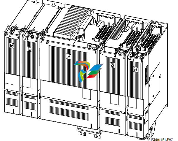
An Overview of Individual Components of the
ECODRIVE03 Family
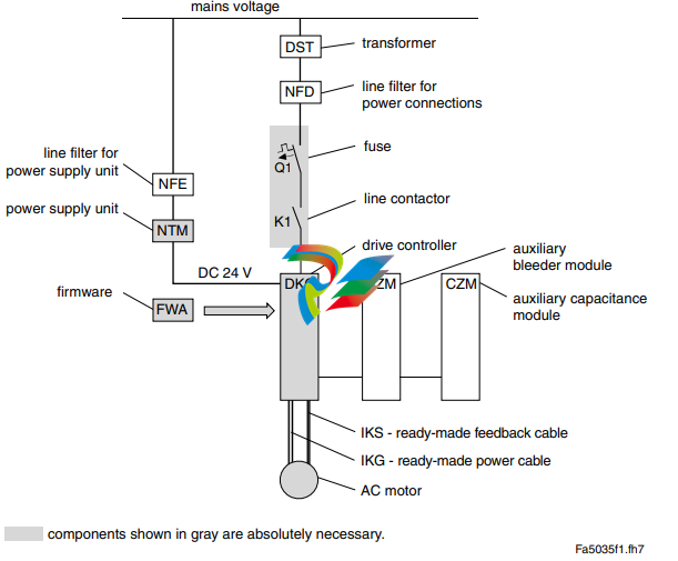
An Overview of Drive Controllers and Auxiliary
Components
An Overview of Communications Interfaces
mportant directions for use 2.1 Appropriate use Introduction Rexroth Indramat products represent state-of-the-art developments and manufacturing. They are tested prior to delivery to ensure operating safety and reliability. The products may only be used in the manner that is defined as appropriate. If they are used in an inappropriate manner, then situations can develop that may lead to property damage or injury to personnel. Note: Rexroth Indramat, as manufacturer, is not liable for any damages resulting from inappropriate use. In such cases, the guarantee and the right to payment of damages resulting from inappropriate use are forfeited. The user alone carries all responsibility of the risks. Before using Rexroth Indramat products, make sure that all the prerequisites for an appropriate use of the products are satisfied: • Personnel that in any way, shape or form uses our products must first read and understand the relevant safety instructions and be familiar with appropriate use. • If the product takes the form of hardware, then they must remain in their original state, in other words, no structural changes are permitted. It is not permitted to decompile software products or alter source codes. • Do not mount damaged or faulty products or use them in operation. • Make sure that the products have been installed in the manner described in the relevant documentation.
Areas of use and application
Drive controllers made by Rexroth Indramat are designed to control
electrical motors and monitor their operation.
Control and monitoring of the motors may require additional sensors and
actors.
Note: The drive controllers may only be used with the accessories
and parts specified in this document. If a component has not
been specifically named, then it may not be either mounted or
connected. The same applies to cables and lines.
Operation is only permitted in the specified configurations and
combinations of components using the software and firmware
as specified in the relevant function descriptions.
Every drive controller has to be programmed before starting it up, making
it possible for the motor to execute the specific functions of an application.
The drive controllers of the ECODRIVE03 family are designed for use in
single or multiple-axis drive and control applications.
To ensure an application-specific use, the drive controllers are available
with differing drive power and different interfaces.
Typical applications of drive controllers belonging to the ECODRIVE03
family are:
• handling and mounting systems,
• packaging and foodstuff machines,
• printing and paper processing machines and
• machine tools.
The drive controllers may only be operated under the assembly,
installation and ambient conditions as described here (temperature,
system of protection, humidity, EMC requirements, etc.) and in the
position specified.
2.2 Inappropriate use
Using the drive controllers outside of the above-referenced areas of
application or under operating conditions other than described in the
document and the technical data specified is defined as “inappropriate
use".
Drive controllers may not be used if
• they are subject to operating conditions that do not meet the above
specified ambient conditions. This includes, for example, operation
under water, in the case of extreme temperature fluctuations or
extremely high maximum temperatures or if
• Rexroth Indramat has not specifically released them for that intended
purpose. Please note the specifications outlined in the general safety
instructions!
Safety Instructions for Electric Drives and Controls
3.1 Introduction
Read these instructions before the initial startup of the equipment in order
to eliminate the risk of bodily harm or material damage. Follow these
safety instructions at all times.
Do not attempt to install or start up this equipment without first reading all
documentation provided with the product. Read and understand these
safety instructions and all user documentation of the equipment prior to
working with the equipment at any time. If you do not have the user
documentation for your equipment, contact your local Rexroth Indramat
representative to send this documentation immediately to the person or
persons responsible for the safe operation of this equipment.
If the equipment is resold, rented or transferred or passed on to others,
then these safety instructions must be delivered with the equipment.
WARNING
Improper use of this equipment, failure to follow
the safety instructions in this document or
tampering with the product, including disabling
of safety devices, may result in material
damage, bodily harm, electric shock or even
death!
3.2 Explanations
The safety instructions describe the following degrees of hazard
seriousness in compliance with ANSI Z535. The degree of hazard
seriousness informs about the consequences resulting from noncompliance with the safety instructions.
Warning symbol with signal
word
Degree of hazard seriousness according
to ANSI
DANGER
Death or severe bodily harm will occur.
WARNING
Death or severe bodily harm may occur.
CAUTION
Bodily harm or material damage may occur
Hazards by Improper Use
DANGER
High voltage and high discharge current!
Danger to life or severe bodily harm by electric
shock!
DANGER
Dangerous movements! Danger to life, severe
bodily harm or material damage by
unintentional motor movements!
WARNING
High electrical voltage due to wrong
connections! Danger to life or bodily harm by
electric shock!
WARNING
Health hazard for persons with heart
pacemakers, metal implants and hearing aids in
proximity to electrical equipment!
CAUTION
Surface of machine housing could be extremely
hot! Danger of injury! Danger of burns!
CAUTION
Risk of injury due to improper handling! Bodily
harm caused by crushing, shearing, cutting and
mechanical shock or incorrect handling of
pressurized systems!
CAUTION
Risk of injury due to incorrect handling of
batteries!
General Information
• Rexroth Indramat GmbH is not liable for damages resulting from
failure to observe the warnings provided in this documentation.
• Read the operating, maintenance and safety instructions in your
language before starting up the machine. If you find that you cannot
completely understand the documentation for your product, please ask
your supplier to clarify.
• Proper and correct transport, storage, assembly and installation as
well as care in operation and maintenance are prerequisites for
optimal and safe operation of this equipment.
• Only persons who are trained and qualified for the use and operation
of the equipment may work on this equipment or within its proximity.
The persons are qualified if they have sufficient knowledge of the
assembly, installation and operation of the equipment as well as an
understanding of all warnings and precautionary measures noted in
these instructions.
Furthermore, they must be trained, instructed and qualified to switch
electrical circuits and equipment on and off in accordance with
technical safety regulations, to ground them and to mark them
according to the requirements of safe work practices. They must
have adequate safety equipment and be trained in first aid.
• Only use spare parts and accessories approved by the manufacturer.
• Follow all safety regulations and requirements for the specific
application as practiced in the country of use.
• The equipment is designed for installation in industrial machinery.
• The ambient conditions given in the product documentation must be
observed.
• Use only safety features and applications that are clearly and explicitly
approved in the Project Planning Manual.
For example, the following areas of use are not permitted: construction
cranes, elevators used for people or freight, devices and vehicles to
transport people, medical applications, refinery plants, transport of
hazardous goods, nuclear applications, applications sensitive to high
frequency, mining, food processing, control of protection equipment
(also in a machine).
• The information given in this documentation with regard to the use of
the delivered components contains only examples of applications and
suggestions.
The machine and installation manufacturer must
make sure that the delivered components are suited for his individual
application and check the information given in this documentation
with regard to the use of the components,
make sure that his application complies with the applicable safety
regulations and standards and carry out the required measures,
modifications and complements.
• Startup of the delivered components is only permitted once it is sure
that the machine or installation in which they are installed complies
with the national regulations, safety specifications and standards of the
application.
• Operation is only permitted if the national EMC regulations for the
application are met.
The instructions for installation in accordance with EMC requirements
can be found in the documentation "EMC in Drive and Control
Systems".
The machine or installation manufacturer is responsible for
compliance with the limiting values as prescribed in the national
regulations.
• Technical data, connections and operational conditions are specified in
the product documentation and must be followed at all times.
Protection Against Contact with Electrical Parts
Note: This section refers to equipment and drive components with
voltages above 50 Volts.
Touching live parts with voltages of 50 Volts and more with bare hands or
conductive tools or touching ungrounded housings can be dangerous and
cause electric shock. In order to operate electrical equipment, certain
parts must unavoidably have dangerous voltages applied to them.
DANGER
High electrical voltage! Danger to life, severe
bodily harm by electric shock!
⇒ Only those trained and qualified to work with or on
electrical equipment are permitted to operate, maintain
or repair this equipment.
⇒ Follow general construction and safety regulations when
working on high voltage installations.
⇒ Before switching on power the ground wire must be
permanently connected to all electrical units according
to the connection diagram.
⇒ Do not operate electrical equipment at any time, even
for brief measurements or tests, if the ground wire is not
permanently connected to the points of the components
provided for this purpose.
⇒ Before working with electrical parts with voltage higher
than 50 V, the equipment must be disconnected from
the mains voltage or power supply. Make sure the
equipment cannot be switched on again unintended.
⇒ The following should be observed with electrical drive
and filter components:
⇒ Wait five (5) minutes after switching off power to allow
capacitors to discharge before beginning to work.
Measure the voltage on the capacitors before beginning
to work to make sure that the equipment is safe to
touch.
⇒ Never touch the electrical connection points of a
component while power is turned on.
⇒ Install the covers and guards provided with the
equipment properly before switching the equipment on.
Prevent contact with live parts at any time.
⇒ A residual-current-operated protective device (RCD)
must not be used on electric drives! Indirect contact
must be prevented by other means, for example, by an
overcurrent protective device.
⇒ Electrical components with exposed live parts and
uncovered high voltage terminals must be installed in a
protective housing, for example, in a control cabinet.
-
 HIRSCHMANN MSM20-M2M2M2M2SY9HH9E Ethernet media modul
 -
 HIRSCHMANN SPIDER-PL-20-05T1999999TWVHHHH Industrial Ethernet Rail Switch
 -
 Hirschmann SPIDER-PL-20-07T1M2M299TWVHHHH Industrial ETHERNET Rail Switch
 -
.png) Hirschmann (Belden) RS20-1600M2M2SDAEHC09.1.00 DIN-rail managed industrial Fast Ethernet switch
Hirschmann (Belden) RS20-1600M2M2SDAEHC09.1.00 DIN-rail managed industrial Fast Ethernet switch -
 Hirschmann (Belden) RS30-1602O6O6TDAPHC09.1.00 DIN-rail managed industrial Ethernet switch
 -
 Hirschmann (Belden) RS30-2402O6T1SDAPHH09.0.13 DIN-rail industrial Ethernet switch
 -
Hirschmann (Belden) SPIDER-PL-20-04T1S29999TY9HHHH Ethernet DIN-rail switch
-
 HIRSCHMANN RS20-1600T1T1SDAUHX Switch
 -
 HIRSCHMANN BRS42-0012OOOO-SPCZ99HHSES industrial switch
 -
 Hirschmann RS20-0800S2S2TDHPHH09.0.14 Fast Ethernet DIN rail switch.
 -
 HIRSCHMANN MM20-Z6Z6M2M2SAHH Hybrid Fast Ethernet Media Module
 -
 HIRSCHMANN MM20-Z6Z6T1T1SAHH hot-swappable hybrid Fast Ethernet Media Module
 -
 HIRSCHMANN MM20-P9P9T1T1SAHH Hybrid Fast Ethernet Media Module
 -
 HIRSCHMANN MM20-M4T1T1T1SAHH Hybrid Fast Ethernet Media Module
 -
 HIRSCHMANN MM20-M4M4T1T1SAHH Hybrid Fast Ethernet Media Module
 -
 HIRSCHMANN MM20-M2M2M2M2SZHH Ethernet media module
 -
HIRSCHMANN MM20-M2M2M2M2SAHH Ethernet media module
-
 HIRSCHMANN MM20-T1T1T1T1EBH 4-port Fast Ethernet Copper Cable Media Module
 -
HIRSCHMANN MM20-T1T1T1T1SAHH 4-port Fast Ethernet Copper Cable Media Module
-
HIRSCHMANN MM20-T1T1T1T1SAHH 4-port Fast Ethernet Copper Cable Media Module
-
 HIRSCHMANN MM20-Z6Z6EBH Hot-swappable fast Ethernet media module
 -
 HIRSCHMANN MM20-Z6Z6SAHH Ethernet media module
 -
HIRSCHMANN MM20-Z6Z6Z6Z6EBH Industrial Media Module
-
 MSM40-T1T1T1TZ9HH9E99.9.99 HIRSCHMANN Switch
 -
 HIRSCHMANN MS20-0800SAAEHC / MS20-0800SAAEHC0 8-port modular Layer 2 management Ethernet switch
 -
 Hirschmann RSPM20-4T14T1SZ9HHS9 Switch RSPM20-4T14T1SZ9HHS9
 -
 HIRSCHMANN RS20-1600M2M2SDAEHH09.1. RS20/30/40 Managed Switch configurator
 -
HIRSCHMANN RS20-1600M2M2SDAEHX09.0.00 Ethernet switch
-
 HIRSCHMANN BELDEN SPIDER-PL-20-07T1M2M299TY9HHHH / SPIDERPL2007T1M2M299TY9HHHH
 -
HIRSCHMANN MM3-1FXS2/3TX1 Switching Board Module
-
 HIRSCHMANN RSPE30-24044O7T99-ECCP999HHSE2A08.1.00 Industrial-grade fanless management-type Ethernet switch
 -
 HIRSCHMANN RS30-1602OOZZSDAEHC09.1.00 DIN-rail-mounted managed Layer 2 Ethernet switch
 -
 HIRSCHMANN MACH104-20TX-F Managed 24-port Full Gigabit 19" Switch
 -
 HIRSCHMANN Switch RS20-0800M4M4SDAE
 -
Hirschmann RS30-1602O6O6SDAEHH09.1. Management-type Ethernet switch
-
 Hirschmann RS30-1602OOZZSDAEHC09.0.10 Open rack-style Ethernet switch
 -
 HIRSCHMANN RSPE30-24044O7T99-SCCV999HHSI2SXX.X.XX High-Availability Seamless Redundancy
 -
HIRSCHMANN RSPE30-24044O7T99-SCCZ999HHSE2A DIN-rail Ethernet switch
-
HIRSCHMANN MM2-4TX1-EEC switch
-
HIRSCHMANN MSM40-T1T1T1T1TZ9HH9E99.9.99 Module
-
 HIRSCHMANN RS20 Rail Switch RS20-0400S4T1SDAEHC07.1.01
 -
 HIRSCHMANN M4-FAST8-SFP Fast Ethernet media module
 -
 HIRSCHMANN RS20-0400M2T1SDAP Managed Fast-Ethernet-Switch
 -
 HIRSCHMANN BELDEN SPIDER II 8TX/1FX EEC Industrial Ethernet Rail Switch
 -
HIRSCHMANN MM3-2FXS2/2TX1
-
 HIRSCHMANN RS2-4TX/1FX EEC Industrial Ethernet Rail Switch
 -
 RS30-0802O6O6SDAEHC09.0.10 HIRSCHMANN Switch
 -
 HIRSCHMANN m4-8TP-RJ45 Ethernet Media Module
 -
 HIRSCHMANN MSP30-24040SCZ9URHHE3A switch
 -
 Hirschmann rack MS30-1602SAAPHC
 -
 HIRSCHMANN RS2-FX/FX Industrial Switch Module
 -
Rs1txfx - Hirschmann - Rs1-Tx/Fx Rail Switch
-
RS20-0800S2S2SDAEHC09.1.00 HIRSCHMANN Commutator
-
 Hirschmann EAGLE20 TX/TX Industrial Security Router
 -
 Hirschmann SPIDER-SL-20-04T1S29999SY9HHHH Industrial Switch
 -
 HIRSCHMANN MAR1040-4C4C4C4C9999SMMHRHHXX.X. Gigabit Ethernet Switch configurator
 -
 Hirschmann MAR1040 Industrial Switch
 -
 HIRSCHMANN BELDEN RS30-1602O6O6SDAE
 -
Hirschmann RS20-1600M2M2SDAUHC Ethernet DIN rail switch
-
 HIRSCHMANN OCTOPUS 24M industrial switch
 -
 HIRSCHMANN RS20-1600T1T1SDAE Management-type Ethernet switch
 -
 HIRSCHMANN RS20-1600T1T1SDAUHH industrial switch
 -
HIRSCHMANN RS20-0800M2M2SDAPHC09.0.04 switch
-
 Hirschmann MR 8-03 24V DC Industrial Modular Bridge/Router
 -
 HIRSCHMANN RS20-0400M2T1SDAPHC08.0.01 Managed Switch
 -
 MACH1130 Hirschmann Industrial Switch
 -
 HIRSCHMANN 943824-002 SPIDER 5TX Industrial Ethernet Switch
 -
 HIRSCHMANN RS30-0802O6O6SDAEHC09.1.00 Managed Industrial Switch
 -
 HIRSCHMANN RS20-0400M2M2TDAEHC04.0.01 Industrial Switch
 -
 HIRSCHMANN BRS20-0600Z6Z6-STCZ99HHSES Industrial Switch
 -
 HIRSCHMANN MACH104-20TX-FR-L3P Industrial Ethernet Switch
 -
 HIRSCHMANN RS40-0009CCCCEDBPHH06.0.01 Industrial Switch
 -
 HIRSCHMANN RS2-3TX/2FX EEC Industrial Ethernet Switch
 -
 Hirschmann MACH 1020/1030 Fast/Gigabit Rack Mount Switches
 -
HIRSCHMANN RS20-0800M2M2SDAPHC09.0.14 Industrial Switch
-
 HIRSCHMANN RS20-1600T1T1SDAEHC09.0.04 Industrial Switch
 -
 HIRSCHMANN RSB20-0800T1T1EAABHH Industrial Switch
 -
 HIRSCHMANN MACH4002-48+4G-L3E Industrial Backbone Switch
 -
 HIRSCHMANN RS20-0400S2T1SDAE Industrial Managed Switch
 -
HIRSCHMANN RS20-0800S2T1SDAUHC Industrial Switch
-
 HIRSCHMANN RS20-2400S4S4SDAEHC09.0.14 industrial switch
 -
 HIRSCHMANN OS20-001200T5T5T5- TBBZ999HHNE3S 08.1.00 industrial switch
 -
HIRSCHMANN OS20-001200T5T5T5- TBBZ999HHNE3S 08.1.00 industrial switch
-
 HIRSCHMANN RS40-0009CCCCSDAEHH09.0.14 switch
 -
 Hirschmann RS20-1600T1T1SDAUHC Management-type Ethernet Switch
 -
 Hirschmann M1-8SFP Switche
 -
Hirschmann Industrial Ethernet Ruggedized Switch MACH1000 Family
-
 Basler Electric, Solid State Protective Relay, BE1-60
 -
BASLER ELECTRIC SR4A-2B15B3A Static Voltage Regulator
-
.png) BASLER ELECTRIC EXCITER DIODE MONITOR EDM-200
BASLER ELECTRIC EXCITER DIODE MONITOR EDM-200 -
.png) BASLER ELECTRIC DECS125-15-B2C5 DIGITAL EXCITATION CONTROL SYSTEM V 2.0.9
BASLER ELECTRIC DECS125-15-B2C5 DIGITAL EXCITATION CONTROL SYSTEM V 2.0.9 -
 BASLER ELECTRIC BE1-851 OVERCURRENT PROTECTION RELAY MECHANISM
 -
 Basler Electric BE1-51A / BE151A
 -
 Basler Electric BE1-40Q Loss of Excitation Relay
 -
 Basler Electric BE1-87G Variable Percentage Differential Relay
 -
 Basler Electric BE1-11 Protection System I5A3M2P2N0EA00
 -
 BASLER ELECTRIC DECS-200-1C Digital Excitation Control System
 -
 Basler Electric / Kohler BE1-11g Generator Protection Relay G5A3M2J2N0E000
 -
BASLER ELECTRIC DECS125-15 DIGITAL EXCITATION CONTROL SYSTEM
-
 BASLER ELECTRIC BE1-951 OverCurrent Protecton System
 -
Basler Electric DECS-200-1L Digital Excitation Control System
-
 Basler Electric DGC-2020HD-5NS1DNSBA Digital Genset Controller -
 -
 BASLER ELECTRIC BE1-81T1EE1WA0N1F / BE181T1EE1WA0N1F
 -
 BASLER ELECTRIC BE1-25M1EA6PN5R1F / BE125M1EA6PN5R1F
 -
 BASLER ELECTRIC DECS-250-LN1SN1N DIGITAL EXCITATION CONTROL SYSTEM
 -
Basler Electric DECS-250-CN2CN 1N Digital Excitation Control System Unit
-
 BASLER ELECTRIC DECS-300-C0N0 DIGITAL EXCITATION CONTROL SYSTEM
 -
 BASLER ELECTRIC BE1-87T-A1E-A1J-D0S1F / BE187TA1EA1JD0S1F
 -
BASLER ELECTRIC BE1-11-G6D1M0J2P0E000 Protection System
-
 BASLER ELECTRIC BE1-GPS100-E4N1H1N GENERATOR PROTECTION SYSTEM
 -
 Jaquet Relay card (Auxiliary module) FTV 3090 377Z-03985
 -
 Jaquet Trip Chain Control card FTBU 3034 377Z-05030
 -
 Jaquet with input card -E04 FTFU 3024 -E04 377Z-05855
 -
 Jaquet with input card -E03 FTFU 3024- E03 377Z-03983
 -
 Jaquet FTFU 3024- E02 377Z-03982 with input card -E02
 -
 Jaquet FTFU 3024-E01 377Z-03981 with input card -E01
 -
 Hirschmann RS20-2400T1T1SDAE Industrial Managed Ethernet Switch
 -
 Hirschmann BELDEN EAGLE30-04022O6TT999SCCV9HSE3F
 -
 Hirschmann MM3-2FXS2/2TX MICE Media Module
 -
 Hirschmann RS20-1600M2M2SDAPHC08.0.05 Industrial Managed Switch
 -
 Hirschmann OZD Profi 12M G12-1300 PRO Fieldbus Repeater
 -
Hirschmann SPIDER 4TX/1FX-ST EEC Industrial Ethernet Switch
-
 Hirschmann MM2-2FXM3/2TX1 MICE Media Module
 -
 Hirschmann RS20-2400M2M2SDAPHC09.0.14 Industrial Switch
 -
 Hirschmann RS20-0400M2M2SDAEHC07.1.05 OpenRail Switch
 -
 Hirschmann OZD Profi 12M G12-EEC Fieldbus Repeater
 -
HIRSCHMANN MDA422-1/2-3.5c-23/46 sensor
-
Hirschmann RS30-2402T1T1SDAUHC Managed Industrial Switch


