
Remote Terminal Unit RTU560
Remote Terminal Unit RTU560
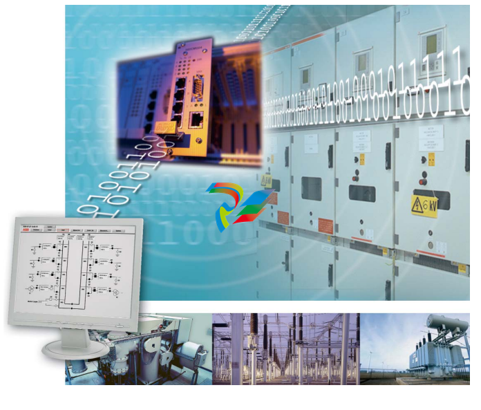
The Application Requirements
Transmission and distribution networks are frequently being expanded and reinforced,often resulting in more complex networks.This is valid for electrical transmission and distribution networks, as well as for gas,oil,water,wastewater and district heating grids. The task of monitoring and controlling the energy transportation in order to achieve an economical operation control requires an ongoing penetration of the grid down to the lowest levels
The increasing availability requirements of energy and its distribution and transportation also increases the demand of control systems.New and improved communication possibilities with higher transmission bandwidths and new transmission media allow telecontrol technology to mange this.
Continually increasing capabilities of decentralized control and closed-loop control solutions,based on higher performance microcontroller technology,also allows more functions to run directly in the station.This is valid not only for new remote stations,but also in stations which have to be upgraded due to a higher demand for information or station that need to be modernized due to age (retrofit).
In all cases,the telecontrol interface is the basic functional package.
The adaptation of new Intelligent Electronic Devices (IED) and expansion with application functions based on Programmable Logic Controller (PLC) solutions must also be possible.It is the task of modern RTU's to provide the right solution to these requirements.
The deregulation activities in the energy market, especially the metering tasks,requires more online information in order to control the energy flow and energy consumption.Municipal utility companies,responsible for the electrical,gas,water and wastewater grids,are moving towards controlling these networks in a more centralized fashion,i.e.in one central control center utilizing only one control system.This requires the different telecontrol communication links to be harmonized. The process data object model has to be coordinated between the different grid types
The standardization of telecontrol protocols and the increasing capabilities of communication networks makes this possible. A new RTU must be able to support demands of higher flexibility by adapting ANSI and IEC telecontrol protocol standards.The new RTU shall have the capacity to be connected to new communication media and digital communication networks.
• Usable for different applications
• Remote Control • Station Automation
• Communication Gateway
• Process-oriented configuration with open data exchange concept and MS-ExcelTM-Integration
• Integrated Human Machine Interface with basic monitoring and control functions
• No special tool for diagnoses required due to utilisation of web server technologies
• Programmable PLC functions • Support of standard transmission/communication protocols
• Events detection with a time resolution of 1 ms
• Real-time acquisition with DCF77,GPS,SNTP or IRIG-B
• Flexible system concept - scalable redundancy - scalable I/O - scalable communication
• High performance central processing units with 32-bit processor and multiple interfaces
• Distributed input/output units with high degree pre-processing functions
• Only a few types of different I/O modules
• Same I/O modules used in RTU200 and RTU232
• Applicable from medium voltage to highest voltage level
• Local presence of ABB in more than 50 countries
• 2'000 worldwide RTU560 installations per year, more than 10'000 RTU560 installations in total
• Security of investment • Step by step investment possible • Easy functional extension • Reduced engineering costs • Reduced engineering costs and no need of an additional monitoring and control system
• Reduced maintenance costs
• No need of an additional PLC system
• Communication with existing control systems and subordinated IEDs
• Precise analysis of disturbances
• Precise system wide analysis of network incidents
• Reduced investment costs
• High processing capacity and flexibility
• Reduced system costs
• Reduced maintenance and spare part costs
• Cost efficient migration to RTU560
• Reduced maintenance and spare part costs due to same hardware components
• Close to our customers all over the world
• Security of investment
The engineering work is an important cost factor that can be reduced by standardizing the process object model and ensuring that it supports stateof-the-art engineering tools.The engineering tool of the RTU must be able to perform the task of a single,stand-alone RTU,as well as be able to be integrated into an overall data engineering concept for a network control system. In addition to the basic functions,(i.e.data acquisition and control) modern telecontrol systems are required to provide a higher degree of functionality within the stations e.g.:
• High functional scope for telecontrol application functions
• Execute control and closed-loop applications using PLC capabilities
• Archive features to provide process data availability over longer periods for recovering or decoupling,e.g.the storing of disturbance files recorded by protection relays in an archive and analyzing them later,after transferring them to an Office PC
• Communication with multiple Network Control Centers (NCC).of process data filtering according to the demands of the NCC.Possible with different telecontrol protocols for each NCC
• Extended diagnosis functionality of the RTU equipment to reduce the costs for problem analysis and maintenance by accessing the information via Internet or Intranet options. This should be possible independent of the directly connected telecontrol links
• Interfacing various types of IEDs,such as digital protection relays or new transducers via fieldbus interfaces,etc
• Flexibility and space for future demands to extend the RTU for additional installed primary process units and/or higher demands in terms of control The architecture of a telecontrol system must be designed in such a way that it,thanks to its modularity and flexibility,can be adapted to the conditions and sizes of the different stations.It should also be open for later extensions of any type.
Our Solution for different Applications – the RTU560
ABB´s solution to different application requirements is the Remote Terminal Unit system RTU560. A key feature of the RTU560 concept is the extended possibility to integrate the various communication demands in a highly flexible and cost-optimized way.The capability of RTUs has increased significantly over the last few years.This has provided the opportunity to use remote terminal units for different applications.The RTU560 uses the same components to provide specific functions for the different applications.Since all applications are served out of the same product family a future upgrade to a different application is always possible. This goes in line with the ABB strategy to reuse I/O modules of ABB RTUs 200/232 for upgrading to RTU560. The various functional requirements can be grouped to the following three applications:
• Remote Control
• Communication Gateway
• Station Automation
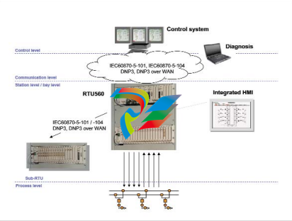
Remote Control One of the main tasks of the remote control application is the data collection
of hard wired information and provision of those to a higher level Control System. The RTU560
uses multi processor architecture to achieve high performance data processing. The scalable pl
atform,together with the modular IO-components guarantee the highest flexibility for different s
ignal appearance.The direct binary IO-interface for up to 110-220 V DC requires no additional int
erposing relays. The demand to communicate to various sub RTUs, IEDs and control centers is c
overed by the highly advanced communication capabilities.PLC-Functions according to IEC 611
31-3 enable the user to get automation functionality without using an additional product.
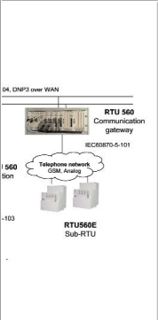
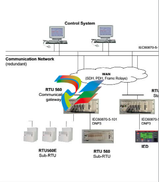
Communication Gateway The RTU560 with its highly sophisticated communication capabilities can also
be used as a communication gateway. By using TCP/IP networks and decentralized station communica
tion gateways,the complex frontend structures can be simplified. Shifting of centralized communicatio
n functions to station level utilizes the available bandwidth more efficiently and reduces the required c
ommunication lines at the same time. High availability is a common requirement today. The RTU560 a
ccommodates this with its decentralized structure compared to PCs or workstations. The flexible redu
ndancy concepts support different levels.The system approach of the RTU560 allows having redunda
nt power supplies,redundant communication lines and redundant communication modules accordin
g to the customer specific demand.A combination of the various redundancies is also possible.
For communication gateways,minimal engineering and implementation of standard and non standard protocols is crucial. The RTU560 with its open architecture and user friendly tools satisfies these requirements.
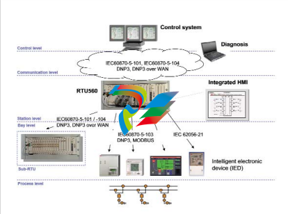
Station Automation The station automation application consists of interfaces to a mixture of protection and control equipment as well as metering devices and other automation products.The Human Machine Interface integrated into the RTU560 allows a basic local control and monitoring. Transmission of disturbance records and load profiles by using the communication network of the RTU560 are also available functions
Benefits:
• Cost optimized station automation with IEC 60870-5-103
• Data engineering for RTU and HMI in one step
• Use of the RTU560 communication network for disturbance data and load profiles
• Retrofit with digital bay controllers possible step by step
Flexible System Concept
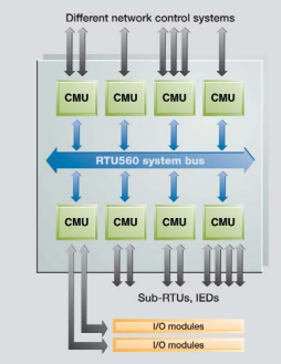
The software and hardware concept is based on
modularity. The software application tasks can be
organized in such a way as to be distributed over
different communication units (CMU boards).
This is possible due to an internal communication
concept that keeps all CMU boards informed about
the contents of the process data interface. There is
one process and system database which is available
in adapted copies for each CMU board.
The internal communication system ensures that
all process data are consistent. The different CMU
boards run the communication tasks for the
connected serial links. This allows the type and
number of different communication links running
on one CMU board to be defined.System performance is defined by the configuration of the CMU
boards.
The RTU560 is able to communicate with different hierarchical levels of a network control system, with subordinated RTUs or any other intelligent electronic devices (IEDs),or with the test and diagnostic system. The most important standard protocols supported by RTU560 for communication with the control system are:
• IEC 60870-5-101
• IEC 60870-5-104
• DNP 3.0 (also on ethernet)
• Modbus • RP 570/71
• Indactic 23/ 33/ 35
• TG 800 • Sinaut 8FW
• Conitel 300 For communication with subordinated RTUs and IEDs such as protection relays,local control units,etc.,the following protocols,among others,are available:
• IEC 60870-5-101
• IEC 60870-5-102
• IEC 60870-5-103
• IEC 60870-5-104
• DNP 3.0 • SPA-Bus
• Modbus
• RP570/71
• Indactic 21 The connection of the respective communication lines can be carried out in several ways:
• Direct links with RS 232-C interfaces (local communication)
• Voice-frequency telegraphy over leased telecommunication lines,private lines with narrow bandwidth modems or power line carriers
• Radio links
• Dial-up modem
• Fiber-optic cables
• Digital communication networks
With this concept the RTU560 fulfills the highest availability requirements. Technical features
• Redundant communication lines or links; communication via 2 communication lines in a parallel mode (multi host with all available protocols) or in an active/standby switchover mode (redundant line/network with IEC 60870- 5-101/104)
Time Synchronization The accuracy and resolution of the time stamp for a process event is important for analysing a process disturbance,especially when it is necessary to analyse events from and between different stations. The RTU560 meets this requirement.The internal time management is controlled by the CMU communication boards. The time resolution of the RTU560 is 1 ms for events,scanned by the directly connected I/O boards.Synchronization with absolute time can be achieved by one of the following four methods:
• Time synchronization by the network control center (NCC) via a periodically transmitted synchronization instruction with a communication protocol supporting this function
• Time synchronization using a real-time clock that receives the date and time from the GPS system
• Time synchronization using a real-time clock that receives date and time information from the DCF 77 time standard
• Time synchronization using SNTP V4 (RFC2030) on a LAN/WAN network The RTU560 time management system synchronizes the RTU with the supplied absolute time with a high degree of accuracy.The absolute accuracy is mainly provided by the source for synchronization used,whereby GPS and DCF 77 allow an accuracy of 5 ms and better.The accuracy of time synchronization by the NCC depends on transmission speed,and the method used within the NCC A time synchronized RTU560 can synchronize subordinate RTUs and IEDs via:
• a periodically transmitted synchronization instruction with a communication protocol supporting this function
• Time synchronization using SNTP V4 (RFC2030) on a LAN/WAN network Special hardware and software logic with a high control quality has been incorporated on each of the CMU communication boards to manage real time within the RTU560.Once the RTU560 is synchronized,the RTU560 can maintain a time accuracy of about 2 PPM,even if the time synchronization source is lost for a certain period.
Benefits:
• Excellent reliability in performance and communication
• High reliable remote control of important substations
• Reduction of service and maintenance cost
• Scalable redundancy and cost optimized concepts
Benefits:
• Flexible adaptation of time synchronization to system circumstances
• High time accuracy over the total network
RTU560 web server
Integrated Human Machine Interface For basic local monitoring and basic control an Human Machine Interface was integrated into the RTU560. The HMI-functionality itself is an integrated part of the RTU560 functionality;no additional SCADA product is needed.Single line pictures with active monitoring and control elements are stored on the CMU of the RTU560. Event and alarm lists are also available and exportable as CSV format for documentation. The data of the lists are stored on the flash which makes it power failure proof. The only software requirement for visualization on a PC is the Java Virtual Machine Freeware. The single line diagram allows an instant overview of the substation. The picture editor has a symbol library with predefined dynamic symbols. The picture editor contains different language and character sets. The component editor enables the user to create customer specific symbols in case they are not available in the standard libraries. The editor allows easy linking of dynamic symbols to the RTU560 runtime data to prevent engineering faults.Access authority for different users or groups together with command authority is essential for secure operation. Therefore this feature is also an integrated component of the RTU560.
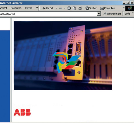
Diagnosis RTU560 diagnosis system is based on the web server technology. Therefore no special tools are required to analyse the RTU560.The diagnosis could be carried out either locally or remote via LAN/WAN. All RTU560 modules are maintenance free.Due to the small numbers of different modules,spare part stock is kept to a minimum.Since the application data is stored on Compact Flash CardsTM it is possible to exchange modules without new configuration download. The functional operation of the RTU560 is guaranteed by a comprehensive monitoring concept. The hardware and software is continuously monitored from the I/O boards throughout the entire RTU. The hardware and software monitoring is carried out by active checks at several levels. The diagnosis concept of the RTU560 is consequently adapted to the possibilities of modern communication.Once access to the RTU560 by Intranet has been established,all of the RTU560's relevant information can be read out from any location by a laptop. This system can be used for a checkup of the configuration or signal values and statuses. It allows service personnel to analyse and possibly solve a RTU problem from their office rather than making an unnecessary visit to the station. On the other hand,when travelling to the site is inevitable,the required spare parts can be determined beforehand. Remote access via Intranet is combined with authority privileges for the user.It is possible to:
• Monitor the RTU-produced internal error messages
• Monitor and check the RTU560 configuration and the status of all connected process signals
• Check the current version of the configuration file
• Down- or upload the RTU560 configuration file • Check and download revised software files for the RTU560 CMU boards
• Upload the archive files Access to each communication board is granted individually. The presentation of process information about statuses and values is presented in such a way that the service personnel are able to work with the same designations (object identification keys) as the operator in the control station.
The following data can be stored with time stamp:
• Process events of the RTU560 and connected subsystems (subordinate RTUs,IEDs,protection relays)
• Virtual data points (e.g.calculated values of PLC function)
• User login
• Commands
• System events and messages
• Analogue measured values
• Integrated totals (counter values)
• File archive (Load profiles of metering devices, Disturbance records of protection relays) The archive data are accessible via:
• Web server,front MMI (cable)
• Web server,TCP/IP channel (remote,WAN/LAN)
• CSV export (text file),Import in MS-ExcelTM
• Local print function to serial printer
• Data of the File archives are also accessible via file transfer
Local Print, Archive and File Upload The RTU560 is able to handle and file archive data which are protected against voltage loss (Compact Flash CardTM). The File archive can handle the following file types:
• Disturbance recorder files of connected protection relays/bay controller via IEC60870-5-103
• Disturbance recorder files of some connected protection relays/bay controller via SPABUS
• Load profiles of connected metering devices (e.g.IEC62056-21)
• Disturbance recorder of connected subordinated RTUs with IEDs are supported
• The upload to Flash memory is running automatically
Benefits:
• Archive data protected against voltage loss (non-volatile)
• Local or remote accessible via web server
• Easy engineering
• Buffer sizes are configurable
• Export function to MS OfficeTM
• Disturbance recorder files are available in standard COMTRADE format
• Automatic conversion to client naming structure
• No data loss of disturbance files on the protection relays because of limited memory
• Integrated component of the HMI
The data engineering of the RTU560 can easily be carried out by the user with the
help of the MS-WindowsTM based tool RTUtil 560 and by MSExcelTM signal lists.
RTUtil 560 is designed to engineer small RTU560, medium-sized RTU560 with a
set of included IEDs, and also to engineer router RTUs with all the types of commu
nication links and IEDs used in the customer's network.Process signal mapping to th
e different communication protocols is one of the main tasks needed in hierarchical co
mmunication network structures. The process signals of a small RTU connected at the
lowest level of a network may be routed via other RTUs on the way up to the final net
work control center (NCC). All necessary communication links and parameters are eng
ineered with RTUtil 560 in one project. The signal and communication data can be ent
ered into RTUtil 560 via import of MS-ExcelTM signal li
sts.Therefore only limited RTUtil 560 knowledge is required. The use of MS-ExcelTM f
unctionality allows quick and easy data entry of large volumes of process data.To allow
adaptations to specific customer or project requirements,the structure of the MS-Exc
elTM sheets used for data import is expandable and can also be used for documentatio
n. The Engineering principle in RTUtil 560 is according to IEC 613
46-1 standard.With the RTUtil 560, separate views for signals,hardware,and communic
ation data is possible.This makes configuration changes easy.Before generating configurat
ion files, the RTUtil 560 system carries out an engineering data consistency check. Any engi
neering errors occurring will be recognized and logged
in files with the error location. The configuration file transfer will be done by using the integra
ted web server connected to the RTU560 MMI interface. The configuration of the RTU560 can a
lso be carried out from a remote PC via Internet links or the customer's Intranet. Download by a n
etwork control center via IEC 60870-5-101/104 file transfer protocol is also possible.Upload of the data files is used for reverse data engineering
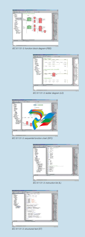
The RTU560 can optionally be equipped with a Programmable Logic Control (PLC) software package. This allows sequential control or closedloop application functions that are processed in parallel to the telecontrol activities. The PLC programming package fully complies to the IEC 61131-3 programming standard. The modularity of the RTU560 in hardware and software allows PLC programs to be run either on the same CMU central board,parallel to the telecontrol task, or on a separate CMU central board used only for the PLC application.PLC programs have access to all process signal values as well as the process signal qualifiers such as invalid,time,etc..PLC programs running distributed applications may use the qualifiers for secure and safe operation. PLC programs update the process signal values via the process data interface. The telecontrol task will be informed about changes and updates the new output values either to the process output boards or via the communication line to the network control centers and subdevices. PLC programs are developed by a powerful PLC programming tool MULTIPROG® wt. The PLC package allows programming in the programming languages defined in IEC 61131-3:
• Function Block Diagram (FDB)
• Ladder Diagram (LD)
• Sequential Function Chart (SFC)
• Instruction List (IL)
• Structured Text (ST)
The function block RTU library contains function
blocks to interface with the process I/Os values,
attributes and qualifiers. Additionally it is also possible to create user-specific function blocks or
functions for various applications.
Benefits:
• No need of additional PLC systems
• Flexible method to adapt to customer specific requirements
• Reduced education cost due to compatibility to IEC 61131-3 programming standard
-
 AEROTECH SM Series High-Performance Stepper Motors
 -
 AEROTECH BLMSC Series Linear Motors
 -
 AEROTECH Custom Linear Motors
 -
 AEROTECH BMS Series Brushless, Slotless Rotary Motors
 -
 AEROTECH BM Series Brushless Rotary Motors
 -
 AEROTECH BLMX Series Linear Motors
 -
 AEROTECH BLMH Series Linear Motors
 -
 AEROTECH BLM Series Linear Motors
 -
 AEROTECH BLMC Series Linear Motors
 -
 AEROTECH BLMUC-143 Linear motor forcer with thermistor
 -
AEROTECH BLMUC-111 Linear motor forcer with thermistor
-
AEROTECH BLMUC-95 Linear motor forcer with thermistor
-
AEROTECH BLMUC-79 Linear motor forcer with thermistor
-
AEROTECH BLMUC Series Linear Motors
-
 AEROTECH Automation1 FLEX Distributed Amplifier Multi-Axis Servo Control System
 -
 AEROTECH Automation1 HXA4 6-Axis Hexapod Servo Drive
 -
 AEROTECH Automation1 iHXA4 6-Axis Hexapod Servo Drive with Motion Controller
 -
 AEROTECH Modular System Control Console
 -
 AEROTECH TV Series Transformers
 -
 AEROTECH TM Series Transformers
 -
 AEROTECH UFM Noise Filter Module
 -
 AEROTECH MFM Motor Filter Module
 -
 AEROTECH MPG Handwheel Pendant
 -
 AEROTECH Automation1 Multi-Axis Joystick
 -
 AEROTECH ETM Enhanced Throughput Module
 -
 AEROTECH Automation1 XL4s High-Speed, Single-Phase Linear Servo Drive
 -
 AEROTECH Automation1 XL2e Enhanced, Compact Linear Servo Drive
 -
 Automation1 iXL2e Enhanced, Compact Linear Servo Drive with Motion Controller
 -
 AEROTECH Automation1 XL5e Enhanced, Linear Servo Drive
 -
 AEROTECH Automation1 iXL5e Enhanced Linear Servo Drive with Motion Controller
 -
 AEROTECH Automation1 GI4 Laser Scan Head Controller
 -
 AEROTECH Automation1 SI4 Stepper Interface
 -
AEROTECH Automation1 XI4 Servo Interface
-
 AEROTECH AEROTECH Automation1 iXI4 Servo Interface with Motion Controller
 -
 AEROTECH Automation1 XC6e Enhanced, High-Power PWM Servo Drive
 -
 AEROTECH Automation1 iXC6e Enhanced, High-Power PWM Servo Drive with Motion Controller
 -
 AEROTECH Automation1 XC2 Compact PWM Servo Drive
 -
 AEROTECH Automation1 XC4 PWM Servo Drive
 -
 AEROTECH Automation1 GL4 Galvo Laser Scan Head Linear Drive
 -
 AEROTECH Automation1 XC2e Enhanced, Compact Servo Drive with PWM+
 -
 AEROTECH Automation1 XC4e Enhanced, PWM Servo Drive
 -
 AEROTECH Automation1 XR3 Multi-Axis Servo Drive Rack
 -
 AEROTECH Automation1 iXR3 Multi-Axis Servo Drive Rack with Motion Controller
 -
 AEROTECH Automation1 iXC2 Compact PWM Servo Drive with Motion Controller
 -
 AEROTECH Automation1 iXC2e Enhanced, Compact PWM+ Servo Drive with Motion Controller
 -
 AEROTECH Automation1 iXC4 PWM Servo Drive with Motion Controller
 -
 AEROTECH Automation1 iXC4e Enhanced, PWM Servo Drive with Motion Controller
 -
 AEROTECH Automation1 iPC Industrial PC with Motion Controller
 -
 AEROTECH EPICS & TANGO Drivers for Distributed Control Systems
 -
 AEROTECH .NET, C, Python & LabVIEW APIs Custom Application Develotpmen
 -
 AEROTECH Automation1 Industrial Ethernet Support
 -
 AEROTECH Automation1 iSMC Intelligent, Software-Based Motion Controller
 -
 AEROTECH Automation1 iXA4 1- 2- or 4-Axis PWM Servo Drive with Motion Controller
 -
 AEROTECH Automation1 XA4 1- 2- or 4-Axis PWM Servo Drive
 -
 CTI 2500-ADP2-DISC Discrete Wiring Adapter for Series 500
 -
 CTI 2500-ADP1 Analog Wiring Adapter for Series 500
 -
 CTI 2500C-RADP-RS485 Remote Base Controller Adapter for Series 500
 -
 CTI 2500C-RADP-RBC Profibus RBC Adapter for Series 500
 -
 CTI 2500C-PADP-120V 120VAC 50W Power Supply for Series 500
 -
 CTI 2500-RADP RBC Adapter for Series 500
 -
 CTI 2500-R4500 520/530/DBC Adapter for Series 500 - MATURE
 -
 CTI 2500-PADP Power Supply Adapter for Series 500
 -
 CTI 2500-IADP I/O Adapter for Series 500
 -
 CTI 2500-VP15A-N4-W7 15" Flat-Panel PC with Windows® 7 Embedded
 -
 CTI 2500S-27-1750 Slice I/O, Ethernet, RS232/485. 900MHz, 2DIO / 4UAI / 2AI
 -
 CTI 2500S-26-1750 Slice I/O, Ethernet, RS232/485. 900MHz, 8DIO / 2UAI
 -
 CTI 2500S-23-1750 Slice I/O, Ethernet, RS232/485. 900MHz, 4DI / 4DO / 2UAI / 2AO
 -
 CTI 2500S-27-1550 Slice I/O, RS232/485. 2DIO / 4UAI / 2AI
 -
 CTI 2500S-26-1550 Slice I/O, RS232/485. 8DIO / 2UAI
 -
 CTI 2500S-23-1550 Slice I/O, RS232/485. 4DI / 4DO / 2UAI / 2AO
 -
 CTI 2500S-27-1050 Slice I/O, Ethernet, 2DIO / 4UAI / 2AI
 -
 CTI 2500S-26-1050 Slice I/O, Ethernet, 8DIO / 2UAI
 -
 CTI 2500S-23-1050 Slice I/O, Ethernet, 4DI / 4DO / 2UAI / 2AO
 -
 CTI 2500C-32F-CJC 32-Pin Field Wiring Connector with Cold Junction Compensation
 -
 CTI 2500C-32F 32-Pin Field Wiring Connector
 -
 CTI 2500C-8-TC Eight Thermocouple Inputs
 -
 CTI 2500C-8-RTD Eight RTD Inputs
 -
 CTI 2500C-8-RL-FC 8 Form-C Relay Outputs
 -
 CTI 2500C-8-IDO-24V 8 Isolated 24VDC Outputs
 -
 CTI 2500C-8-IDO-120V 8 Isolated 120VAC Outputs
 -
 CTI 2500C-16-DO-24V Sixteen 24VDC Digital Outputs
 -
 CTI 2500C-16-DO-120V Sixteen 120VAC Digital Outputs
 -
.png) CTI 500C-16-IDI-24V Sixteen Isolated 24V AC/DC Digital Inputs
CTI 500C-16-IDI-24V Sixteen Isolated 24V AC/DC Digital Inputs -
 CTI 2500C-16-IDI-120V Sixteen Isolated 120V AC/DC Digital Inputs
 -
 CTI 2500C-16-DIDO-SIM Sixteen Digital Input and Output SImulator
 -
 CTI 2500C-16-DI-24V Sixteen 24V AC/DC Digital Inputs
 -
 CTI 2500C-16-DI-120V Sixteen 120V AC/DC Digital Inputs
 -
 CTI 2500C-RBC-RS485 RS485 Remote Base Controller
 -
 CTI 2500C-RBC-PRF Profibus Remote Base Controller
 -
 CTI 2500C-PS-24V-35 35-Watt DC Power Supply
 -
 CTI 2500C-PS-120V-35 35-Watt AC Power Supply
 -
 CTI 2500C-R8 Eight-Slot Base
 -
 CTI 2500C-R4 Four-Slot Base
 -
 CTI 2500C-R16 Sixteen-Slot Base
 -
 CTI 2500C-2572-B Fast Ethernet TCP/IP Adapter
 -
 CTI 2500C-J750 Compact Janus PAC with 3MB Project Memory
 -
 CTI 2500C-C300 CPU with 512K User Memory
 -
 CTI 2500C-C200 CPU with 256K User Memory
 -
 CTI 2500C-C100 CPU with 128K User Memory
 -
 CTI 2500C-8-AO 8 Analog Outputs
 -
 CTI 2500C-8-AI 8 Analog Inputs
 -
 CTI 2559-FCAL Precision Calibration Connector
 -
 CTI 2559-FPC 40-Position Screw-Terminal Connector
 -
 CTI 2500-RFC PLC to RF Modem Cable
 -
 CTI 2500-40F 40-Position Standard Screw-Terminal Connector
 -
 CTI 2505 Vibration Sensor Interface Module
 -
 CTI 2554-A 4-Channel Isolated High Speed Counter Module
 -
 CTI 2553-A 2-Channel Mag Meter Input Module
 -
 CTI 2502 2-Channel High Speed Counter Input Module
 -
 CTI 2559-TC 8-Channel Thermocouple Input Module
 -
 CTI 2556-A 16-Channel Isolated Thermocouple Input Module
 -
 CTI 2556 16-Channel Isolated Thermocouple Input Module
 -
 CTI 2551-A 8-Channel Isolated Thermocouple Input Module
 -
 CTI 2559-RTD 8-Channel RTD Input Module
 -
 CTI 2557-A 16-Channel RTD Input Module
 -
 CTI 2557 16-Channel RTD Input Module
 -
 CTI 2552-A 8-Channel Isolated RTD Input Module
 -
 CTI 2534 8-Point Form-C Relay Output Module
 -
 CTI 2532 16-Point Form-A Relay Output Module
 -
 CTI 2531 32-Point Form-A Relay Output Module
 -
 CTI 2530 8-Point Form-C Relay Output Module
 -
 CTI 2562 8-Channel Analog Output Module
 -
 CTI 2560-A 8-Channel Isolated Analog Output Module
 -
 CTI 2501 8in/4out Analog Module
 -
 CTI 2558 8-Channel Analog Input Module
 -
 CTI 2555-A 16-Channel Analog Input Module
 -
 CTI 2550-A 8-Channel Isolated Analog Input Module
 -
 CTI 2599 8/16/32-Point AC Output Module


