
benderResidual current monitor RCMA475LY
Product description
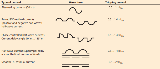
The AC / DC sensitive residual current monitor RCMA475LY is designed for monitoring earthed
power supply systems (TN and TT systems) where DC fault currents or residual currents continuously greater than zero may occur. These are in particular loads containing six-pulse
rectifiers or one way rectifiers with smoothing, such as converters, battery chargers, construction site equipment with frequency-controlled drives.
The prewarning stage (50 % of the set response value IΔn1) allow to distinguish between
prewarning and alarm. Since the values are measured with measuring current transformers,
the device is nearly independent of the load current and the nominal voltage of the system.
Application
• AC / DC sensitive residual current monitoring in earthed two, three or four conductor
systems.
• AC / DC sensitive current monitoring of single conductors de-energized under normal
conditions (e. g. N and PE conductors).
• Variable-speed drives
• Uninterruptible power supply systems (UPS)
Device features
• Internal measuring current transformer
ø 18 mm
• Two response values:
Alarm IΔn1: 30 mA…500 mA (0…700 Hz)
Prewarning IΔn2: 50 % / 100 % of IΔn1
• Adjustable response delay 0…10 s
(prewarning 0 / 1 s)
• Two separately adjustable alarm relays
with one changeover contact each
• N / O or N / C operation
• Fault memory
• Combined TEST and RESET button
• Connection external TEST and RESET
button
• LED bar graph indicator IΔn 0…100 %
• Connection external measuring instrument IΔn 0…100 %
• Sealable transparent cover
• Separate supply voltage
• Type B acc. to IEC 60755
Function
Residual current monitoring takes place via an internal measuring current transformer. When
the current respectively the residual current exceeds the set response value, the alarm LED
lights and the associated alarm relay switches when the set response delay has elapsed.
The alarm messages are stored. The fault memory can be reset by pressing the RESET button.
The device function can be tested using the TEST button.
The currently measured value in per cent related to the set response value is indicated on
the LED bar graph indicator.
Wiring diagram – system connection, external connections
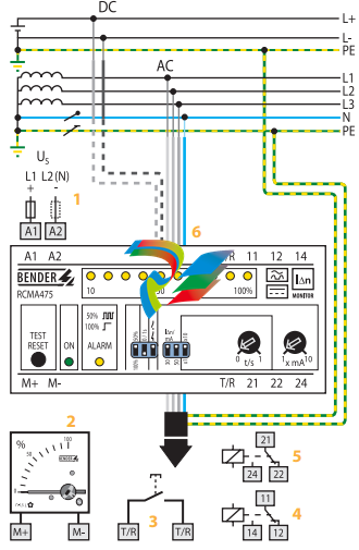
1 - Supply voltage US (see ordering information), a 6 A fuse recommended for line protection
2 - External measuring instrument
3 - External TEST and RESET button
4 - Alarm relay (alarm): switches when the fault current exceeds
the response value IΔn1.
5 - Alarm relay (prewarning): switches when the fault current
exceeds 50 % or 100 % of the response value IΔn1.
6 - Internal measuring current transformer
Do not route the PE conductor through the measuring current
transformer !
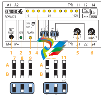
1 - Combined TEST and RESET button: short-time pressing (< 1 s)
= RESET, long-time pressing (> 2 s) = TEST.
2 - Power On LED: lights when the device is in operation and flashes
when the measuring range is exceeded.
3 - Alarm LED: lights when the fault current exceeds the set response value and flashes when 50 % of the set response value
are reached.
4 - LED bar graph indicator, shows the measuring value in per
cent related to the preset response value.
5 - Potentiometer for setting the response delay (0…1 s)
6 - Potentiometer for setting the response value (x 1…10 mA)
Setting of the DIP switches (white = switch position)
7 - Contact 21-22-24 (prewarning)
A - at 50 % of IΔn1
B - at 100 % of IΔn1
8 - Response delay prewarning
A - Delay 1 s
B - Delay 0 s
9 - Alarm relay
A - N / O operation
B - N / C operation
10 - Response range
A - 30 mA x 1…10 B - 50 mA
11 - Response delay
A - Setting value t
/s x10
B - Setting value t
/s x1
Technical data residual current monitor RCMA475LY
Insulation coordination acc. to IEC 60664-1
Rated insulation voltage AC 250 V
Rated impulse voltage / pollution degree 4 kV / 3
Voltage ranges
Supply voltage US see ordering information
Operating range of US 0.85…1.1 x US
Frequency range of US DC / 50…60 Hz
Power consumption ≤ 3.5 VA
Measuring circuit/response values
Internal measuring current transformer ø 18 mm
Operating characteristic acc. to IEC 60755 Type B
Rated residual operating current IΔn2 (prewarning) 50 / 100 % of IΔn1
Response delay tv 0 / 1 s
Rated residual operating current IΔn1 (alarm) 30…500 mA
Response delay tv, adjustable 0…10 s
Rated frequency 0…700 Hz
Relative percentage error 0…- 25 %
Hysteresis approx. 25 % of the response value
Response time tan at IΔn1 = 1 x IΔn1 / 2 (tv = 0 s) < 70 ms
Response time tan at IΔn1 = 5 x IΔn1 / 2 (tv = 0 s) < 40 ms
Displays
LED bar graph indicator 0…100 %
LEDs Power On, prewarning, alarm
Inputs / outputs
TEST and RESET button internal / external
Cable length external TEST and RESET button ≤ 10 m
Current source for external measuring instrument 0…100 % DC 0…400 μA
Load ≤ 12.5 kΩ
Switching elements
Number of switching elements 2 x 1 changeover contact
Operating principle, adjustable N / C operation / N / O operation
Electrical endurance, number of cycles 12000
Rated contact voltage AC 250 V / DC 300 V
Limited making capacity AC / DC 5 A
Breaking capacity 2 A, AC 230 V, cos phi = 0,4
0.2 A, DC 220 V, L / R = 0.04 s
Fault memory ON
General data
EMC immunity acc. to EN 61543
EMC emission acc. to EN 61000-6-4
Shock resistance IEC 60068-2-27 (during operation) 15 g / 11 ms
Bumping IEC 60068-2-29 (during transport) 40 g / 6 ms
Vibration resistance IEC 60068-2-6 (during operation) 1 g / 10…150 Hz
Vibration resistance IEC 60068-2-6 (during transport) 2 g / 10…150 Hz
Ambient temperature, during operation - 25 °C…+ 70 °C
Ambient temperature, when stored - 40 °C…+ 75 °C
Climatic category IEC 60721-3-3 3K5
Operating mode continuous operation
Mounting any position
Connection screw terminals
Connection properties
rigid / flexible 0.2…4 / 0.2…2.5 mm2
flexible with ferrules without / with plastic collar 0.25…2.5 mm2
Conductor sizes (AWG) 24…12
Protection class, internal components (IEC 60529) IP30
Protection class, terminals (IEC 60529) IP20
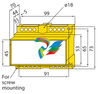
Type of enclosure X475
Enclosure material polycarbonate
Screw mounting 2 x M4
DIN rail mounting acc. to IEC 60715
Flammability class UL94V-0
Standards IEC 62020
Instruction leaflet BP404001
Weight ≤ 350 g
Accessories
Conditions of operation according to IEC 62020, IEC 60755 amendment 2, Type B
Dimension diagram X475
Dimensions in mm

-
 Beckhoff C6640-0040 Control Cabinet Industrial PC 7-Slot
 -
 BECKHOFF CONTROL CABINET INDUSTRIAL PC - C6930-1062-0050
 -
 Beckhoff Automation EtherCAT Terminal EK1100 EK1122
 -
 Beckhoff CP6533-0001-0060 IPC
 -
 Beckhoff EK9500 | EtherNet/IP™ Bus Coupler
 -
 Beckhoff CP6202-1047-0050 - An industrial-grade embedded panel computer.
 -
 Beckhoff C6650-0040 Industrial PC
 -
 BECKHOFF CX5230-0185 / 000119805 PLC Module
 -
 BECKHOFF EL4732 | EtherCAT Terminal, 2-channel analog output, voltage, ±10 V, 16 bit, oversampling
 -
 Beckhoff CP6202-0001-0010 Economy Built-In Panel
 -
 Beckhoff AX5206-0000-0202 Digital Compact Servo Drives 2-channel
 -
 Beckhoff CP6606-0001-0020 7-inch Economy Panel PC
 -
 Beckhoff CPU basic module CX2020-0155 + power supply module CX2100-0004
 -
 Beckhoff CP2913-000 Multi-Touch Display
 -
 Beckhoff CP6500-1012-0060 14250369 Control Cabinet
 -
 Beckhoff CP7902-0001-0000 Economy Control Panel with DVI/USB Extended interface
 -
 Beckhoff C6920-0010 Control cabinet Industrial PC
 -
 BECKHOFF C3640-0050 Build-in Industrial PCs
 -
 Beckhoff KL6023-0000 KL6023 EnOcean Wireless-Adapter
 -
 Kollmorgen AKM54G-ANC2DB00 servo motor
 -
 Kollmorgen AKD-P00606-NBCN-0000 Servo Drive
 -
Kollmorgen S200 Series S20350-VTS SERVO DRIVE
-
 KOLLMORGEN AKD-P00606-NBCC-I000 SERVO DRIVE
 -
 Kollmorgen MV65WKS-CE310/22PB Servo Drive Control Module
 -
 Kollmorgen S20360-VTS-021 Servo Drive
 -
 KOLLMORGEN CR06550 High-precision digital servo amplifier
 -
 KOLLMORGEN DBL5N01050-03S-VV0-S40 3-Phase AC Synchronous Brushless Servo Motor
 -
 KOLLMORGEN S70301-NANANA-024 SERVO DRIVE
 -
 Kollmorgen S20360-VTS S200 Series Servo Drive
 -
 Kollmorgen RBE-03011-A00 Brushless Frameless Servo Motor
 -
 KOLLMORGEN AKD-T00306-NBAN-0000 INPUT SERVO DRIVE
 -
 KOLLMORGEN S700 Servo Controller S70302-NANANA
 -
 Kollmorgen AKD-P00607-NBEC-0000 400/480VAC 4.40KVA Servo Drive.
 -
 KOLLMORGEN S70102-NANANA SERVO DRIVE
 -
 KOLLMORGEN AKM21E-ANSNEH02 PM Servo Motor & PRD-AMPE25EB-00 Servo Drive Array
 -
 KollMorgen SC1R06260 Servo Drive 1.4/2.2 KVA 115230 Vac
 -
 Kollmorgen AKD-P00306-NBAN-0000 Servo Drive
 -
Kollmorgen TTB2-2042-3052-A DC Motor Industrial Drive 5.5A 185 oz/in
-
 KOLLMORGEN SERVOSTAR 610-AS SERVO AMPLIFIER_SERVOSTAR610AS_S61001
 -
 KOLLMORGEN PRD-0016400P-10 & PRD-0016600D-30 Axis Control System Modules
 -
KOLLMORGEN Seidel DBL5N01700-03S-000-S40 Servo Motor
-
 Hirschmann RS20-1600M2T1SDAEHH03.1.02 Rail Switch
 -
 Hirschmann BRS30-24TX Industrial Rail Switch
 -
 Hirschmann RSPM20-4T14T1EV9HHS999.9.99 Managed Ethernet Switch
 -
 Hirschmann BELDEN RS40-0009CCCCSDAPHH09.0.14 / RS400009CCCCSDAPHH09014
 -
Hirschmann RS40 Rail Switch RS40-0009CCCCSDAE
-
 Hirschmann BELDEN RS30-0802T1T1SDAP / RS300802T1T1SDAP Fully Managed Layer 2 Compact Rail Switch
 -
 Hirschmann BELDEN RS20-0800M2M2SDAUHH / RS200800M2M2SDAUHH
 -
 Hirschmann EAGLE30-04022O6TT999SCCY9HSE3F Industrial Firewall Router Switch
 -
 Hirschmann RS20-1600T1T1SDAEHH09.0.14 RS20 Rail Mount Ethernet Switch
 -
 Hirschmann EAGLE0200T1T1TDDY90000HHE05.3.03 Industrial Security Router
 -
Hirschmann - BELDEN MIPP-AD-1L9P
-
 HIRSCHMANN RSPM20-4Z64Z6TV9HHS9 942 106-999 RAIL SAFETY SWITCH
 -
 HIRSCHMANN FIBEROPTIC MODULE FIP P/N: OZDFIPG3T
 -
 HIRSCHMANN RS20-1600M2M2SDAUHH Ethernet rack-mounted switch
 -
 HIRSCHMANN BELDEN RS20-0400T1T1SDAEHH04.0.01 / RS200400T1T1SDAEHH04001
 -
HIRSCHMANN MM2-4FXM3 MICE Media Module
-
HIRSCHMANN RS20-0800M2M2SDAE Industrial Ethernet Rail Switch
-
 Hirschmann RS20-2400T1T1SDAP / RS20-2400T1T1SDAPHH05.0.02
 -
 GE MLJ1005B010H00C MLJ Digital Synchromism Check
 -
 ALSTOM MICROTECH DX21-M2 Digital Excitation Controller
 -
HIRSCHMANN BRS20-1200ZZZZ-STCY99HHSES
-
 HIRSCHMANN MM3-4FXM2 MICE Media Module
 -
Hirschmann RSB20-0800T1T1SAABHH 8Port ENet Rail Switch RSB20
-
 Hirschmann MACH102-8TP Ethernet Switch
 -
 SAACKE DDZ-M marine steam pressure atomizer
 -
 SAACKE SKV-A marine rotary cup atomizer
 -
 SAACKE Seavis HMI05e
 -
 Kollmorgen MMC-SD-2.0-230 Servo Drive 100-240VAC 2KW 10A Output 3PH 100-240VAC
 -
 Kollmorgen Servo drive CR10550
 -
 Kollmorgen AKD-P01207-NACN-0054 Servo Driver
 -
 Kollmorgen S406M-CA-036 Servostar
 -
.png) Kollmorgen AKD-B02407-NAAN-0000 Digital Servo Drive
Kollmorgen AKD-B02407-NAAN-0000 Digital Servo Drive -
 Kollmorgen SERVOSTAR S406AM-CA Digital Servo Drive
 -
 KOLLMORGEN SERVOSTAR 603-AS SERVO AMPLIFIER_SERVOSTAR603AS_S60301
 -
Kollmorgen S700 Servo Controller (S70602-NANANA-NA)
-
 Kollmorgen MPK411 controller
 -
 KOLLMORGEN MMC-SD-1.3-460-D Smart Drive
 -
 KOLLMORGEN AKM21C-CKB2AA-00 / AKM21CCKB2AA00 Servomotor
 -
 BECKHOFF AX5106-0000-0200 | Digital Compact Servo Drives 1-channel
 -
 BECKHOFF C3620-0000 INDUSTRIAL COMPUTER (MOTORSHELVES)
 -
 Beckhoff EK1960-0000 TwinSAFE Compact Controller
 -
 Beckhoff C6930-0050 Control Cabinet Industrial PC
 -
 Beckhoff CP7711-0001-0030 Industrial Computer Detection
 -
 Beckhoff CX1001-0111 Embedded PC CPU Module
 -
 Beckhoff C6017-0020 | Ultra-compact Industrial PC
 -
 Beckhoff EK1322 | 2-port EtherCAT P junction with feed-in
 -
 Beckhoff CP2219-0010 Panel
 -
 BECKHOFF C6015-0020 ULTRA COMPACT INDUSTRIAL PC
 -
 BECKHOFF CX2030-0120/Standard CPU Module Embedded PC Windows PLC controller
 -
 Beckhoff CP7721-1090-0020 Panel PC
 -
 Beckhoff PC CPU Module CX5130-0175
 -
 Beckhoff C6920-0050 Control Cabinet
 -
 Beckhoff EL6631 EtherCAT 2-Port Communication Interface, Profinet RT Controller
 -
 Beckhoff CP6202-0001-0060 touch screen panel PC
 -
 Beckhoff CP3916-1002-0000 Multi-Touch Control Panel
 -
 Beckhoff EP1809-0021 | EtherCAT Box, 16-channel digital input, 24 V DC, 3 ms, M8Preferred type
 -
 Beckhoff CX8190 PLC Embedded Industrial PC Ethernet Controller
 -
 Beckhoff CX2100-0914 Power Supply for External
 -
 Beckhoff Automation CP6906-0001-0000 HMI
 -
 Beckhoff EP7342-0002 Module
 -
 Beckhoff CX1020-0112 / CX1100-0910 / CX1020-N010 / CX1100-0003 Windows CPU
 -
 Beckhoff EP7211-0034 EtherCAT Box 1 Channel Motion Interface
 -
 Beckhoff C6240-0030 Control cabinet Industrial PC
 -
 beckhoff motherboard CB1052-0004 CB1052-0004
 -
 Beckhoff AX2006-AS Servo Drive / Variable Frequency Drive
 -
BECKHOFF CP6207-0001-0020 NSMP
-
 Beckhoff C6930-1142-0060 Industrial Computer
 -
 Beckhoff FC7501-0000 interface card
 -
 Beckhoff CX5140-0175 Embedded PC PLC CPU CX5140 Industrial Controller
 -
 Beckhoff CP7802-1100-0010: High-End IP65 Control Panel with DVI/USB Extended Interface
 -
BECKHOFF CP3716-1058-0010 CONTROL PANEL
-
 Beckhoff AX8108-0000 Single-Axis Module
 -
 Beckhoff CU8851-0000 | USB extension, USB Extended 2.0 receiver box
 -
Beckhoff C6017-0030 | Ultra-compact Industrial PC
-
 Beckhoff CX1001-0120/CX10010120.cx1000-n001.cx1000-n000 System Overview
 -
 Beckhoff CPU Module CX5140-0155/4GB CPU Module
 -
 Beckhoff CP6533-0001-005: Built-in Panel PC with High-Definition Multi-Touch Control
 -
 Beckhoff EL5042 | EtherCAT Terminal, 2-channel encoder interface, BiSS® C
 -
 Beckhoff C6920-1080-0040: Premium Control Cabinet Industrial PC
 -
 Beckhoff C6920-0060 | Control cabinet Industrial PC
 -
 Beckhoff Embedded-PC CX5010-1121
 -
 Beckhoff CB3050-0010 Mainboard Motherboard
 -
 Beckhoff PLC module CX1020-0000 Basic CPU module (service phase)
 -
 Beckhoff CP7812-1056-0010 15" Multitouch Display Control Panel
 -
 Beckhoff CX5120-0115 /2GB Controller Module
 -
 Beckhoff CP7201-1000-0000 Industrial Panel PC
 -
 Beckhoff Servo Motor AM8061-0JH1-0000


