
METRIXHIGH TEMPERATURE VELOCITY TRANSDUCER
1. PURPOSE PURPOSE
The purpose of this safety manual is to establish the safety aspect of the Metrix - 5845C High Temperature Velocity
transducer and to enable the integration of this device into a safety related system, with the objective to be in compliance
with the requirements of the IEC 61508-2 Annex D. The information contained in this Safety Manual are valid for the model
indicated in the paragraph 4.1.
When the 5845C High Temperature Velocity transducer is in included in a Safety Instrumented Function, the integrator shall
evaluate the performance of the device into the SIF loop, in order to ensure its proper implementation.
2. TERMS, DEFINITIONS AND A TERMS, DEFINITIONS AND ABBREVIATIONS REVIATIONS REVIATIONS
2.1. TERMS AND DEFINITIONS TERMS AND DEFINITIONS
Architecture
Arrangement of hardware and/or software elements in a system.
Architectural constraint
This reports the maximum SIL achievable based on the SIF’s subsystems architecture alone. This is calculated solely on
the basis of Type A or Type B device selection, redundancy (hardware fault tolerance), and the safe failure fraction
(calculated or conservatively assumed if no data is provided). It does not pertain to Systematic Capability or
certification. This is calculated as indicated, using respective IEC 61508 or IEC 61511 tables.
Architectural Type
- Type A equipment or (sub)system: “Non –complex” (sub)system or equipment according 7.4.3.1.2 of IEC 61508-2;
- Type B equipment or (sub)system: “Complex” (sub)system or equipment according 7.4.3.1.3 of IEC 61508-2.
Diagnostic Coverage
Fraction of dangerous failures rates detected by diagnostics. Diagnostics coverage does not include any faults detected
by proof tests.
Mean Repair Time
Expected overall repair time
Mean Time to Restoration
Expected time to achieve restoration.
Mode of operation
Way in which a SIF operates which may be either low demand mode, high demand mode or continuous mode:
• Low Demand Mode: mode of operation where the SIF is only performed on demand, in order to transfer the
process into a specified safe state, and where the frequency of demands is no greater than one per year;
• High Demand Mode: mode of operation where the SIF, is only performed on demand, in order to transfer the
process into a specified safe state, and where the frequency of demands is greater than one per year;
• Continuous Mode: where the mode of operation where the SIF retains the process in a safe state as part of normal
operation.
MooN
SIS, or part thereof, made up of “N” independent channels, which are so connected, that “M” channels are sufficient to
perform the SIF.
Hardware Fault Tolerance
A hardware Fault Tolerance of N means that N+1 is the minimum number of faults that could cause a loss of the safety
function. In determining the hardware fault tolerance no account shall be taken of other measures that may control the
effects of faults such as diagnostics.
Probability of dangerous Failure on demand PFD
Average probability of dangerous failure on demand.
Probability of dangerous Failure per Hour PFH
Average probability of dangerous failure within 1 h.
Proof Test
Periodic test performed to detect dangerous hidden faults in a SIS so that, if necessary, a repair can restore the system
to an “as new” condition or a close as practical to this condition.
Safe Failure Fraction
Property of a safety related element that is defined by the ratio of the average failure rates of safe plus dangerous
detected failures and safe plus dangerous failures.
Safety instrumented function (SIF)
Safety Function to be implemented by a safety instrumented system (SIS)
Safety instrumented system (SIS)
Instrument system used to implement one or more SIFs.
Safety Integrity
Ability of the SIS to perform the required SIF as and when required.
Safety Integrity Level (SIL)
Discrete level (one out of four) allocated to the SIF for specifying the safety integrity requirements to be achieved by
the SIS.
Safe State
State of process when safety is achieved.
Systematic Capability
Measure (expressed on a scale of SC 1 to SC 4) of the confidence that the systematic safety integrity of a device meets
the requirements of the specified SIL, in respect of the specified safety function, when the device is applied in
accordance with the instructions specified in the device safety manual.
λ
Failure rate (per hour) of a channel in a subsystem.
λD
Dangerous failure rate (per hour) of a channel in a subsystem.
λS
Safety failure rate (per hour) of a channel in a subsystem.
λDU
Dangerous undetected failure rate (per hour) of a channel in a subsystem.
λDD
Dangerous detected failure rate (per hour) of a channel in a subsystem.
functional safety
part of the overall safety relating to the EUC and the EUC control system that depends on the correct functioning of the
E/E/PE safety-related systems and other risk reduction measures
safe state
state of the EUC when safety is achieved
The Metrix 5485C is a moving-coil velocity transducer, specifically designed for continuous use
in elevated temperatures. A permanent magnet moving back and forth within a coil winding
induces and electromagnetic field in the windings. This electromagnetic field is proportional to
the velocity of oscillation of the magnet: the magnet shall be mounted on the vibration object
to measure its velocity.
A zero-friction coil suspension provides accurate, repeatable vibration measurements over a
wide range of amplitude and frequency and is built to withstand the high-g environments and
cross-axis vibrations typical of gas turbines. The coil bobbin is suspended by two non-twisting, circular spider springs that
provide a clean frequency response.
Purely viscous electromagnetic damping is employed and eliminates friction-prone air damping. This allows improved
detection of small vibration amplitudes at low frequencies.
The sensor is available in two configurations: with integral armored cable or removable armored cable via a 2-pin MIL-style
threaded connector. The case is constructed of stainless steel and its robust internals are hermetically sealed to ensure
durability in the most hostile environments. The product is approved for use in Zone 2 / Div 2 hazardous areas without use
of intrinsic safety barriers. It is also approved for use in Zone 0/1 and Div. 1 areas with use of an appropriate intrinsic safety
barrier.
The Metrix 5485C Velocity Sensor shall be used in application where there is a continuous vibration of the unit to be
supervised and where the target is the vibration detection over the assigned threshold.
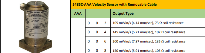
PRODUCTS FAMILY PRODUCTS FAMILYIDENTIFICATION IDENTIFICATION IDENTIFICATION
This Safety Manual is valid for each product listed in this paragraph. In the following table are listed the family models for
the sensor 5485C with Removable Cable. Each sensor is differentiated one from the other by the internal coil resistance: the
latter allows a differential measure sensitivity.
SAFETY PARAMETERS SAFETY PARAMETERS
Specific activities necessary to investigate and reach a judgment on the adequacy of the functional safety achieved by the
E/E/PE safety-related system or compliant items (elements/subsystems) has been conducted by an independent assessor.
The following failure rates data shall be used to the PFDAVG estimation, taking into consideration all parameters such as
redundancy, architectural constraints, diagnostic capability, also introduced by the whole system, including the
considerations about the proof test and its effectiveness, mean time of restoration, up to the maintenance capability and its
minimum characteristics.
NOTICE
The design of each Safety Instrumented Function shall meet the requirements listed in the reference
standards that shall be selected by taking into account the specific application.
The estimated safety integrity, for each safety function, due to random hardware failures (including soft-errors) and random
failures of data communication processes. The following table shows the failure rates of the device listed in para. 4.1.
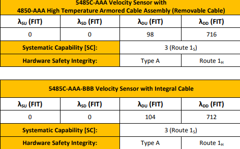
NOTICE
The failures rates are distributed considering the ability of the SIS logic solver to detect short circuit and
open circuit, as described in para. 7.
REQUIREMENTS FOR IMPLEMENTATION INTO A SIS REQUIREMENTS FOR IMPLEMENTATION INTO A SIS
The SIS logic solver shall be able to detect the sensor fault through its signal. The most critical failure modes, open circuit and
short, give as a result an output signal equal to zero.
The logic solver used to acquire the 5485C output signal shall have a high internal impedance (not less than 100kΩ).
In order to maintain the safety capability of the sensor, the logic solver shall activate a proper feedback when a zero-voltage
signal is detected. This proper feedback shall be used as fault condition of the sensor. The fault condition shall be properly
managed as per each specific safety function.
NOTICE
The sensor isn’t designed to impulsive vibration. It shall be used in application having a natural vibration
frequency in the range of the sensor in order to allow a proper diagnostic of the correct functionality of the
sensor.
NOTICE
The natural vibration of the equipment under control shall not exceed the transducer maximum
displacement of 1,8mm (70 mils).
After the first installation, and after any replacing or proof test, the right functionality of the sensor through verifying of coilto-case insulation. The electrical test shall be used to discover possible wire damage able to increase the resistance of the
connecting cable.
PROOF TEST PROOF TEST
The proof test is not necessary, since for the entire lifetime, the correct functioning according to the specifications indicated
in the para. 4.2 are satisfied. However, the proof test can be performed in order to satisfy the requirement coming from the
demand rate of the Safety Instrumented Function, where the Metrix 5845C is involved.
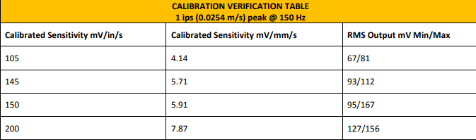
SENSOR VERIFICATION CALIBRATION PROCEDURE
Mount the 5845C on a shaker table and verify the RMS output per table below. The table is divided according to the
different types of Sensitivity.
NOTICE
The test detailed in this paragraph shall be carried out by competent and trained personnel.
WARNING!
Maintenance may compromise the sensor. Follow the instruction listed into the user manual is mandatory
to ensure the correct operability of SIS.
-
 HIRSCHMANN MSM20-M2M2M2M2SY9HH9E Ethernet media modul
 -
 HIRSCHMANN SPIDER-PL-20-05T1999999TWVHHHH Industrial Ethernet Rail Switch
 -
 Hirschmann SPIDER-PL-20-07T1M2M299TWVHHHH Industrial ETHERNET Rail Switch
 -
.png) Hirschmann (Belden) RS20-1600M2M2SDAEHC09.1.00 DIN-rail managed industrial Fast Ethernet switch
Hirschmann (Belden) RS20-1600M2M2SDAEHC09.1.00 DIN-rail managed industrial Fast Ethernet switch -
 Hirschmann (Belden) RS30-1602O6O6TDAPHC09.1.00 DIN-rail managed industrial Ethernet switch
 -
 Hirschmann (Belden) RS30-2402O6T1SDAPHH09.0.13 DIN-rail industrial Ethernet switch
 -
Hirschmann (Belden) SPIDER-PL-20-04T1S29999TY9HHHH Ethernet DIN-rail switch
-
 HIRSCHMANN RS20-1600T1T1SDAUHX Switch
 -
 HIRSCHMANN BRS42-0012OOOO-SPCZ99HHSES industrial switch
 -
 Hirschmann RS20-0800S2S2TDHPHH09.0.14 Fast Ethernet DIN rail switch.
 -
 HIRSCHMANN MM20-Z6Z6M2M2SAHH Hybrid Fast Ethernet Media Module
 -
 HIRSCHMANN MM20-Z6Z6T1T1SAHH hot-swappable hybrid Fast Ethernet Media Module
 -
 HIRSCHMANN MM20-P9P9T1T1SAHH Hybrid Fast Ethernet Media Module
 -
 HIRSCHMANN MM20-M4T1T1T1SAHH Hybrid Fast Ethernet Media Module
 -
 HIRSCHMANN MM20-M4M4T1T1SAHH Hybrid Fast Ethernet Media Module
 -
 HIRSCHMANN MM20-M2M2M2M2SZHH Ethernet media module
 -
HIRSCHMANN MM20-M2M2M2M2SAHH Ethernet media module
-
 HIRSCHMANN MM20-T1T1T1T1EBH 4-port Fast Ethernet Copper Cable Media Module
 -
HIRSCHMANN MM20-T1T1T1T1SAHH 4-port Fast Ethernet Copper Cable Media Module
-
HIRSCHMANN MM20-T1T1T1T1SAHH 4-port Fast Ethernet Copper Cable Media Module
-
 HIRSCHMANN MM20-Z6Z6EBH Hot-swappable fast Ethernet media module
 -
 HIRSCHMANN MM20-Z6Z6SAHH Ethernet media module
 -
HIRSCHMANN MM20-Z6Z6Z6Z6EBH Industrial Media Module
-
 MSM40-T1T1T1TZ9HH9E99.9.99 HIRSCHMANN Switch
 -
 HIRSCHMANN MS20-0800SAAEHC / MS20-0800SAAEHC0 8-port modular Layer 2 management Ethernet switch
 -
 Hirschmann RSPM20-4T14T1SZ9HHS9 Switch RSPM20-4T14T1SZ9HHS9
 -
 HIRSCHMANN RS20-1600M2M2SDAEHH09.1. RS20/30/40 Managed Switch configurator
 -
HIRSCHMANN RS20-1600M2M2SDAEHX09.0.00 Ethernet switch
-
 HIRSCHMANN BELDEN SPIDER-PL-20-07T1M2M299TY9HHHH / SPIDERPL2007T1M2M299TY9HHHH
 -
HIRSCHMANN MM3-1FXS2/3TX1 Switching Board Module
-
 HIRSCHMANN RSPE30-24044O7T99-ECCP999HHSE2A08.1.00 Industrial-grade fanless management-type Ethernet switch
 -
 HIRSCHMANN RS30-1602OOZZSDAEHC09.1.00 DIN-rail-mounted managed Layer 2 Ethernet switch
 -
 HIRSCHMANN MACH104-20TX-F Managed 24-port Full Gigabit 19" Switch
 -
 HIRSCHMANN Switch RS20-0800M4M4SDAE
 -
Hirschmann RS30-1602O6O6SDAEHH09.1. Management-type Ethernet switch
-
 Hirschmann RS30-1602OOZZSDAEHC09.0.10 Open rack-style Ethernet switch
 -
 HIRSCHMANN RSPE30-24044O7T99-SCCV999HHSI2SXX.X.XX High-Availability Seamless Redundancy
 -
HIRSCHMANN RSPE30-24044O7T99-SCCZ999HHSE2A DIN-rail Ethernet switch
-
HIRSCHMANN MM2-4TX1-EEC switch
-
HIRSCHMANN MSM40-T1T1T1T1TZ9HH9E99.9.99 Module
-
 HIRSCHMANN RS20 Rail Switch RS20-0400S4T1SDAEHC07.1.01
 -
 HIRSCHMANN M4-FAST8-SFP Fast Ethernet media module
 -
 HIRSCHMANN RS20-0400M2T1SDAP Managed Fast-Ethernet-Switch
 -
 HIRSCHMANN BELDEN SPIDER II 8TX/1FX EEC Industrial Ethernet Rail Switch
 -
HIRSCHMANN MM3-2FXS2/2TX1
-
 HIRSCHMANN RS2-4TX/1FX EEC Industrial Ethernet Rail Switch
 -
 RS30-0802O6O6SDAEHC09.0.10 HIRSCHMANN Switch
 -
 HIRSCHMANN m4-8TP-RJ45 Ethernet Media Module
 -
 HIRSCHMANN MSP30-24040SCZ9URHHE3A switch
 -
 Hirschmann rack MS30-1602SAAPHC
 -
 HIRSCHMANN RS2-FX/FX Industrial Switch Module
 -
Rs1txfx - Hirschmann - Rs1-Tx/Fx Rail Switch
-
RS20-0800S2S2SDAEHC09.1.00 HIRSCHMANN Commutator
-
 Hirschmann EAGLE20 TX/TX Industrial Security Router
 -
 Hirschmann SPIDER-SL-20-04T1S29999SY9HHHH Industrial Switch
 -
 HIRSCHMANN MAR1040-4C4C4C4C9999SMMHRHHXX.X. Gigabit Ethernet Switch configurator
 -
 Hirschmann MAR1040 Industrial Switch
 -
 HIRSCHMANN BELDEN RS30-1602O6O6SDAE
 -
Hirschmann RS20-1600M2M2SDAUHC Ethernet DIN rail switch
-
 HIRSCHMANN OCTOPUS 24M industrial switch
 -
 HIRSCHMANN RS20-1600T1T1SDAE Management-type Ethernet switch
 -
 HIRSCHMANN RS20-1600T1T1SDAUHH industrial switch
 -
HIRSCHMANN RS20-0800M2M2SDAPHC09.0.04 switch
-
 Hirschmann MR 8-03 24V DC Industrial Modular Bridge/Router
 -
 HIRSCHMANN RS20-0400M2T1SDAPHC08.0.01 Managed Switch
 -
 MACH1130 Hirschmann Industrial Switch
 -
 HIRSCHMANN 943824-002 SPIDER 5TX Industrial Ethernet Switch
 -
 HIRSCHMANN RS30-0802O6O6SDAEHC09.1.00 Managed Industrial Switch
 -
 HIRSCHMANN RS20-0400M2M2TDAEHC04.0.01 Industrial Switch
 -
 HIRSCHMANN BRS20-0600Z6Z6-STCZ99HHSES Industrial Switch
 -
 HIRSCHMANN MACH104-20TX-FR-L3P Industrial Ethernet Switch
 -
 HIRSCHMANN RS40-0009CCCCEDBPHH06.0.01 Industrial Switch
 -
 HIRSCHMANN RS2-3TX/2FX EEC Industrial Ethernet Switch
 -
 Hirschmann MACH 1020/1030 Fast/Gigabit Rack Mount Switches
 -
HIRSCHMANN RS20-0800M2M2SDAPHC09.0.14 Industrial Switch
-
 HIRSCHMANN RS20-1600T1T1SDAEHC09.0.04 Industrial Switch
 -
 HIRSCHMANN RSB20-0800T1T1EAABHH Industrial Switch
 -
 HIRSCHMANN MACH4002-48+4G-L3E Industrial Backbone Switch
 -
 HIRSCHMANN RS20-0400S2T1SDAE Industrial Managed Switch
 -
HIRSCHMANN RS20-0800S2T1SDAUHC Industrial Switch
-
 HIRSCHMANN RS20-2400S4S4SDAEHC09.0.14 industrial switch
 -
 HIRSCHMANN OS20-001200T5T5T5- TBBZ999HHNE3S 08.1.00 industrial switch
 -
HIRSCHMANN OS20-001200T5T5T5- TBBZ999HHNE3S 08.1.00 industrial switch
-
 HIRSCHMANN RS40-0009CCCCSDAEHH09.0.14 switch
 -
 Hirschmann RS20-1600T1T1SDAUHC Management-type Ethernet Switch
 -
 Hirschmann M1-8SFP Switche
 -
Hirschmann Industrial Ethernet Ruggedized Switch MACH1000 Family
-
 Basler Electric, Solid State Protective Relay, BE1-60
 -
BASLER ELECTRIC SR4A-2B15B3A Static Voltage Regulator
-
.png) BASLER ELECTRIC EXCITER DIODE MONITOR EDM-200
BASLER ELECTRIC EXCITER DIODE MONITOR EDM-200 -
.png) BASLER ELECTRIC DECS125-15-B2C5 DIGITAL EXCITATION CONTROL SYSTEM V 2.0.9
BASLER ELECTRIC DECS125-15-B2C5 DIGITAL EXCITATION CONTROL SYSTEM V 2.0.9 -
 BASLER ELECTRIC BE1-851 OVERCURRENT PROTECTION RELAY MECHANISM
 -
 Basler Electric BE1-51A / BE151A
 -
 Basler Electric BE1-40Q Loss of Excitation Relay
 -
 Basler Electric BE1-87G Variable Percentage Differential Relay
 -
 Basler Electric BE1-11 Protection System I5A3M2P2N0EA00
 -
 BASLER ELECTRIC DECS-200-1C Digital Excitation Control System
 -
 Basler Electric / Kohler BE1-11g Generator Protection Relay G5A3M2J2N0E000
 -
BASLER ELECTRIC DECS125-15 DIGITAL EXCITATION CONTROL SYSTEM
-
 BASLER ELECTRIC BE1-951 OverCurrent Protecton System
 -
Basler Electric DECS-200-1L Digital Excitation Control System
-
 Basler Electric DGC-2020HD-5NS1DNSBA Digital Genset Controller -
 -
 BASLER ELECTRIC BE1-81T1EE1WA0N1F / BE181T1EE1WA0N1F
 -
 BASLER ELECTRIC BE1-25M1EA6PN5R1F / BE125M1EA6PN5R1F
 -
 BASLER ELECTRIC DECS-250-LN1SN1N DIGITAL EXCITATION CONTROL SYSTEM
 -
Basler Electric DECS-250-CN2CN 1N Digital Excitation Control System Unit
-
 BASLER ELECTRIC DECS-300-C0N0 DIGITAL EXCITATION CONTROL SYSTEM
 -
 BASLER ELECTRIC BE1-87T-A1E-A1J-D0S1F / BE187TA1EA1JD0S1F
 -
BASLER ELECTRIC BE1-11-G6D1M0J2P0E000 Protection System
-
 BASLER ELECTRIC BE1-GPS100-E4N1H1N GENERATOR PROTECTION SYSTEM
 -
 Jaquet Relay card (Auxiliary module) FTV 3090 377Z-03985
 -
 Jaquet Trip Chain Control card FTBU 3034 377Z-05030
 -
 Jaquet with input card -E04 FTFU 3024 -E04 377Z-05855
 -
 Jaquet with input card -E03 FTFU 3024- E03 377Z-03983
 -
 Jaquet FTFU 3024- E02 377Z-03982 with input card -E02
 -
 Jaquet FTFU 3024-E01 377Z-03981 with input card -E01
 -
 Hirschmann RS20-2400T1T1SDAE Industrial Managed Ethernet Switch
 -
 Hirschmann BELDEN EAGLE30-04022O6TT999SCCV9HSE3F
 -
 Hirschmann MM3-2FXS2/2TX MICE Media Module
 -
 Hirschmann RS20-1600M2M2SDAPHC08.0.05 Industrial Managed Switch
 -
 Hirschmann OZD Profi 12M G12-1300 PRO Fieldbus Repeater
 -
Hirschmann SPIDER 4TX/1FX-ST EEC Industrial Ethernet Switch
-
 Hirschmann MM2-2FXM3/2TX1 MICE Media Module
 -
 Hirschmann RS20-2400M2M2SDAPHC09.0.14 Industrial Switch
 -
 Hirschmann RS20-0400M2M2SDAEHC07.1.05 OpenRail Switch
 -
 Hirschmann OZD Profi 12M G12-EEC Fieldbus Repeater
 -
HIRSCHMANN MDA422-1/2-3.5c-23/46 sensor
-
Hirschmann RS30-2402T1T1SDAUHC Managed Industrial Switch


