
MOVITRAC® 07System Manual 1056 2915 / EN
1 Important Notes
Safety and warning instructions
Always follow the safety and warning instructions contained in this publication!
Unless the information in the operating instructions is adhered to, it will be impossible to
ensure:
• Trouble-free operation
• Fulfillment of any rights to claim under guarantee
Consequently, read the operating instructions before you start working with the unit!
The operating instructions contain important information about servicing. Therefore,
keep the operating instructions close to the unit.
Designated use MOVITRAC® 07 frequency inverters operate AC asynchronous motors. These motors
must be suitable for operation with frequency inverters. Do not connect any other loads
to the frequency inverters.
MOVITRAC® 07 frequency inverters are units intended for stationary installation in
switch cabinets. All instructions referring to the technical data and the permissible conditions where the unit is operated must be followed.
Do not start up the unit (take it into operation in the designated fashion) until:
• The machine complies with the EMC Directive 89/336/EEC
• The conformity of the end product has been determined in accordance with the Machinery Directive 89/392/EEC (with reference to EN 60204)
Application environment
The following applications are forbidden unless measures are expressly taken to make
them possible:
• Use in explosion-proof areas
• Use in environments with harmful substances:
– Oils
– Acids
– Gases
– Vapors
– Dust
– Radiated interference
– Other harmful environments
• Use subject to mechanical vibration and shock loads in excess of the requirements
in EN 50178
• If the inverter performs safety functions which have to guarantee the protection of
machinery and people
Waste disposal Please follow the current instructions: Dispose in accordance with the regulations in
force:
• Electronics scrap (printed-circuit boards)
• Plastic (housing)
• Sheet metal
• Copper
System Description
2.1 Overview of the system
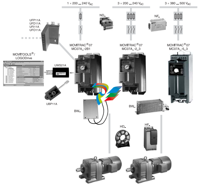
Overview of properties
Compact The unit has a very compact structure
• Integrated brake chopper
• Integrated EMC line filter:
– Class B: 1-phase connection
– Class A: 3-phase connection
– 230 V: 0.37 ... 7.5 kW
– 400/500 V: 0.55 ... 11 kW
• Braking resistor can be integrated (optional for sizes 0S, 0M, 0L)
• Book-shaped design with IP20 enclosure / NEMA1 (size 4: IP00, with touch guard
IP10)
Straightforward Startup and operation are very straightforward
• Automatic motor adaptation
• Integrated operating panel with menu structure
• Startup based on the "plug and play" principle
• Integrated setpoint potentiometer
• Easy parameter setting and diagnosis using MOVITOOLS® PC software
Right for the job The unit has the right function for every application
• Standard V/f control process or field-oriented VFC control mode as an option
• High overload capacity
– 125 % IN continuous duty (fan/pump operation)
– 150 % IN for maximum 60 seconds
– Maximum 180 % breakaway torque
• Integrated PI-controller
• Extended temperature range
– –10 °C ... +50 °C
– 230 V: 0.37 ... 2.2 kW
– 400/500 V: 0.55 ... 4.0 kW
– 0 °C ... +50 °C
– 230 V: 3.7 ... 30 kW
– 400/500 V: 5.5 ... 30 kW
• Integrated protection and monitoring functions
– Short circuit
– Ground fault
– Motor temperature sensor
System bus With the system bus (SBus) fitted as standard, you can network up to 64 MOVITRAC®
07 frequency inverters as slaves. A PC, a PLC or a MOVIDRIVE® can be the SBus master.
The MOVITRAC® 07 Communication manual describes the functions of the system bus.
Extended functions:
230 V units from 3.7 kW onwards and 500 V units from 5.5 kW onwards offer an extended range of functions including:
• Flying restart circuit
• Hoisting function
• Setpoint stop function
• Master frequency
• Standstill current function
• SCOPE oscilloscope program for MOVITOOLS®
LOGODrive units There is the LOGODrive series of units as well as the standard series. These differ from
the standard series in the following respects:
• The optional LOGODrive graphical programming interface is integrated in the
MOVITOOLS® software from version 2.6 onwards. You can add and link function
blocks into a sequential function chart graphically using LOGODrive.
• LOGODrive units also have the extended functions.
There is a separate manual for the LOGODrive graphical programming interface.
2.3 Functions / features
MOVITRAC® 07 frequency inverters are characterized by the following attributes:
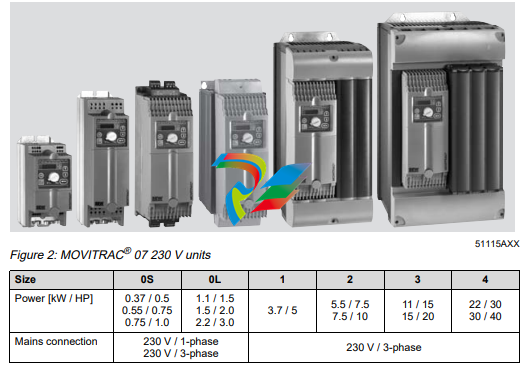
Unit properties • Wide voltage range:
– 230 V units 1-phase and 3-phase for the voltage range 200 ... 240 VAC, 50/60 Hz
– 400/500 V units for the voltage range 3 x 380 ... 500 VAC, 50/60 Hz
• Overload capacity: 150 % IN for maximum 60 s
125 % IN continuous power (fan/pump operation)
Maximum 180 % breakaway torque
• Rated operation (IN = 100 %) up to ambient temperature ϑ = 50 °C.
• 4-quadrant capability due to the integrated brake chopper.
• Compact unit mounting position for minimum switch cabinet space requirement and
optimum utilization of switch cabinet volume.
• Integrated EMC line filter to EN 55011 for compliance with limit value class:
– Class B: 1-phase connection
– Class A: 3-phase connection
– 230 V: 0.37 ... 7.5 kW
– 400/500 V: 0,55 ... 11 kW
• Inputs and outputs programmable
– 1 analog input
– 5 binary inputs
– 2 binary outputs, 1 of which is a relay output
• Integrated voltage supply and evaluation for TF (PTC temperature sensor) for temperature monitoring of the motor.
• Integrated operating panel for displaying setpoints and setting parameters
– 10 LEDs for displaying the selected symbols
– 5 operation buttons
– 1 setpoint potentiometer for specifying the speed
• Braking resistor can be integrated as an option in sizes 0S, 0M and 0L.
Control functions • VFC control mode or V/f control.
• Automatic brake control by the inverter.
• DC braking to decelerate the motor even in 1-quadrant mode.
• Slip compensation for high static speed accuracy.
• Motor pull-out protection by sliding current limitation in the field weakening range.
• Factory settings can be reactivated.
• Parameter lock to protect against parameter changes
• Protective features to protect against
– Overcurrent
– Ground fault
– Overload
– Overtemperature of the inverter
– Overtemperature of the motor
• Speed monitoring and monitoring of the motor and regenerative limit power.
• Fault memory with all relevant operating data at the moment of the fault.
• Standardized operation, parameter setting and identical unit connection technology
across all units in the MOVITRAC® 07 range.
Setpoint technology
• Motor potentiometer.
• External setpoint selections:
– 0 ... +10 V
– 0 ... 20 mA
– 4 ... 20 mA
• 6 fixed setpoints.
• Frequency input (in preparation).
Communication /
operation
• System bus for networking max. 64 MOVITRAC® 07 units.
• RS-485 interface for service purposes.
• Straightforward parameter setting and startup using integrated operating panel or
MOVITOOLS® PC software.
• LOGODrive graphical programming interface for writing programs.
• Parameter module for saving and transferring inverter data including the LOGODrive
program.
• Fieldbus interfaces for
– PROFIBUS
– DeviceNet
– INTERBUS
– CANopen
Extended functions:
230 V units from 3.7 kW onwards, 500 V units from 5.5 kW onwards and LOGODrive
units offer an expanded range of functions including:
• Standstill current function for:
– Rapid start
– Heating current for avoiding condensation at low temperatures
• Flying restart circuit for flying restart of the inverter.
• Hoisting capability with all approved motor options.
General technical data
The following technical data applies to all MOVITRAC® 07 frequency inverters, regardless of size
MOVITRAC® 07 All sizes
Interference immunity To EN 61800-3
Interference emission with
EMC-compliant installation
To limit value class
• B: 1-phase connection
• A: 3-phase connection
– 230 V: 0.37 ... 7.5 kW
– 400/500 V: 0.55 ... 11 kW
To EN 55011 and EN 55014; complies with EN 61800-3
Discharge current > 3.5 mA
Ambient temperature ϑamb
at fPWM = 4 kHz
230 V, 0.37 ... 2.2 kW
400/500 V, 0.55 ... 4.0 kW
• –10 °C ... +50 °C at 100 % IN
• –10 °C ... +40 °C at 125 % IN
230 V, 3.7 ... 30 kW
400/500 V, 5.5 ... 30 kW
• 0 °C – +50 °C at 100 % IN
• 0 °C ... +40 °C at 125 % IN
Power reduction 3.0 % IN per K to max. 60 °C
Climate class EN 60721-3-3, class 3K3
Storage temperature1
Transport temperature
1 If the unit is being stored for a long time, connect it to the mains voltage for at least 5 minutes every 2
years. Otherwise, the service life of the unit will be reduced.
–25 °C ... +75 °C
–25 °C ... +75 °C
Enclosure IP20
Size 4 power connections: IP00, IP10 with Plexiglas cover
mounted (supplied as standard)
Operating mode Continuous duty (EN 60149-1-1 and 1-3)
Altitude h ≤ 1000 m (3300 ft)
• IN reduction
– 1 % per 100 m (330 ft)
– From 1000 m to max. 4000 m (3300 ft to max. 13,200 ft)
• VN reduction
– 3 V per 100 m (330 ft)
– From 2000 m to max. 4000 m (6600 ft to max. 13,200 ft)
Over 200 m (6600 ft) only overvoltage class 2, external measures are required for overvoltage class 3. Overvoltage classes
to DIN VDE 0110-1.
Vibration-resistance To EN 50 178 / VDE 0160
Technical data of MOVITRAC® 07
-
 HIRSCHMANN MSM20-M2M2M2M2SY9HH9E Ethernet media modul
 -
 HIRSCHMANN SPIDER-PL-20-05T1999999TWVHHHH Industrial Ethernet Rail Switch
 -
 Hirschmann SPIDER-PL-20-07T1M2M299TWVHHHH Industrial ETHERNET Rail Switch
 -
.png) Hirschmann (Belden) RS20-1600M2M2SDAEHC09.1.00 DIN-rail managed industrial Fast Ethernet switch
Hirschmann (Belden) RS20-1600M2M2SDAEHC09.1.00 DIN-rail managed industrial Fast Ethernet switch -
 Hirschmann (Belden) RS30-1602O6O6TDAPHC09.1.00 DIN-rail managed industrial Ethernet switch
 -
 Hirschmann (Belden) RS30-2402O6T1SDAPHH09.0.13 DIN-rail industrial Ethernet switch
 -
Hirschmann (Belden) SPIDER-PL-20-04T1S29999TY9HHHH Ethernet DIN-rail switch
-
 HIRSCHMANN RS20-1600T1T1SDAUHX Switch
 -
 HIRSCHMANN BRS42-0012OOOO-SPCZ99HHSES industrial switch
 -
 Hirschmann RS20-0800S2S2TDHPHH09.0.14 Fast Ethernet DIN rail switch.
 -
 HIRSCHMANN MM20-Z6Z6M2M2SAHH Hybrid Fast Ethernet Media Module
 -
 HIRSCHMANN MM20-Z6Z6T1T1SAHH hot-swappable hybrid Fast Ethernet Media Module
 -
 HIRSCHMANN MM20-P9P9T1T1SAHH Hybrid Fast Ethernet Media Module
 -
 HIRSCHMANN MM20-M4T1T1T1SAHH Hybrid Fast Ethernet Media Module
 -
 HIRSCHMANN MM20-M4M4T1T1SAHH Hybrid Fast Ethernet Media Module
 -
 HIRSCHMANN MM20-M2M2M2M2SZHH Ethernet media module
 -
HIRSCHMANN MM20-M2M2M2M2SAHH Ethernet media module
-
 HIRSCHMANN MM20-T1T1T1T1EBH 4-port Fast Ethernet Copper Cable Media Module
 -
HIRSCHMANN MM20-T1T1T1T1SAHH 4-port Fast Ethernet Copper Cable Media Module
-
HIRSCHMANN MM20-T1T1T1T1SAHH 4-port Fast Ethernet Copper Cable Media Module
-
 HIRSCHMANN MM20-Z6Z6EBH Hot-swappable fast Ethernet media module
 -
 HIRSCHMANN MM20-Z6Z6SAHH Ethernet media module
 -
HIRSCHMANN MM20-Z6Z6Z6Z6EBH Industrial Media Module
-
 MSM40-T1T1T1TZ9HH9E99.9.99 HIRSCHMANN Switch
 -
 HIRSCHMANN MS20-0800SAAEHC / MS20-0800SAAEHC0 8-port modular Layer 2 management Ethernet switch
 -
 Hirschmann RSPM20-4T14T1SZ9HHS9 Switch RSPM20-4T14T1SZ9HHS9
 -
 HIRSCHMANN RS20-1600M2M2SDAEHH09.1. RS20/30/40 Managed Switch configurator
 -
HIRSCHMANN RS20-1600M2M2SDAEHX09.0.00 Ethernet switch
-
 HIRSCHMANN BELDEN SPIDER-PL-20-07T1M2M299TY9HHHH / SPIDERPL2007T1M2M299TY9HHHH
 -
HIRSCHMANN MM3-1FXS2/3TX1 Switching Board Module
-
 HIRSCHMANN RSPE30-24044O7T99-ECCP999HHSE2A08.1.00 Industrial-grade fanless management-type Ethernet switch
 -
 HIRSCHMANN RS30-1602OOZZSDAEHC09.1.00 DIN-rail-mounted managed Layer 2 Ethernet switch
 -
 HIRSCHMANN MACH104-20TX-F Managed 24-port Full Gigabit 19" Switch
 -
 HIRSCHMANN Switch RS20-0800M4M4SDAE
 -
Hirschmann RS30-1602O6O6SDAEHH09.1. Management-type Ethernet switch
-
 Hirschmann RS30-1602OOZZSDAEHC09.0.10 Open rack-style Ethernet switch
 -
 HIRSCHMANN RSPE30-24044O7T99-SCCV999HHSI2SXX.X.XX High-Availability Seamless Redundancy
 -
HIRSCHMANN RSPE30-24044O7T99-SCCZ999HHSE2A DIN-rail Ethernet switch
-
HIRSCHMANN MM2-4TX1-EEC switch
-
HIRSCHMANN MSM40-T1T1T1T1TZ9HH9E99.9.99 Module
-
 HIRSCHMANN RS20 Rail Switch RS20-0400S4T1SDAEHC07.1.01
 -
 HIRSCHMANN M4-FAST8-SFP Fast Ethernet media module
 -
 HIRSCHMANN RS20-0400M2T1SDAP Managed Fast-Ethernet-Switch
 -
 HIRSCHMANN BELDEN SPIDER II 8TX/1FX EEC Industrial Ethernet Rail Switch
 -
HIRSCHMANN MM3-2FXS2/2TX1
-
 HIRSCHMANN RS2-4TX/1FX EEC Industrial Ethernet Rail Switch
 -
 RS30-0802O6O6SDAEHC09.0.10 HIRSCHMANN Switch
 -
 HIRSCHMANN m4-8TP-RJ45 Ethernet Media Module
 -
 HIRSCHMANN MSP30-24040SCZ9URHHE3A switch
 -
 Hirschmann rack MS30-1602SAAPHC
 -
 HIRSCHMANN RS2-FX/FX Industrial Switch Module
 -
Rs1txfx - Hirschmann - Rs1-Tx/Fx Rail Switch
-
RS20-0800S2S2SDAEHC09.1.00 HIRSCHMANN Commutator
-
 Hirschmann EAGLE20 TX/TX Industrial Security Router
 -
 Hirschmann SPIDER-SL-20-04T1S29999SY9HHHH Industrial Switch
 -
 HIRSCHMANN MAR1040-4C4C4C4C9999SMMHRHHXX.X. Gigabit Ethernet Switch configurator
 -
 Hirschmann MAR1040 Industrial Switch
 -
 HIRSCHMANN BELDEN RS30-1602O6O6SDAE
 -
Hirschmann RS20-1600M2M2SDAUHC Ethernet DIN rail switch
-
 HIRSCHMANN OCTOPUS 24M industrial switch
 -
 HIRSCHMANN RS20-1600T1T1SDAE Management-type Ethernet switch
 -
 HIRSCHMANN RS20-1600T1T1SDAUHH industrial switch
 -
HIRSCHMANN RS20-0800M2M2SDAPHC09.0.04 switch
-
 Hirschmann MR 8-03 24V DC Industrial Modular Bridge/Router
 -
 HIRSCHMANN RS20-0400M2T1SDAPHC08.0.01 Managed Switch
 -
 MACH1130 Hirschmann Industrial Switch
 -
 HIRSCHMANN 943824-002 SPIDER 5TX Industrial Ethernet Switch
 -
 HIRSCHMANN RS30-0802O6O6SDAEHC09.1.00 Managed Industrial Switch
 -
 HIRSCHMANN RS20-0400M2M2TDAEHC04.0.01 Industrial Switch
 -
 HIRSCHMANN BRS20-0600Z6Z6-STCZ99HHSES Industrial Switch
 -
 HIRSCHMANN MACH104-20TX-FR-L3P Industrial Ethernet Switch
 -
 HIRSCHMANN RS40-0009CCCCEDBPHH06.0.01 Industrial Switch
 -
 HIRSCHMANN RS2-3TX/2FX EEC Industrial Ethernet Switch
 -
 Hirschmann MACH 1020/1030 Fast/Gigabit Rack Mount Switches
 -
HIRSCHMANN RS20-0800M2M2SDAPHC09.0.14 Industrial Switch
-
 HIRSCHMANN RS20-1600T1T1SDAEHC09.0.04 Industrial Switch
 -
 HIRSCHMANN RSB20-0800T1T1EAABHH Industrial Switch
 -
 HIRSCHMANN MACH4002-48+4G-L3E Industrial Backbone Switch
 -
 HIRSCHMANN RS20-0400S2T1SDAE Industrial Managed Switch
 -
HIRSCHMANN RS20-0800S2T1SDAUHC Industrial Switch
-
 HIRSCHMANN RS20-2400S4S4SDAEHC09.0.14 industrial switch
 -
 HIRSCHMANN OS20-001200T5T5T5- TBBZ999HHNE3S 08.1.00 industrial switch
 -
HIRSCHMANN OS20-001200T5T5T5- TBBZ999HHNE3S 08.1.00 industrial switch
-
 HIRSCHMANN RS40-0009CCCCSDAEHH09.0.14 switch
 -
 Hirschmann RS20-1600T1T1SDAUHC Management-type Ethernet Switch
 -
 Hirschmann M1-8SFP Switche
 -
Hirschmann Industrial Ethernet Ruggedized Switch MACH1000 Family
-
 Basler Electric, Solid State Protective Relay, BE1-60
 -
BASLER ELECTRIC SR4A-2B15B3A Static Voltage Regulator
-
.png) BASLER ELECTRIC EXCITER DIODE MONITOR EDM-200
BASLER ELECTRIC EXCITER DIODE MONITOR EDM-200 -
.png) BASLER ELECTRIC DECS125-15-B2C5 DIGITAL EXCITATION CONTROL SYSTEM V 2.0.9
BASLER ELECTRIC DECS125-15-B2C5 DIGITAL EXCITATION CONTROL SYSTEM V 2.0.9 -
 BASLER ELECTRIC BE1-851 OVERCURRENT PROTECTION RELAY MECHANISM
 -
 Basler Electric BE1-51A / BE151A
 -
 Basler Electric BE1-40Q Loss of Excitation Relay
 -
 Basler Electric BE1-87G Variable Percentage Differential Relay
 -
 Basler Electric BE1-11 Protection System I5A3M2P2N0EA00
 -
 BASLER ELECTRIC DECS-200-1C Digital Excitation Control System
 -
 Basler Electric / Kohler BE1-11g Generator Protection Relay G5A3M2J2N0E000
 -
BASLER ELECTRIC DECS125-15 DIGITAL EXCITATION CONTROL SYSTEM
-
 BASLER ELECTRIC BE1-951 OverCurrent Protecton System
 -
Basler Electric DECS-200-1L Digital Excitation Control System
-
 Basler Electric DGC-2020HD-5NS1DNSBA Digital Genset Controller -
 -
 BASLER ELECTRIC BE1-81T1EE1WA0N1F / BE181T1EE1WA0N1F
 -
 BASLER ELECTRIC BE1-25M1EA6PN5R1F / BE125M1EA6PN5R1F
 -
 BASLER ELECTRIC DECS-250-LN1SN1N DIGITAL EXCITATION CONTROL SYSTEM
 -
Basler Electric DECS-250-CN2CN 1N Digital Excitation Control System Unit
-
 BASLER ELECTRIC DECS-300-C0N0 DIGITAL EXCITATION CONTROL SYSTEM
 -
 BASLER ELECTRIC BE1-87T-A1E-A1J-D0S1F / BE187TA1EA1JD0S1F
 -
BASLER ELECTRIC BE1-11-G6D1M0J2P0E000 Protection System
-
 BASLER ELECTRIC BE1-GPS100-E4N1H1N GENERATOR PROTECTION SYSTEM
 -
 Jaquet Relay card (Auxiliary module) FTV 3090 377Z-03985
 -
 Jaquet Trip Chain Control card FTBU 3034 377Z-05030
 -
 Jaquet with input card -E04 FTFU 3024 -E04 377Z-05855
 -
 Jaquet with input card -E03 FTFU 3024- E03 377Z-03983
 -
 Jaquet FTFU 3024- E02 377Z-03982 with input card -E02
 -
 Jaquet FTFU 3024-E01 377Z-03981 with input card -E01
 -
 Hirschmann RS20-2400T1T1SDAE Industrial Managed Ethernet Switch
 -
 Hirschmann BELDEN EAGLE30-04022O6TT999SCCV9HSE3F
 -
 Hirschmann MM3-2FXS2/2TX MICE Media Module
 -
 Hirschmann RS20-1600M2M2SDAPHC08.0.05 Industrial Managed Switch
 -
 Hirschmann OZD Profi 12M G12-1300 PRO Fieldbus Repeater
 -
Hirschmann SPIDER 4TX/1FX-ST EEC Industrial Ethernet Switch
-
 Hirschmann MM2-2FXM3/2TX1 MICE Media Module
 -
 Hirschmann RS20-2400M2M2SDAPHC09.0.14 Industrial Switch
 -
 Hirschmann RS20-0400M2M2SDAEHC07.1.05 OpenRail Switch
 -
 Hirschmann OZD Profi 12M G12-EEC Fieldbus Repeater
 -
HIRSCHMANN MDA422-1/2-3.5c-23/46 sensor
-
Hirschmann RS30-2402T1T1SDAUHC Managed Industrial Switch


