
Vibro-Meter ® VM600 IOC4T input/output card
cards using the VM600 rack’s Raw bus or Open Collector (OC) bus.
For IOC4T card relay features, see Relay characteristics on page 4.
For further information on RLC16 or IRC4 relay cards, refer to the
corresponding data sheet.
Note: In a VM600 rack (ABE4x), the Open Collector (OC) bus and/or Raw bus can be used to connect up to
32 outputs from an MPC4/IOC4T card pair to RLC16 relay cards or IRC4 intelligent relay cards in the same rack,
if additional relays are required.
Analog (DC) outputs
Number of outputs : 4 per IOC4T card (one per MPC4 dynamic signal channel)
Signal range : Current output (4 to 20 mA) or voltage output (0 to 10 V),
individually selectable by a jumper on the IOC4T for each output.
Note: For current outputs, the analog output is actually driven in a
slightly wider 2 to 23 mA range, proportional to the input signal.
Accuracy : ≤±1.5%
Linearity error : ≤±0.5%
Admissible load on output : >100 kΩ for voltage output.
<325 Ω for current output.
Relay characteristics
Relay names : RL1 to RL4
Type : PE014005
Contact arrangement : 1 x NC or 1 x NO contact per relay (user configurable).
The selected contacts are available on J2.
Nominal rated voltage : 250 VAC
Nominal rated current : 5 AAC
Maximum breaking capacity
(without contact protection)
: 1250 VA
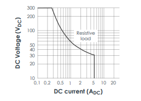
Maximum DC load breaking capacity curve
Operate / release / bounce time : Typically 8 / 8 / 6 ms
Dielectric strength test voltages
• Between open contacts : 1000 VAC
• Between contact and coil : 4000 VAC
Mechanical life : 15 x 106 operations
Electrical life : >105 operations
When used in a VM600 slimline rack (ABE056) with a DC power supply, the relay contacts on an IOC4T card
have a maximum switching voltage of 70 VDC / 33 VAC (RMS) (46.7 VAC (PEAK)
Environmental
Temperature
• Operating : −25 to 65°C (−13 to 149°F)
• Storage : −40 to 85°C (−40 to 185°F)
Humidity
• Operating : 0 to 90% non-condensing
• Storage : 0 to 95% non-condensing
Approvals
Conformity : CE marking, European Union (EU) declaration of conformity.
EAC marking, Eurasian Customs Union (EACU) certificate /
declaration of conformity.
Electromagnetic compatibility : EN 50081-2 and EN 50082-2.
IEC/EN 61000-6-2 and IEC/EN 61000-6-4.
TR CU 020/2011.
Electrical safety : IEC/EN 61010-1.
TR CU 004/2011.
Vibration : IEC 60255-21-1 (Class 2)
Insulation coordination for measuring
relays and protection equipment
: Separate circuits according to IEC 60255-5
for the “separate circuits” version of the IOC4T
Safety integrity level : SIL 1 according to IEC 61508
Environmental management : RoHS compliant
Russian federal agency for technical
regulation and metrology (Rosstandart)
: Pattern approval certificate CH.C.28.004.A N° 60224
Communications
MPC4 to IOC4T bus : Similar to industry pack (IP)
Configuration
MPC4/IOC4T card pair : Software configurable via an RS-232 or Ethernet connection, using
a computer running the VM600 MPSx software.
Hardware configurable using jumpers on the MPC4/IOC4T card
pair.
Note: Configuration via an Ethernet connection requires a CPUx card acting as a rack controller in the VM600
rack.
Status indicators (LEDs)
SLOT ERROR : Used to indicate indicates whether the IOC4T is installed in the
correct slot of the VM600 rack
Power supply to card (input)
Power source : VM600 rack power supply
Supply voltages : +5 VDC and ±12 VDC
Consumption from +5 VDC supply : 1.5 W
Consumption from ±12 VDC supply : 0.7 W, plus an additional 0.25 W per current output used
S
Connectors
J1 : 16-contact screw-terminal connector.
Inputs (analog signals) for dynamic measurement channels 1 to 4.
J2 : 16-contact screw-terminal connector.
Inputs (analog signals) for tachometer (speed) channels 1 to 2.
Outputs (contacts) for relays RL1 to RL4.
J3 : 16-contact screw-terminal connector.
Outputs (analog signals) for DC outputs 1 to 4.
Inputs (digital signals) for DSI control signals: AR, DB and TM.
Outputs (analog signals) for buffered “raw” sensor outputs for
dynamic measurement channels 1 to 4.
Physical
Height : 6U (262 mm, 10.3 in)
Width : 20 mm (0.8 in)
Depth : 125 mm (4.9 in)
Weight : 0.25 kg (0.55 lb) approx.
ORDERING INFORMATION
To order please specify
Type Designation Ordering number (PNR)
IOC4T Different versions of the input/output card (for the MPC4):
– Standard 200-560-000-1Hh
– Separate circuits 200-560-000-2Hh
Notes
Versions of the IOC4T card are available with a conformal coating (“varnish”) applied to the circuitry of the card for additional
environmental protection against chemicals, dust, moisture and temperature extremes.
In 2017, the MPC4 / IOC4T machinery protection card pairs were improved to (1) be RoHS compliant and (2) provide a reduced
buffered dynamic signal output impedance, which required a redesign of the underlying buffered “raw” dynamic signal output
circuitry. Accordingly, the different versions of the MPC4/IOC4T machinery protection card pairs in use are:
• Later versions of the MPC4 (PNRs 200-510-SSS-115, 200-510-SSS-214 and 200-510-SSS-313 or later) and
IOC4T (PNR 200-560-000-114 and 200-560-000-212 or later), which are RoHS compliant and have an output impedance of 50 Ω.
• Earlier versions of the IOC4T (PNRs 200-510-SSS-114, 200-510-SSS-213 and 200-510-SSS-312 or earlier) and
-
 Applied Materials (AMAT) 0190-04098 | 5.X Factory Interface I/O Distribution Board
 -
 Applied Materials (AMAT) 0190-03705 | MF Producer SE/E Interlock Module
 -
 Applied Materials (AMAT) 0190-02748 | Flex Scanner Transition Module
 -
 Applied Materials (AMAT) 0190-02362 | Mainframe Interlock 1 Relay Module
 -
 Applied Materials (AMAT) 0190-01227 | Intelligent Motor Control OMS Board
 -
 Applied Materials (AMAT) 0190-00318 | VME 486 Video Controller
 -
 Applied Materials (AMAT) 0130-14007 | Advanced RF Signal Assembly
 -
 Applied Materials (AMAT) 0130-14005 | RF Cable/Interface Assembly
 -
 Applied Materials (AMAT) 0130-01218 | High-Efficiency RF Interface Controller
 -
 Applied Materials (AMAT) 0110-77040 | Head Pneumatic Controller
 -
 Applied Materials (AMAT) 0110-00077 | Precision Control Module
 -
 AMAT 0101-57015 high-performance Next-Generation Deflection Amplifier Board
 -
 AMAT 0100-77040 critical Head Pneumatic Controller Board
 -
 AMAT 0100-76291 Data Buffer / Memory Expansion Interface
 -
 AMAT 0100-76290 Advanced I/O Interface Board
 -
 AMAT 0100-76269 Control Board / Interface Module
 -
 AMAT 0100-71462-01 high-performance Process Controller PCB
 -
 AMAT 0100-71171 Chamber Interlock Control PCB
 -
 AMAT 0100-71154 Semiconductor Circuit Board / Electronic Group Card
 -
 AMAT 0100-70034 PCB Assembly (PCBA) for Endpoint VGA I/O Interconnect.
 -
 AMAT 0100-38032 ESC (Electrostatic Chuck) Controller PCB
 -
 AMAT 0100-36035 DPS Source Match / Seriplex I/O Distribution PCB
 -
 AMAT 0100-35231 Seriplex I/O Distribution Module
 -
 AMAT 0100-35217 TC Amp Interlock PCB Module
 -
 AMAT 0100-35065 High-Precision Serial Isolator PCB
 -
 AMAT 0100-35054 Advanced Chamber Interface Module
 -
 AMAT 0100-20453 DeviceNet Digital I/O Interface Board
 -
 AMAT 0100-20100 High-Performance Semiconductor Component
 -
 AMAT 0100-20068 Precision CCD Image Control Board
 -
 AMAT 0100-20064 Advanced Semiconductor Control Module
 -
Applied Materials (AMAT) 0100-20018 Advanced Communication Interface Module
-
 Applied Materials (AMAT) 0100-20016 High-Performance Interface and Control Module
 -
 Applied Materials (AMAT) 0100-20003 Digital I/O (DI/DO) Interface Board
 -
 Applied Materials (AMAT) 0100-20001 System Electronics Interface (SEI) / PCB Assembly
 -
 Applied Materials (AMAT) 0100-11030 Chamber Hardware / Gas Distribution Component
 -
 Applied Materials (AMAT) 0100-11022 Semiconductor Board Card
 -
 Applied Materials (AMAT) 0100-11018 Advanced Interface Control Module
 -
 Applied Materials (AMAT) 0100-11001 Precision Analog Output Board
 -
 Applied Materials (AMAT) 0100-11000 High-Precision Analog Input Board
 -
 Applied Materials (AMAT) 0100-09237 Advanced Signal Interface Module
 -
 Applied Materials (AMAT) 0100-09204 Advanced Digital Interface Control Board
 -
 Applied Materials (AMAT) 0100-09172 High-Density Digital I/O Control Board
 -
 Applied Materials (AMAT) 0100-09137 High-Performance VME Control Module
 -
 Applied Materials (AMAT) 0100-09054 Precision Analog Input Board
 -
 Applied Materials (AMAT) 0100-09029 Turbo Interconnect Interface Module
 -
 AMAT 0100-03391 Precision Semiconductor Control
 -
 AMAT 0100-01984 | VME System Interface & Logic Controller Board
 -
 AMAT 0100-01363 | VME Intelligent System Control & I/O Board
 -
 AMAT 0100-01321 | VME DeviceNet Scanner / Interface Board
 -
AMAT 0100-00793 | VME Multi-Channel Interface & Logic Board
-
 AMAT 0100-00689 | VME PCB Power Module
 -
 AMAT 0100-00580 | VME Intelligent System Controller Board
 -
 AMAT 0100-00523 | VME Multi-Channel Analog-to-Digital (A/D) Board
 -
 AMAT 0100-00493 | VME Multi-Function System Controller Board
 -
 AMAT 0100-00398 | VME Interface System Control Board
 -
 AMAT 0100-00369 | VME 12-Channel High-Speed Stepper Motor Controller
 -
 AMAT 0100-00196 | VME System Mainframe CPU Controller Board
 -
 AMAT 0100-00169 | VME 12-Channel Stepper Motor Controller Board
 -
 AMAT 0100-00162 | VME Dual Channel Serial Communication Board
 -
 AMAT 0100-00137 | VME Stepper Motor Controller Interface Board
 -
 AMAT 0100-00075 | VME Digital Input/Output (DI/O) Interface Board
 -
 AMAT 0100-00007 VME Analog Input/Output Interface Board
 -
 AMAT 0100-00002 | VME Slave I/O Interface PCB
 -
 AMAT 0090-05596 High-Voltage DC Power Cable Assembly
 -
 AMAT 0090-01809 | High-Performance RF Power Cable Assembly
 -
 AMAT 0010-29958 | CCM HART 3 Mainframe Control Assembly
 -
 AMAT 0010-20003 System Controller Card Cage Assembly
 -
.png) AMAT 0010-11239 PVD High-Voltage Power Interface Assembly
AMAT 0010-11239 PVD High-Voltage Power Interface Assembly -
 AMAT 0010-09416 RF Matching Network Assembly
 -
 AMAT 0010-00019 Analog Power Supply Assembly
 -
 AMAT AS00009-02 (31-000-00940) | Precision Semiconductor Component
 -
 AMAT 0010-00028 Power Supply Module
 -
 AMAT 0330-1586A Serial Communication PCB
 -
 AMAT 0190-09690 Seriplex SENSORbus SPX-MUXADIO-001
 -
 AMAT 0190-04397 DeviceNet I/O Interface Board
 -
 AMAT 0190-02506 DeviceNet I/O Interface Card
 -
 AMAT 0090-00475 Seriplex 210 MUXADIO
 -
 AMAT 410-0198-1 Multi-Output Switching Power Supply
 -
 AMAT 0100-20458 high-reliability Configurable Interlock Personality Board
 -
 AMAT VAS104350-0415 Gasline Heater Control Unit
 -
 AMAT VME6U1V2 VMEbus Backplane Interface Module
 -
AMAT 0920-01070 high-performance RF Power Generator
-
 AMAT 0090-76133A VME Single Board Computer (SBC)
 -
 AMAT 0190-24115 DeviceNet I/O Interface Card
 -
 AMAT 0190-37607 Backplane / Base Board Assembly
 -
 AMAT 0190-32372 Analog Input/Output (I/O) Board
 -
 AMAT 0190-09956 Loadlock Interface PCB Base Assembly
 -
 AMAT 0190-07908 four-channel DeviceNet Interface Card
 -
 AMAT 0190-07905 (UPS) control board
 -
 AMAT 0190-07502 Precision Controller / Interface Board
 -
 AMAT 0190-03680 I/O Backplane
 -
 AMAT 0190-02200 Water Leak Detection Control Board
 -
 AMAT 0100-76124 Digital I/O Board Assembly
 -
 AMAT 0100-35563 Leak Detector Configuration PCB
 -
 AMAT 0100-35250 Chamber Interface DPS Centura PCB
 -
 AMAT 0100-35124 Seriplex I/O Distribution Board
 -
 AMAT 0100-35058 Loadlock Interlocks PCB
 -
 AMAT 0100-20213 RF Match Detector PCB
 -
 AMAT 0100-20063 Interface PCB Assembly
 -
 AMAT 0100-09225 TC AMP/INTERLOCK PCB
 -
 AMAT 0100-09153 Gas Panel Interface PCB
 -
 AMAT 0100-09127 Loader Interconnect Board
 -
 AMAT 0100-09009 Buffer I/O PCB Card
 -
 AMAT 0100-02813 Signal Conditioning Board
 -
 AMAT 0100-01911 AC Gas Heater Control Board
 -
 AMAT 0100-01708 Pedestal Integration PCB
 -
 AMAT 0100-00658 300mm RTP Controller Distribution PCB
 -
 AMAT 0100-00582 Gas Panel Controller Backplane
 -
 AMAT 0100-00049 Analog Signal Conditioner
 -
 AMAT 0100-00008 Control Interface Module
 -
 AMAT 0090-03402 DC Power Supply / Power Module
 -
 AMAT 0090-01248 DC Power Supply / Power Module
 -
 AMAT 0090-76109 RF Matching / Capacitor Assembly
 -
 AMAT 0101-57106 Substrate Voltage Board
 -
 AMAT 0101-57014 Deflection-Amplifier PCB
 -
 AMAT 0101-57012 AKT Column Control PCB (COL-C 50-10)
 -
 AMAT AKT 0241-58482 PCB
 -
 AMAT 0241-58255 REV05 PCB
 -
 AMAT 0161-57042 AKT framework
 -
 AMAT 0101-57196 electronic control board
 -
 AMAT 0101-57178 Digital Input / Interface PCB
 -
 AMAT 0101-57162 electronic control board
 -
 AMAT 0101-57127 P-DRV (Power Driver Board)
 -
 AMAT 0101-57126 D-AMP 50-06 (Digital/Analog Amplifier)
 -
 AMAT 0101-57125 AKT COL-C Communication Board
 -
AMAT 0101-57120 D-OUT 50-32 (Digital Output Board)
-
 AMAT 0101-57112 D-IN 50-32 (Digital Input Board)
 -
 AMAT 0101-57102 electronic control board


