
Woodward High Output Digital Valve Positioner (DVP)DVP5000/DVP10000/DVP12000
at the time of installation is required to assure satisfactory operation of the product.
Verify details concerning installation mounting requirements: Ground straps, lock washers, etc.
2.5 Mechanical Installation Requirements
This section provides the general information for mounting location selection, installation, and wiring of
the Digital Valve Positioner (DVP).
2.5.1. Unpacking the Shipping Carton
• Before unpacking the control, refer to the inside front cover of this manual and to the Regulatory
Compliance page for warnings and cautions. Be careful when unpacking the control. Check for signs
of damage such as bent or dented panels, scratches, and loose or broken parts. If any damage is
found immediately notify the shipper.
• The DVP is shipped from the factory in an antistatic foam-lined carton. This carton should always be
used for transport of the DVP when it is not installed. Read the Electrostatic Discharge Awareness
page before handling the DVP.
• Check for and remove all manuals, connectors, mounting screws, and other items before discarding
the shipping box.
2.5.2. General Installation and Mounting Considerations
When selecting a location for mounting the DVP consider the following:
• Protect the unit from direct exposure to water or a condensation-prone environment.
• The DVP is designed for installation in a low vibration environment. If installed in vibration levels
above normal control room levels, the DVP should be vibration isolated from engine and generator
vibrations above 50 Hz. See Grounding Requirements above.
• Install the DVP5000/DVP10000 in an area where the operating temperatures will not exceed -40°C
to +70°C (-40°F to +158°F).
• Install the DVP12000 in an area where the operating ambient temperatures will not exceed -40°C to
+70°C (-40°F to +158°F) for 25A operation and -40°C to +55°C (-40°F to +131°F) for 28A operation.
The Woodward Actuator/Valve determines the DVP12000 operating current.
• The DVP is designed for rear panel mounting to a metal surface and adequate clearance around the
air intake and exhaust openings.
• The DVP can be mounted in any orientation with proper clearance provided to allow air flow. For
maximum thermal performance, the DVP must be mounted in a vertical orientation.
• Shield the unit from radiant heat sources.
• Allow adequate space around the unit for servicing and cable routing.
• Do not install near high-voltage or high-current devices.
• Install the DVP in an area where there is a protection from outside contamination.
• Installation Clearance: 6 inches on the top and 6 inches on the bottom in addition to proper airflow
ventilation in the cabinet for 100 CFM (or 2.8 cubic meters/minute) of unobstructed airflow per unit.
No clearance is required on the sides for cooling.
• Verify that cable lengths do not exceed lengths specified in the electrical I/O section of this manual.
• Refer to Technical Specifications for packaging heat load information
2.5.3. Wire Preparation and Connector Screw Torque Drive Recommendation
Woodward recommends that the following wire preparation and terminal block screw torque specifications
for all DVP input/output terminal blocks.
Note: Stranded wire is recommended.
Table 2-1. Wire Hookup Guideline
Specification
I/O Terminal Block
Power Terminal Blocks
Wire Gauge
20 – 16 AWG
(0.5 – 1.0 mm²)
8 to 18 AWG 1
6 to 18 AWG 2
(0.75 to 6 mm²)
Wire Strip
Length
0.25 – 0.300 Inches
(6.4–7.6 mm)
0.45 – 0.55 Inches
(11.4–14.0 mm)
Recommended
Torque drive on
the Terminal
Block Connector
2.5 – 3.5 lb-in
(0.3 – 0.4 Nm)
Table Notes
1- 8 to 18AWG is for DVP5000 and DVP10000
2 – 6 to 18 AWG is for DVP12000
2.5.4. Connector Kits
10 – 12 lb-in
(1.1 – 1.4 Nm)
The DVP is shipped with mating connectors for all input and output connectors. However, in some
applications where an extra set of connectors is needed, Woodward carries a connector kit as shown on
Table 2-2.
2.5.5. DVP 5000 and DVP10000 Configuration Options
The DVP10000 is the same as the DVP5000 with the addition of a boost module to increase power
temporarily to meet high performance actuator requirements. The DVP10000 package is slightly wider
than the DVP5000 to accommodate the boost module.
The DVP12000 is the same as the DVP10000 with a temperature derating option for higher output current
availability and the ability to operate with spring return actuators.
Additional Options:
• EXTERNAL SHUTDOWN feature is optionally certified to a SIL 3 level. The certified versions are
indicated on the front panel by DVP5000-S, DVP10000-S and DVP12000-S labels.
• Optional Ethernet Communication capability.
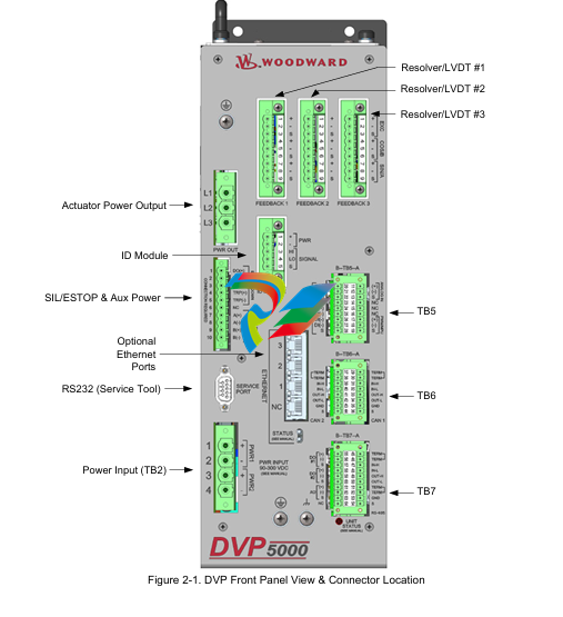
2.5.6. Terminal Locations
All terminals and connectors are located on the front panel of the chassis. Figures 2-2 and 2-3 show the
front panel and outline views. For EMC compliance, mount the DVP with low impedance bond to Earth
ground.
2.6 Fan Assembly Replacement
The fan assembly in the DVP is designed for field replacement if necessary. If one or both fans fail, an
alarm is generated.
The fans are a ball bearing type with a nominal airflow of 51.97 CFM (1.47m3/min) each.
A degraded fan can occasionally be identified by audible noise sounding like a low rumbling or roughness
from the bearings. In this case, it is advisable to replace the fan assembly at the earliest opportunity.
-
 Hirschmann M1-8SFP Switche
 -
 Hirschmann Industrial Ethernet Ruggedized Switch MACH1000 Family
 -
 Basler Electric, Solid State Protective Relay, BE1-60
 -
BASLER ELECTRIC SR4A-2B15B3A Static Voltage Regulator
-
.png) BASLER ELECTRIC EXCITER DIODE MONITOR EDM-200
BASLER ELECTRIC EXCITER DIODE MONITOR EDM-200 -
.png) BASLER ELECTRIC DECS125-15-B2C5 DIGITAL EXCITATION CONTROL SYSTEM V 2.0.9
BASLER ELECTRIC DECS125-15-B2C5 DIGITAL EXCITATION CONTROL SYSTEM V 2.0.9 -
 BASLER ELECTRIC BE1-851 OVERCURRENT PROTECTION RELAY MECHANISM
 -
 Basler Electric BE1-51A / BE151A
 -
 Basler Electric BE1-40Q Loss of Excitation Relay
 -
 Basler Electric BE1-87G Variable Percentage Differential Relay
 -
 Basler Electric BE1-11 Protection System I5A3M2P2N0EA00
 -
 BASLER ELECTRIC DECS-200-1C Digital Excitation Control System
 -
 Basler Electric / Kohler BE1-11g Generator Protection Relay G5A3M2J2N0E000
 -
BASLER ELECTRIC DECS125-15 DIGITAL EXCITATION CONTROL SYSTEM
-
 BASLER ELECTRIC BE1-951 OverCurrent Protecton System
 -
Basler Electric DECS-200-1L Digital Excitation Control System
-
 Basler Electric DGC-2020HD-5NS1DNSBA Digital Genset Controller -
 -
 BASLER ELECTRIC BE1-81T1EE1WA0N1F / BE181T1EE1WA0N1F
 -
 BASLER ELECTRIC BE1-25M1EA6PN5R1F / BE125M1EA6PN5R1F
 -
 BASLER ELECTRIC DECS-250-LN1SN1N DIGITAL EXCITATION CONTROL SYSTEM
 -
Basler Electric DECS-250-CN2CN 1N Digital Excitation Control System Unit
-
 BASLER ELECTRIC DECS-300-C0N0 DIGITAL EXCITATION CONTROL SYSTEM
 -
 BASLER ELECTRIC BE1-87T-A1E-A1J-D0S1F / BE187TA1EA1JD0S1F
 -
BASLER ELECTRIC BE1-11-G6D1M0J2P0E000 Protection System
-
 BASLER ELECTRIC BE1-GPS100-E4N1H1N GENERATOR PROTECTION SYSTEM
 -
 Jaquet Relay card (Auxiliary module) FTV 3090 377Z-03985
 -
 Jaquet Trip Chain Control card FTBU 3034 377Z-05030
 -
 Jaquet with input card -E04 FTFU 3024 -E04 377Z-05855
 -
 Jaquet with input card -E03 FTFU 3024- E03 377Z-03983
 -
 Jaquet FTFU 3024- E02 377Z-03982 with input card -E02
 -
 Jaquet FTFU 3024-E01 377Z-03981 with input card -E01
 -
 Hirschmann RS20-2400T1T1SDAE Industrial Managed Ethernet Switch
 -
 Hirschmann BELDEN EAGLE30-04022O6TT999SCCV9HSE3F
 -
 Hirschmann MM3-2FXS2/2TX MICE Media Module
 -
 Hirschmann RS20-1600M2M2SDAPHC08.0.05 Industrial Managed Switch
 -
 Hirschmann OZD Profi 12M G12-1300 PRO Fieldbus Repeater
 -
 Hirschmann SPIDER 4TX/1FX-ST EEC Industrial Ethernet Switch
 -
 Hirschmann MM2-2FXM3/2TX1 MICE Media Module
 -
 Hirschmann RS20-2400M2M2SDAPHC09.0.14 Industrial Switch
 -
 Hirschmann RS20-0400M2M2SDAEHC07.1.05 OpenRail Switch
 -
 Hirschmann OZD Profi 12M G12-EEC Fieldbus Repeater
 -
 HIRSCHMANN MDA422-1/2-3.5c-23/46 sensor
 -
Hirschmann RS30-2402T1T1SDAUHC Managed Industrial Switch
-
 Hirschmann OZD GENIUS G12 Industrial Switche
 -
 Hirschmann OZD 485 G12-1300 PRO Fieldbus Repeater
 -
 Hirschmann MM2-2FXM2 MICE Media Module
 -
 Hirschmann RS20-1600S2T1SDAUHC Managed Industrial Switch
 -
 Hirschmann MS20-0800SAAEHH04.2.04 MICE Switch
 -
 Hirschmann SPIDER 4TX/1FX EEC Unmanaged Industrial Switch
 -
 HIRSCHMANN MS4128-L3P EEC Managed Industrial Ethernet Switch
 -
 HIRSCHMANN RS20-0400M2T1SDAPHC08.0.01 Managed Switch
 -
 ETEL EA-S0M-400-40/80A-0000-00 AccurET Modular Power Supply
 -
 ETEL EA-B0I-0-0-0000-00 Backplane Interface Board
 -
 ETEL EA-P2M-400-15/40A-0100-00 Position Controller
 -
ETEL EA-P2M-400-15/40A-0000-00 Position Controller
-
 ETEL EA-P2M-400-10/20A-0100-01 Position Controller
 -
 ETEL EA-P2M-400-10/20A-0000-01 Position Controller
 -
 ETEL EA-P2M-400-5/10A-0100-01 Position Controller
 -
 ETEL EA-P2M-048-2.5/5A-0000-01 Modular Position Controller
 -
 ETEL EA-S0M-300-40/80A-0000-00 Power Supply Module
 -
 ETEL EA-P2M-300-07/15A-0100-01 Position Controller
 -
 ETEL EA-P2M-300-07/15A-0000-01: Modular Position Controller
 -
 ETEL EA-P2M-300-4/7.5A-0100-01 Overview
 -
 Basler Electric MOC2. Motor Operated Potentiometer
 -
 Basler Electric BE1-11 RTD Module, Resistance Temperature Detector
 -
 Basler Electric RDP-110C, Remote Display Panel
 -
 Basler Electric VRM-2020. Voltage Regulation Module
 -
 Basler Electric IDP-1500. Interactive Display Panel
 -
 Basler Electric AEM-2020. Analog Expansion Module
 -
 Basler Electric IDP-2020. Interactive Display Panel
 -
 Basler Electric CEM-2020. Contact Expansion Module
 -
 Basler Electric CEM-125. Contact Expansion Module
 -
 Basler Electric BE2000E, Digital Voltage Regulator
 -
 Basler Electric SMC-150. Synchronous Motor Controller
 -
 Basler Electric AVC125-10. Voltage Regulator
 -
 Basler Electric BE1-25. Sync-Check Relay
 -
 Basler Electric DGC-2020ES, Digital Genset Controller
 -
 ETEL EA-P2M-400-5/10A-0000-01 Position Controller
 -
 Basler Electric BE1-64F, Ground Fault Relay
 -
 Basler Electric BE1-79M, Multi Shot Reclosing Relay
 -
 Basler Electric BE1-81O/U, Digital Frequency Relay
 -
 Basler Electric BE1-87B, High Impedance Bus Differential Relay
 -
 Basler Electric BE1-79A, Reclosing Relay
 -
 Basler Electric BE1-27. BE1-59. BE1-27/59. Voltage Relay
 -
 Basler Electric SMC-250. Synchronous Motor Controller
 -
 Basler Electric SGC-250N, Synchronous Generator Controller
 -
 Basler Electric SGC-250. Synchronous Generator Controller
 -
 Basler Electric BE1-50/51 Plug and Play and Retrofit Relays
 -
 Basler Electric DECS-2100. Digital Excitation Control System
 -
 Basler Electric DECS-250E, Digital Excitation Control System
 -
 Basler Electric BE1-700V, Voltage Only Digital Protective Relay
 -
 Basler Electric DECS-250. Digital Excitation Control System
 -
 Basler Electric DECS-450. Digital Excitation Control System
 -
 Basler Electric DECS-150. Digital Excitation Control System
 -
 Basler Electric ES-49. Temperature Relay
 -
 Basler Electric ES-81O/U, ES-81O,ES-81U Overfrequency Relay
 -
Basler Electric ES-74V, DC Voltage Sensing Relay
-
Basler Electric ES-27/59. Under/Overvoltage Relay
-
 Basler Electric ES-27. Undervoltage Relay
 -
 Basler Electric ES-25. Sync-Check Relay
 -
 Basler Electric ES-47, ES-47N Phase Sequence Relay
 -
Basler Electric ES-37.ES-37/51 Undercurrent Relay
-
 Basler Electric ES-32. Reverse Power Relay
 -
Basler Electric ES-59. Overvoltage Relay
-
 Basler Electric ES-55. Power Factor Relay
 -
 Basler Electric DGC-2020HD, Digital Genset Controller
 -
 Basler Electric BE1-FLEX, Protection, Automation, and Control System
 -
 Schneider GUTOR OC0935 Power Factor Sampling Board
 -
 Schneider GUTOR OC0922 Analog Signal Isolation Board
 -
 Schneider GUTOR OC0908 Battery Voltage Detection Board
 -
Schneider GUTOR OC0947 Temperature / IGBT Sampling Board
-
 Schneider GUTOR OP2601 Communication Expansion Board
 -
 Schneider Electric GUTOR OP2312 bypass control board
 -
 Schneider Electric GUTOR OP2130 Cooling Fan Monitoring & Control Board
 -
 Schneider Electric GUTOR OP2010 Battery Test Board / Battery Management Diagnostic Card
 -
Schneider Electric GUTOR OP2552 Three-phase Power Connection Board Assembly
-
 Schneider Electric GUTOR OP1922A Parallel Control Board / Load-Sharing Synchronization Module
 -
 Schneider Electric GUTOR OP6290B Inverter Feedback Acquisition Board / Signal Scaling Module
 -
Schneider GUTOR OP6280 Basic Signal Board
-
Schneider Electric GUTOR OP2456 / OP2456B Main control board
-
 Schneider Electric GUTOR OP2452 Power Plug-in Panel
 -
 Schneider Electric GUTOR OP2450 Parallel Communication Board
 -
Schneider Electric GUTOR OP2406 Interface Fuse Monitoring Board
-
 Schneider Electric GUTOR OC0919 High-Power Semiconductor Module
 -
 Schneider Electric GUTOR OP6281A System Logic Interface Board
 -
 Schneider Electric GUTOR OP6285A Power Signal Acquisition Board
 -
 Schneider Electric GUTOR OP2438 Fan Monitor & Drive Protection Board
 -
Schneider Electric GUTOR OP2446 Main Control CPU Board


