
Hirschmann MM2-2FXM2 MICE Media Module
Hirschmann MM2-2FXM2 MICE Media Module
The Hirschmann MM2-2FXM2 (Belden Part Number: 943 718-101) is a hot-swappable Ethernet media expansion module designed specifically for the Hirschmann MICE (MS20/MS30) modular industrial switch series.
Product Introduction / Overview
In highly dynamic industrial settings, networking demands are constantly evolving. Rather than replacing complete switch units when fiber demands increase, modular switches use hot-swappable expansion modules to scale smoothly.
The MM2-2FXM2 media module provides an immediate interface upgrade for MICE MS20 and MS30 switches. It adds two Multi-Mode 100Base-FX fiber optic ports with SC connectors directly to the main switch backplane. This expansion makes it simple to integrate a standard copper switch into a dual-fiber ring or star topology, maintaining high-speed uplinks up to 5 km away without needing extra panel space or separate DIN-rail converters.
Technical Table
| Feature / Parameter | Specification Details |
| Model Code | MM2-2FXM2 |
| Belden Order Code | 943 718-101 |
| Compatible Mainframes | Hirschmann MICE Switch Series (MS20 / MS30) |
| Port Count | 2 Ports |
| Port Type | 100BASE-FX (100 Mbps Fast Ethernet over Fiber) |
| Connector Interface | SC Duplex Sockets |
| Fiber Medium Compatibility | Multi-mode glass fiber ($50/125 mutext{m}$ or $62.5/125 mutext{m}$) |
| Transmission Distance | up to 5,000 m (using $50/125 mutext{m}$ fiber); up to 4,000 m (using $62.5/125 mutext{m}$ fiber) |
| Optical Transmitter Wavelength | 1300 nm |
| Power Consumption | Maximum 3.0 W |
| Interface Diagnostics | Link status and Activity LEDs per port; Module Power LED |
| Dimensions (W x H x D) | $38text{ mm} times 110text{ mm} times 79text{ mm}$ |
| Weight | Approximately 170 g |
Product Features / Core Advantages
Hot-Swappable Performance: Designed for zero-downtime maintenance. Slide the module in or out of an active MICE switch chassis without powering down the network or disrupting adjacent traffic.
Resilient SC Port Connections: Double SC fiber connections provide high mechanical retention, protecting against accidental cable disconnections on high-vibration factory floors.
Complete Software Integration: Once inserted, the host MS20/MS30 switch instantly auto-detects the MM2-2FXM2 module, assigning administrative controls to the new fiber ports in the web management GUI.
Low Power Footprint: Drawing a maximum of only 3.0 Watts from the chassis backplane, it keeps thermal loads inside dense cabinets to a minimum.
Related Models of the Same Series
The MICE media module family offers alternative options to match various copper, fiber, and distance needs:
MM2-2FXS2 (943 719-101): Features 2 x Single-Mode 100Base-FX SC ports for long-range links up to 30 km.
MM2-4TX1 (943 715-101): Features 4 x standard 10/100Base-TX RJ45 copper ports.
MM2-2FLM4 (943 720-101): Features 2 x legacy 10Base-FL multi-mode ST fiber ports.
MM3-4FSDP (943 839-001): Features gigabit capability with 4 x SFP fiber transceivers (for MS30 switches).
Environmental Tolerance Conditions
Operating Temperature Range: $0^circtext{C}$ to $+60^circtext{C}$ ($32^circtext{F}$ to $140^circtext{F}$)
Storage/Transport Temperature: $-40^circtext{C}$ to $+70^circtext{C}$
Relative Humidity: 10% to 95% (completely non-condensing)
Shock & Vibration: Certified to pass IEC 60068-2-27 (shock) and IEC 60068-2-6 (vibration) standards.
Approvals: cUL508 (safety), CE, FCC, and ATEX Zone 2 hazardous location certifications.
Installation Method
[MICE Switch Backplane]
^
| <-- Slide module along the guidelines
[MM2-2FXM2]
| <-- Tighten top/bottom mounting screws
Alignment: Align the side guide rails of the MM2-2FXM2 module with the empty expansion slot lines on your MICE MS20 or MS30 switch chassis.
Insertion: Slide the module firmly backward into the slot until the multi-pin backplane connector is fully engaged with the switch mainboard.
Securing: Tighten the two knurled retaining screws located at the top and bottom of the module housing to prevent loose connections or vibration issues.
Cabling: Remove the protective black dust covers and connect the multi-mode SC fiber cables (align Tx to Rx and Rx to Tx).
Operating Instructions
1. Configuration on Host Switch
The host switch dynamically registers the module upon insertion:
Open the host switch web browser GUI using the IP address of the parent MS20/MS30 switch.
Navigate to Port Configuration. Verify that the expansion ports are recognized as 100Base-FX fiber lines.
Set port parameters (such as link state alerts, VLAN assignments, or ring redundancy options) matching your network plan.
2. Visual Diagnosis (Front LEDs)
P LED (Power): Should be solid green, indicating the backplane is successfully supplying power to the module.
L/D LEDs (Port 1 & 2):
Solid Green: Healthy optical connection.
Flashing Green: Active data packet transmission.
Off: No active link detected.
Fault Diagnosis
"P" (Power) LED is Off:
Cause: The module is not fully seated in the chassis slot, or the parent switch has suffered a backplane issue.
Remedy: Loosen the mounting screws, pull the module out, inspect the rear pins for physical damage, and slide it back in firmly. Tighten screws securely.
"L/D" (Link) LED is Off after Fiber Connection:
Cause: Swapped Tx/Rx fibers, dirty fiber end-faces, or the link segment exceeds 5 kilometers.
Remedy: Cross-check your fiber lines to ensure the local Tx port connects to the remote Rx port. Use an optical cleaning pen to remove contaminants from the SC connectors.
Intermittent Signal Drops / Frame Errors:
Cause: Physical fiber bend exceeds limits, or dust has settled inside the optical transceivers.
Remedy: Ensure all fiber routing bends stay above the minimum 1-inch radius. Avoid keeping optical ports uncapped when cables are disconnected.
Storage Conditions
Keep the media module in its original static-shielding box inside a clean, dry room.
Storage Temperature Limit: $-40^circtext{C}$ to $+70^circtext{C}$.
Dust Prevention: Leave the protective plastic SC socket caps inserted until the moment you connect the actual patch cables. Dust contamination is the leading cause of optical power loss in industrial fiber environments.
| User name | Member Level | Quantity | Specification | Purchase Date |
|---|



-
 SELSEL-T401L Ultra-High-Speed Line Relay
 -
 SEL SEL-T400L Time-Domain Line Protection
 -
 SEL SEL-2664S Stator Ground Protection Relay
 -
 SEL SEL-787-2/-3/-4 Transformer Protection Relay
 -
 SEL SEL-787 Transformer Protection Relay
 -
 SEL SEL-751 Feeder Protection Relay
 -
 SEL SEL-700G Generator Protection Relay
 -
 SEL-487E Transformer Protection Relay
 -
 SEL-400G Advanced Generator Protection System
 -
 SEL SEL-387E Current Differential and Voltage Relay
 -
 SEL SEL-387A Current Differential and Overcurrent Relay
 -
 SEL SEL-387 Current Differential and Overcurrent Relay
 -
 SEL SEL-300G Generator Relay
 -
 SEL SEL-700BT Motor Bus Transfer Relay
 -
 CTI 2500 Series® Slice Ethernet Remote I/O System
 -
 CTI 2500 Series® Compact Programmable Automation Control System
 -
 CTI 2500 Series® Classic Programmable Automation Control System
 -
 CTI 2500 Series® Bases
 -
 SHINKAWA VM-25 Condition Monitoring System UPDATED
 -
 SHINKAWA VM-5 SERIES OPTIONS
 -
 ABB SACO 64D4 Annunciator unit
 -
 ABB SPAU 140 C Synchro-check relay
 -
 EATON Instructions for the FP-5000
 -
 HONEYWELL TDC 3000X Advanced Process Manager
 -
 HONEYWELL ENHANCED MICRO TDC 3000
 -
 VIBRO-METER VM600Mk2/ VM600 RPS6U rack power supplies
 -
 VIBRO-METER VM600Mk2/ VM600 ABE056 slimline rack
 -
 VIBRO-METER VM600Mk2 RLC16Mk2 relay modules
 -
 VIBRO-METER VM600Mk2 MPC4Mk2 + IOC4Mk2 machinery protection and condition monitoring modules
 -
 VIBRO-METER VM600Mk2 CPUMMk2 + IOCNMk2 rack controller and communications interface module
 -
 VIBRO-METER VM600Mk2 CPUMMk2 + IOCNMk2 rack controller and communications interface module
 -
 ADLINK PCI/PCIe-7300A, cPCI-7300 32-CH 80 MB/s High-Speed Digital I/O Cards
 -
 ADLINK cPCI-7248/7249R 48-CH DIO & Timer/Counter Cards
 -
 ADLINK PCI-7230/7233/7234. LPCI/LPCIe/cPCI-7230 32-CH Isolated DIO Cards
 -
 ADLINK cPCI-6965 Series Value 6U CompactPCI® Intel® Core™2 Duo
 -
 ADLINK cPCI-6910 Series 6U CompactPCI® Dual-Core Intel® Xeon® Processor LV / ULV Universal Blade
 -
 ADLINK CPCI-6670 6U CompactPCI Low Power Pentium® III SBC
 -
 ADLINK cPCI-6625/6 Series 6U CompactPCI® PlusIO blade with Intel® Core™ i7/i3 Processor
 -
 ADLINK 3U CompactPCI CPU Modules
 -
 ADLINK CM-435 Extreme Rugged™ PC/104 Single Board Computer
 -
 ADLINK PCI-8254/8258 DSP-based 4/8-axis Advanced Motion Controllers
 -
 ADLINK NuPRO-E43 PICMG® 1.3 Full-Size LGA1151 with 6th/7th Generation Intel® Core™ i7/i5/i3
 -
 ADLINK DLAP-211-JNX/DLAP-211-JT2/ DLAP-211-Nano
 -
 Hirschmann RS30-1602O6O6SDAE compact OpenRail managed Ethernet switches
 -
Hirschmann RS30-0802O6O6SDAE Ethernet switch
-
 Hirschmann RS20-1600T1T1SDAE Management-type Ethernet switch
 -
 Hirschmann OCTOPUS 24M Limited Availability/Passive
 -
 Hirschmann MSP30-24040SCZ9MRHHE3A
 -
 Hirschmann MAR1040-4C4C4C4C9999SMMHRHHXX.X. Gigabit Ethernet Switch configurator
 -
 Hirschmann Industrial Ethernet Rail Switch SPIDER II, SPIDER II Giga, SPIDER II PoE
 -
 Hirschmann Industrial Ethernet Firewall EAGLE One
 -
 Hirschmann Industrial Security Router EAGLE20/30
 -
 Hirschmann Description and operating instructions RS2-xTX/xFX EEC
 -
 Basler Electric DECS-200 Digital Excitation Control System
 -
 Basler Electric GENERATOR PROTECTION SYSTEM BE1-GPS100
 -
 Jaquet FT3000 Speed measurement system
 -
 Hirschmann Industrial Ethernet Ruggedized Switch MACH1000 Family
 -
 Basler Electric BESTCOMSPlus®
 -
 ETEL AccurET MODULAR 300 EA-P2M-300-xxxxxA controller
 -
 Basler Electric ES Series Protection Relays
 -
 ABB Multifunction Protection and Switchbay Control Unit REF542plus
 -
 EMERSON AMS 2140 Machinery Health Analyzer
 -
 Hirschmann Industrial Ethernet Rail Switch RS20 Basic Family
 -
 GE Grid Solutions P40U Px40 USB Adaptor
 -
 ABB ontinuous Gas Analyzers AO2000 Series AO2040CU Ex Central Unit in Category 2G
 -
 ABB Advance Optima AO2000 Series Continuous gas analyzers Models AO2020. AO2040
 -
 Advance Optima Module Uras 14
 -
 SAACKE control optimization
 -
 SAACKE se@vis efficiency monitor
 -
 SAACKE se@vis pro
 -
 SAACKE se@vis eco
 -
 SAACKE se@vis compact
 -
 HIRSCHMANN Industrial ETHERNET Switch MICE MS20/MS30
 -
 HIRSCHMANN MICE Media modules
 -
 Kongsberg GL-10 Level Switch
 -
 B&R ACOPOSinverter P74 frequency converter
 -
 Beckhoff CX2020 | Basic CPU module (service phase)
 -
 Beckhoff CX1010 | Basic CPU module (service phase)
 -
 Beckhoff CX5120 | Embedded PC with Intel Atom® E3815
 -
 Beckhoff CP69xx-xxxx-0010 | Economy built-in Control Panel with DVI/USB Extended interface
 -
 Beckhoff CP29xx-0000 | Multi-touch built-in Control Panel with DVI/USB Extended interface
 -
 SAACKE Monoblock Rotary Cup Burner SKVJ-M
 -
 ABB Plantguard Fault Tolerant Technology Architecture and Software
 -
 OMRON H8PR-8/H8PR-8P H8PR-16/H8PR-16P H8PR-24/H8PR-24P Rotary Positioner
 -
 ABB PFSA107-Z42 DTU Stressometer Digital Transmission Unit
 -
 Nidec Mentor MP
 -
 IBA ibaNet-E
 -
 IBA FO Connection to Reflective Memory
 -
 IBA FO Connection to Siemens Systems
 -
 IBA Interface Cards For Fiber Optic Connections
 -
 IBA Field and Drive Buses
 -
 IBA ibaPADU-S Modular System
 -
 IBA ibaMAQS
 -
 STUCKE SYMAP®ARC
 -
 STUCKE SYMAP®R
 -
 STUCKE SYMAP®Compact
 -
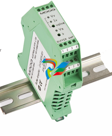 MOOG G123-825-001 BUFFER AMPLIFIER
 -
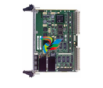 Motorola MVME5100 Series VME Processor Modules
 -
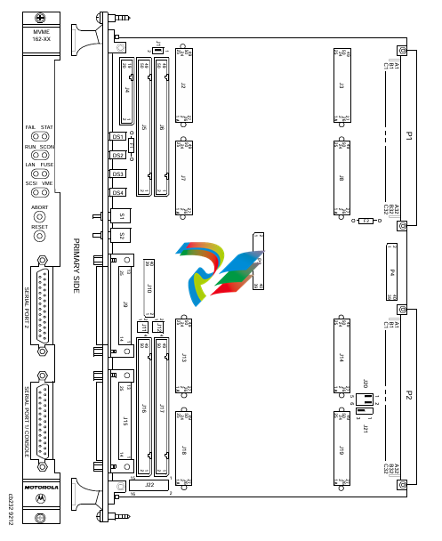 Motorola MVME162 Embedded Controller
 -
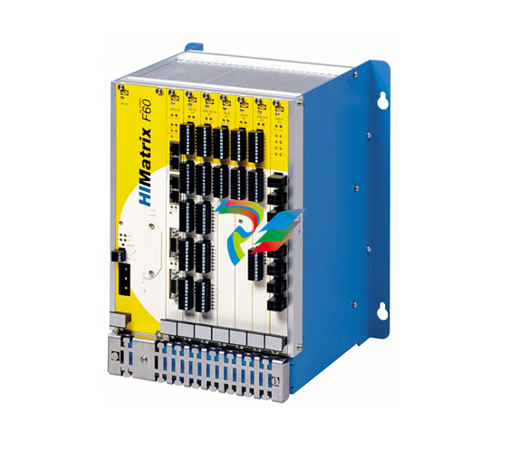 HIMatrix Safety-Related Controller System Manual for the Modular Systems
 -
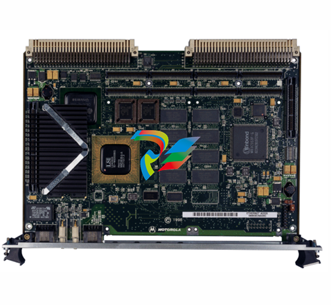 Motorola MVME2400 Series VME Processor Module
 -
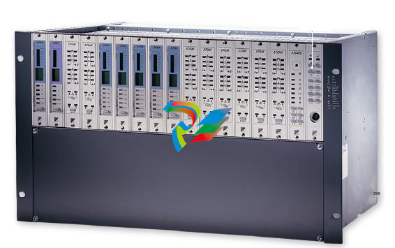 Sieger System 57
 -
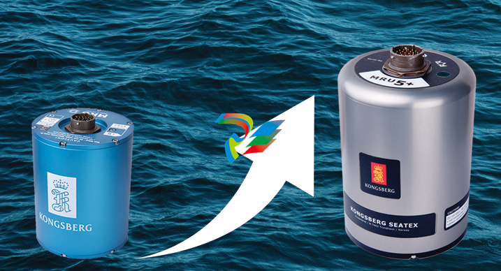 KONGSBERG MRU product line continuation
 -
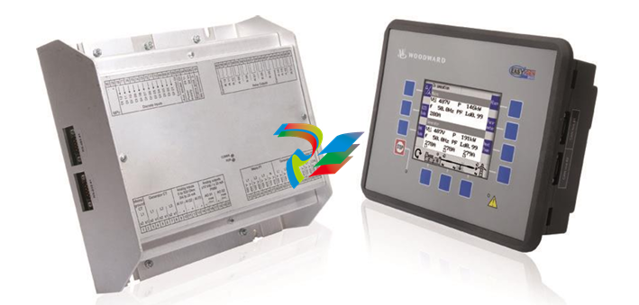 Woodward easYgen-3100/3200 Genset Control for Multiple Unit Operation
 -
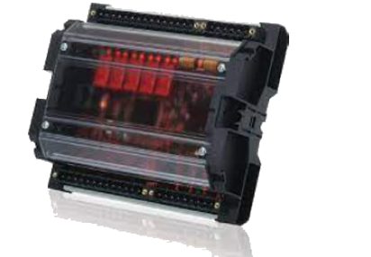 Woodward MFR 300 Multifunction Relay / Measuring
 -
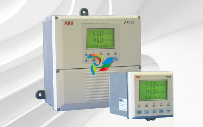 ABB AX410, AX411, AX413, AX416, AX418, AX450, AX455 and AX456 Single and dual input analyzers for low level conductivity
 -
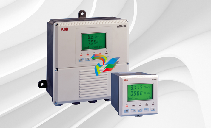 ABB AX410, AX411, AX416, AX450 and AX455 Single and dual input analyzers
 -
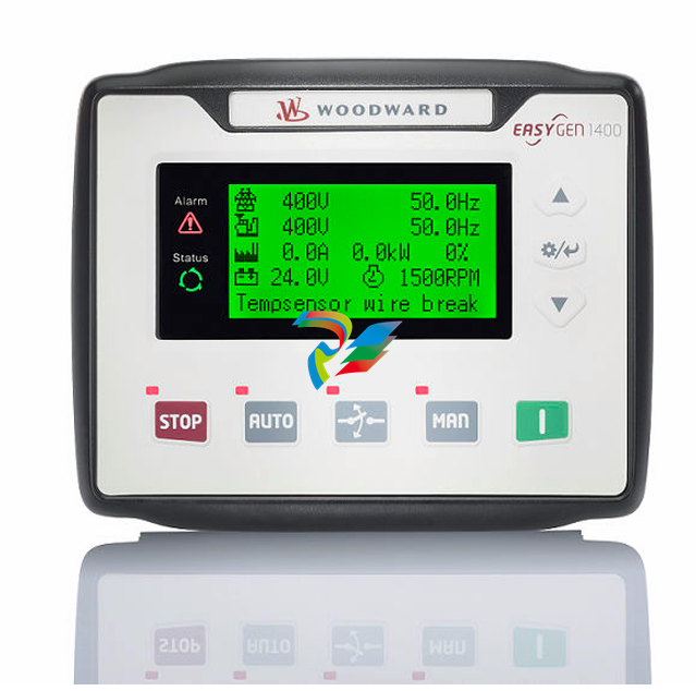 Woodward easYgen-1400 Technical Manual Genset Control
 -
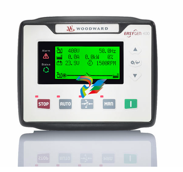 Woodward easYgen-400 Operation Manual Genset Control
 -
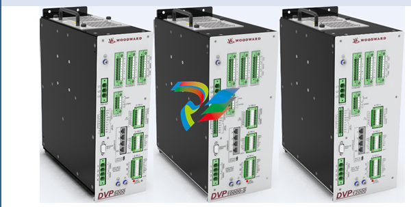 Woodward High Output Digital Valve Positioner (DVP)DVP5000/DVP10000/DVP12000
 -
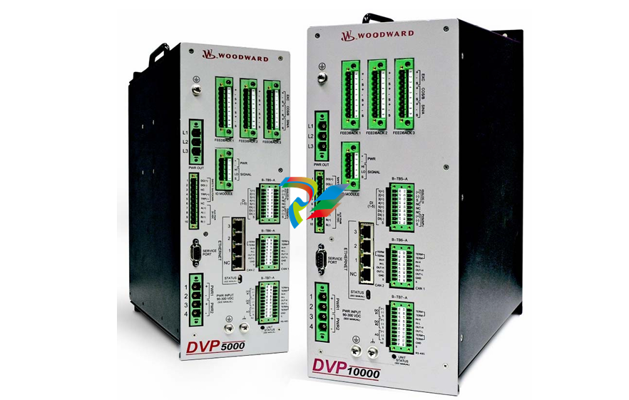 Woodward High Output Digital Valve Positioner DVP5000 and DVP10000
 -
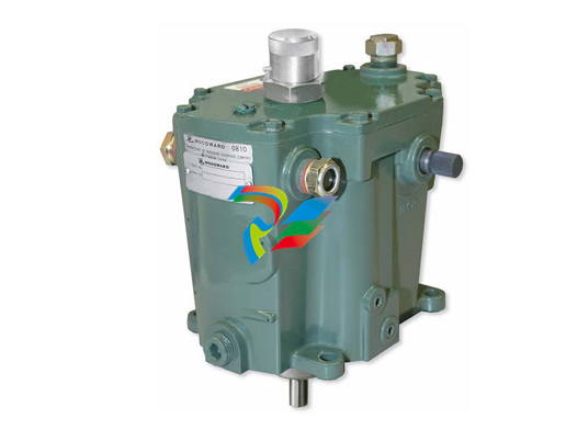 Woodward TG611-13/-17 Overspeed Test Device Conversion Kit
 -
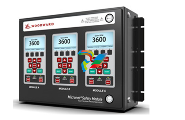 Woodward MicroNet Safety Module (MSM)
 -
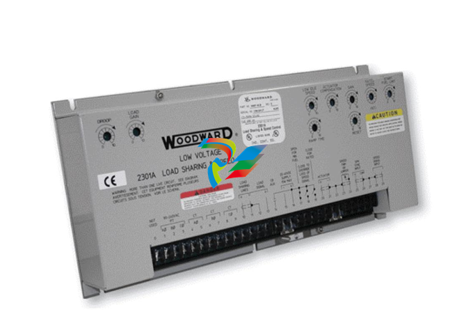 Woodward 2301A Electronic Load Sharing and Speed Control 9905/9907 Series
 -
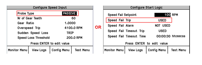 Woodward-Service Bulletin 01671
 -
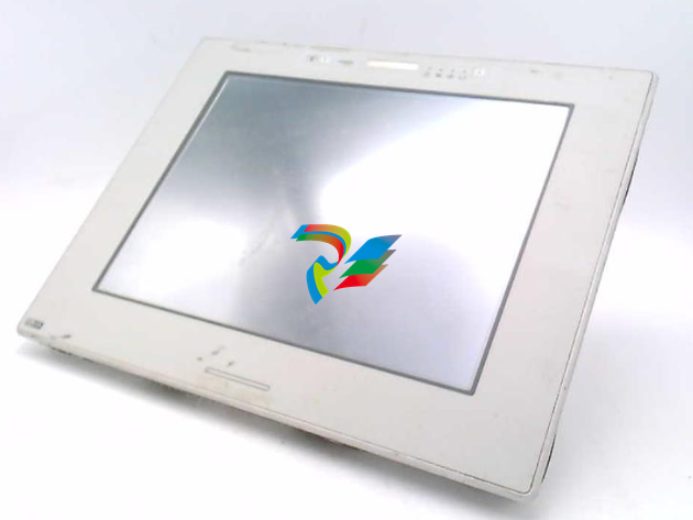 UniOP eTOP40B 12.1” TFT color display
 -
 UniOP eTOP40 TFT Color display
 -
 UniOP eTOP33B 10.4” TFT color display
 -
 UniOP eTOP33C eTOP33-0050 Resistive touchscreen
 -
UniOP eTOP30. eTOP32 eTOP32-0050 Human-machine interface equipment
-
 UniOP eTOP20B and eTOP21B eTOP20B-0050
 -
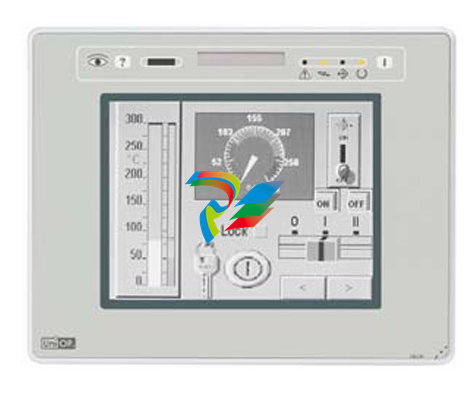 UniOP eTOP12 eTOP12-0050 Advanced human-machine interface equipment
 -
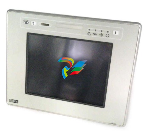 UniOP eTOP11 eTOP11-0050 HMI
 -
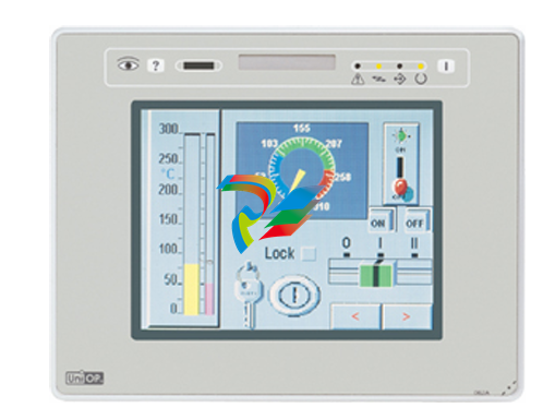 UniOP eTOP06C HMI
 -
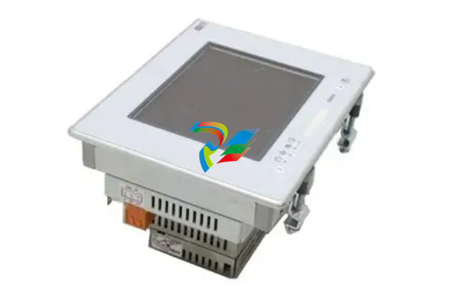 UniOP eTOP06 HMI
 -
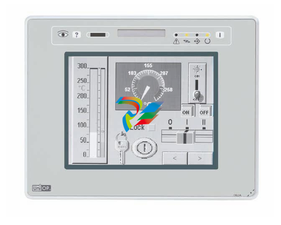 UniOP eTOP05EB eTOP05EB-DF45 HMI
 -
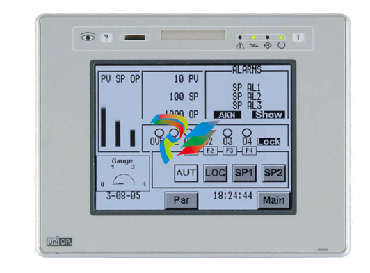 UniOP eTOP05. eTOP05P Human-machine interface equipment
 -
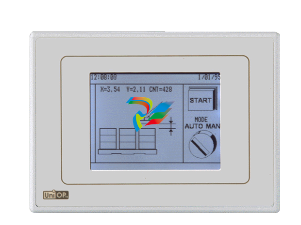 UniOP eTOP03 eTOP03-0046


