
ABB V18345
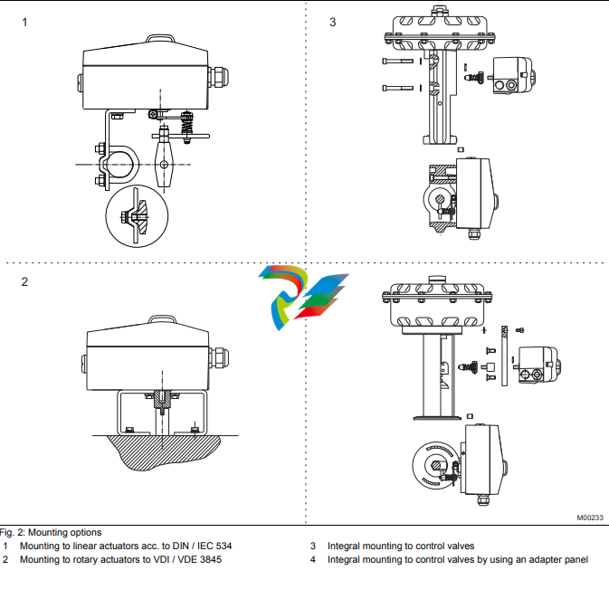
3.1.4 Diagnosis parameters Pos: 7.13 /Technische Daten / Datenblatt/Aktorik/Stellungsregler/Allgemein/Betrieb/Diagnoseparameter @ 10mod_1176214500906_3101.doc @ 77406 The diagnosis parameters of the TZIDC program inform the operator about the operating conditions of the valve. From this information the operator can derive which maintenance works are required, and when. Additionally, limit values can be defined for these parameters. When they are exceeded, an alarm is reported. The following values are e.g. determined: - Number of movements performed by the valve - Total travel The diagnosis parameters and limit values can be called up, set, and reset via HART communication, using the configuration program. Pos: 7.14 /Überschriften/1.1/2-spaltig/Bedienpanel @ 10mod_1176214143953_3101.doc @ 77229 3.2 Operator panel Pos: 7.15 /Technische Daten / Datenblatt/Aktorik/Stellungsregler/Allgemein/Betrieb/Bedienpanel TZIDC-1x0 @ 10mod_1176214815500_3101.doc @ 77427 The TZIDC positioner’s operator panel with four pushbuttons allows for - operational monitoring - manual control - configuration - fully automatic commissioning The operator panel is protected by a cover which avoids unauthorized access to the operating elements. Pos: 7.16 /======= Spaltenumbruch ======== @ 0mod_1132937966324_3101.doc @ 3831 Pos: 7.17 /Überschriften/1.1.1/2-spaltig/Ein-Tasten-Inbetriebnahme @ 10mod_1176214193156_3101.doc @ 77250 3.2.1 Single-button commissioning Pos: 7.18 /Technische Daten / Datenblatt/Aktorik/Stellungsregler/TZIDC / TZIDC-200/Betrieb/Ein-Tasten-Inbetriebnahme @ 10mod_1176214842843_3101.doc @ 77448 Commissioning the TZIDC positioner is especially easy. The standard Autoadjust function for automatic adaptation of the device parameters can be started by simply pressing a single front panel button, and without knowing parameterization details. Depending on the selected actuator type (linear or rotary), the displayed zero position is automatically adapted: - for linear actuators counter-clockwise (CTCLOCKW) - for rotary actuators clockwise (CLOCKW). Besides this standard function, a customized “Autoadjust” function is available. The function is launched either via the operator’s panel or HART communication. Pos: 7.19 /Überschriften/1.1.1/2-spaltig/Anzeigen @ 10mod_1176214259859_3101.doc @ 77271 3.2.2 Display Pos: 7.20 /Technische Daten / Datenblatt/Aktorik/Stellungsregler/TZIDC / TZIDC-200/Betrieb/Anzeigen @ 10mod_1176214873937_3101.doc @ 77469 The information indicated by the 2-line LC display is permanently updated and adapted during operation, to inform the operator in an optimal way. During control operation (control with or without adaptation) the following TZIDC data can be called up by pressing the pushbuttons briefly: - Up button: Current setpoint (mA) - Down button: Temperature in device - Up + Down buttons: Current control deviation
4.1 DTM Pos: 9.4 /Technische Daten / Datenblatt/Aktorik/Stellungsregler/TZIDC / TZIDC-200/Kommunikation/DTM @ 10mod_1176215507046_3101.doc @ 77595 The DTM (Device Type Manager) for TZIDC is based on the FDT/DTM technology (FDT 1.2) and can be integrated in a process control system or loaded in a PC with the DSV401 (SMART VISION) program. This allows you to work with the same user interface in the commissioning phase, during operation, and for service tasks for monitoring the device, setting parameters, and uploading data. Communication is based on the HART protocol. It occurs via a local interface connection (LKS) or in frequency-modulated mode using an FSK-modem connected at any chosen point of the 20 mA signal line. Communication has no effect on operation. Newly set parameters are saved in the non-volatile memory directly upon the download into the device, and become active immediately. Pos: 9.5 /Überschriften/1.1/2-spaltig/LKS-Adapter (RS-232 Schnittstellenwandler) @ 10mod_1176215338250_3101.doc @ 77532 4.2 LKS adapter (RS-232 interface converter) Pos: 9.6 /Technische Daten / Datenblatt/Aktorik/Stellungsregler/TZIDC / TZIDC-200/Kommunikation/LKS-Adapter (RS-232 Schnittstellenwandler) @ 10mod_1176215612828_3101.doc @ 77616 You can easily connect your TZIDC positioner to a PC, e.g., in the workshop or in the commissioning phase, by using the positioner’s LKS adapter (LKS = local communication interface). An RS-232 interface converter adapts the signals on the serial PC port to the level of the positioner’s LKS. Pos: 9.7 /Überschriften/1.1/2-spaltig/FSK-Modem @ 10mod_1176215390421_3101.doc @ 77553 4.3 FSK Modem Pos: 9.8 /Technische Daten / Datenblatt/Aktorik/Stellungsregler/TZIDC / TZIDC-200/Kommunikation/FSK-Modem @ 10mod_1176215656328_3101.doc @ 77637 The FSK modem establishes a digital frequency-modulated communication (Frequency Shift Keying) with the TZIDC positioner. Tapping is possible at any chosen point of the 20 mA signal line. We recommend that you use an electrically isolated FSK modem. It is bus-compatible when used with isolating amplifiers. Even connecting explosion-protected field devices is possible, on condition that the FSK modem is run outside the hazardous a
5 Technical data Pos: 11.2 /==== Wechsel ein- auf zweispaltig ==== @ 0mod_1130421847171_3101.doc @ 3828 Wechsel ein-auf zweispaltig Pos: 11.3 /Überschriften/1.1/2-spaltig/Eingang @ 0mod_1139395051468_3101.doc @ 3221 5.1 Input Pos: 11.4 /Technische Daten / Datenblatt/Aktorik/Stellungsregler/TZIDC / TZIDC-200/Technische Daten/Eingang / Stellsignal (Zweileitertechnik) @ 10mod_1176272560140_3101.doc @ 77936 Output signal (two-wire technology) Nominal range 4 ... 20 mA Split range configuration between 20 ... 100 % of the nominal range Max. 25 mA Min. 3.6 mA Starting at 3,8 mA Load voltage at 20 mA 9,7 V Impedance at 20 mA 485 Ω Digital input Control voltage 0 ... 5 V DC logical switching state "0" 11 ... 30 V DC logical switching state "1" Current max. 4 mA Pos: 11.5 /Überschriften/1.1/2-spaltig/Ausgang @ 10mod_1176215873937_3101.doc @ 77658 5.2 Output Pos: 11.6 /Technische Daten / Datenblatt/Aktorik/Stellungsregler/TZIDC / TZIDC-200/Technische Daten/Ausgang / Druckluftausgang @ 10mod_1176272620812_3101.doc @ 77957 Compressed air output Range 0 ... 6 bar (0 ... 90 psi) Air capacity 5.0 kg/h = 3.9 Nm³/h = 2.3 sfcm at 1.4 bar (20 psi) supply pressure 13 kg/h = 10 Nm³/h = 6,0 sfcm at 6 bar (90 psi) supply pressure Output function For single or double-acting actuators, air is vented from actuator or actuator is blocked in case of (electrical) power failure Shut-off values End position 0 % = 0 ... 45 % End position 100 % = 55 ... 100 % Digital output (control circuit to DIN 19234/NAMUR) Supply voltage 5 ... 11 V DC Current > 0.35 mA … < 1.2 mA Switching state logical "0" Current > 2.1 mA Switching state logical "1" Effective direction (configurable) normally logical "0" or logical "1" Pos: 11.7 /Überschriften/1.1/2-spaltig/Stellweg @ 10mod_1176215894234_3101.doc @ 77679 5.3 Travel Pos: 11.8 /Technische Daten / Datenblatt/Aktorik/Stellungsregler/TZIDC / TZIDC-200/Technische Daten/Stellweg / Drehwinkel @ 10mod_1176272774203_3101.doc @ 77978 Rotation angle Used range 25 ... 120 (rotary actuators, optional 270°) 25 ... 60 ° (linear actuators) Travel limit Min. and max. limits, freely configurable between 0 ... 100 % of total travel (min. range > 20 %) Travel time prolongation Range of 0 ... 200 seconds, separately for each direction Dead band time limit Range 0 ... 200 seconds (monitoring parameter for control until the deviation reaches the tolerance band) Pos: 11.9 /======= Spaltenumbruch ======== @ 0mod_1132937966324_3101.doc @ 3831 Pos: 11.10 /Überschriften/1.1/2-spaltig/Luftversorgung @ 10mod_1176215914875_3101.doc @ 77700 5.4 Air supply Pos: 11.11 /Technische Daten / Datenblatt/Aktorik/Stellungsregler/Allgemein/Technische Daten/Luftversorgung TZIDC-1x0 @ 10mod_1176272806906_3101.doc @ 77999 Instrument air free of oil, water and dust acc. to DIN / ISO 8573-1 pollution and oil content according to Class 3 (purity: max. particle size: 5 µm, max. particle density: 5 mg / m3; oil content: max. concentration: 1 mg / m3; pressure dew point: 10 K below operating temperature Supply pressure 1.4 ... 6 bar (20 ... 90 psi) Note: Do not exceed the max. operating pressure of the actuator! Air consumption < 0,03 kg/h / 0,015 scfm (independent of supply pressure) Pos: 11.12 /Überschriften/1.1/2-spaltig/Übertragungsdaten und Einflussgrößen @ 10mod_1176215939812_3101.doc @ 77721 5.5 Transmission data and influences Pos: 11.13 /Technische Daten / Datenblatt/Aktorik/Stellungsregler/TZIDC / TZIDC-200/Technische Daten/Übertragungsdaten und Einflussgrößen @ 10mod_1176272844734_3101.doc @ 78020 Output Y1 Increasing Increasing output signal 0 ... 100 % Increasing pressure at output Decreasing Increasing output signal 0 ... 100 % Decreasing pressure at output Action (positioning signal) Increasing Signal 4 ... 20 mA = actuator position 0 ... 100 % Decreasing Signal 20 ... 4 mA = actuator position 0 ... 100 % Characteristic curve (travel = f {signal}) Linear, equal percentage 1:25 or 1:50 or 25:1 or 50:1 and freely configurable with 20 reference points. Characteristic deviation < 0,5 % Tolerance band 0.3 ... 10 %, adjustable Dead band 0,1 ... 10 %, adjustable Resolution (A/D conversion) > 4000 steps Sample rate 20 ms Influence of ambient temperature < 0.5 % per 10 K Influence of vibration < ± 1 % to 10 g and 80 Hz Seismic requirements Meets requirements of DIN / IEC 68-3-3 Class III for strong and strongest earthquakes. Influence of mounting orientation Not measurable. Meets the requirements of the following directives - EMC Directive 89 / 336 / EWG as of May 1989 - EC Directive for CE conformity marking Communication - HART Protocol 5.1 - Local connector for LKS (local communication interface) adapter - HART communication via 20 mA signal line with (optional) FSK modem




.png)


.png)


.png)


